Sign In
Upload
Manuals
Brands
HP Manuals
Server
ProLiant DL360 Generation 4
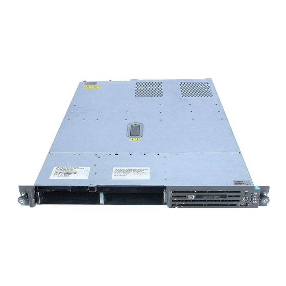
HP ProLiant DL360 Generation 4 Manuals
Manuals and User Guides for HP ProLiant DL360 Generation 4. We have
2
HP ProLiant DL360 Generation 4 manuals available for free PDF download: Reference And Troubleshooting Manual, Maintenance And Service Manual
HP ProLiant DL360 Generation 4 Reference And Troubleshooting Manual (246 pages)
WHP Wireless Server User Manual
Brand:
HP
| Category:
Server
| Size: 4.47 MB
Table of Contents
Table of Contents
3
In this Section Front Panel Components
7
Front Panel Leds and Buttons
8
Rear Panel Components
10
Rear Panel Leds and Buttons
11
System Board Components
12
System Maintenance Switch
13
NMI Switch
14
System Board Leds
14
System Leds and Internal Health LED Combinations
16
Internal USB Connector
17
SCSI Ids and SATA Device Numbers
18
Hot-Plug SCSI Hard Drive Leds
19
Hot-Plug SCSI Hard Drive LED Combinations
20
Optional Battery-Backed Write Cache Enabler Leds
21
Battery-Backed Write Cache Enabler LED Statuses
21
Fan Module Locations
22
Processor Zone Fan Module LED
23
Server Component Identification
7
Front Panel Components
7
Server Operations
25
In this Section Powering up the Server
25
Powering down the Server
25
Powering up the Server
25
Extending the Server from the Rack
26
Removing the Access Panel
27
Installing the Access Panel
28
Removing PCI Riser Board Assembly
28
Installing PCI Riser Board Assembly
29
Server Setup
31
In this Section Optional Installation Services
31
Optional Installation Services
31
Rack Planning Resources
32
Optimum Environment
33
Space and Airflow Requirements
33
Temperature Requirements
34
Power Requirements
35
Electrical Grounding Requirements
36
Rack Warnings
36
Identifying the Server Shipping Carton Contents
37
Installing Hardware Options
37
Installing the Server into the Rack
38
Powering up and Configuring the Server
39
Installing the Operating System
40
Registering the Server
41
Hardware Options Installation
43
In this Section Introduction
43
Introduction
43
Processor Option
43
Memory Options
46
DIMM Installation Guidelines
47
Online Spare Memory Configuration
47
Installing Dimms
48
Hard Drive Options
49
Removing a Hard Drive Blank
49
SCSI Hard Drive Guidelines
49
Installing a SCSI or SATA Hard Drive
50
Optical Device Option
51
Battery-Backed Write Cache Enabler Option
52
Redundant Hot-Plug AC Power Supply Option
54
Expansion Board Options
57
PCI Expansion Slot Definitions
57
Expansion Board
57
Installing an Expansion Board
58
Installing a PCI Express Riser Board
59
Server Cabling
63
Cabling Overview
63
Server Cable Routing
63
SATA Cable Routing
64
Server Software and Configuration Utilities
65
In this Section Configuration Tools
65
ROM-Based Setup Utility
67
Array Configuration Utility
70
Option ROM Configuration for Arrays
70
HP Proliant Essentials RDP
71
Re-Entering the Server Serial Number and Product ID
71
Management Tools
72
Automatic Server Recovery
72
Rompaq Utility
73
System Online ROM Flash Component Utility
73
Integrated Lights-Out Technology
74
Erase Utility
75
HP Systems Insight Manager
76
Management Agents
76
Redundant ROM Support
76
USB Support and Functionality
78
Diagnostic Tools
79
Survey Utility
79
Server Software and Configuration Utilities
65
Configuration Tools
65
Smartstart Software
65
Configuration Tools
79
List of Tools
79
Array Diagnostic Utility
80
HP Insight Diagnostics
80
Integrated Management Log
80
Drivers
81
Keeping the System Current
81
Care Pack
82
Change Control and Proactive Notification
82
Operating System Version Support
82
Proliant Support Packs
82
Resource Paqs
82
Battery Replacement
83
Important Safety Information
85
Server Diagnostic Steps
85
Troubleshooting
85
Preparing the Server for Diagnosis
89
Symptom Information
90
Diagnostic Steps
91
Hardware Problems
105
Procedures for All Proliant Servers
105
List of Problems/CD-Rom and DVD Drive Problems
112
Internal System Problems
112
List of Problems
112
CD-ROM and DVD Drive Problems
112
DAT Drive Problems
113
Data Read from the Drive Is Inconsistent, or Drive Cannot Read Data
113
Drive Is Not Detected
113
Diskette Drive Problems
114
DLT Drive Problems
116
Fan Problems
118
Hard Drive Problems
119
Memory Problems
121
Action
121
PPM Problems
124
Processor Problems
124
List of Problems/Video Problems
126
List of Problems
126
External Device Problems
126
Video Problems
126
Screen Is Blank for more than 60 Seconds after You Power up the Server
126
Monitor Does Not Function Properly with Energy Saver Features
127
Video Colors Are Wrong
127
Audio Problems
128
Mouse and Keyboard Problems
128
Slow-Moving Horizontal Lines Are Displayed
128
Printer Problems
128
Video Problems
129
Diagnostic Adapter Problems
129
Modem Problems
129
List of Problems
129
Network Controller Problems
133
Software Problems
135
General Remote Rom Flash Problems Are Occurring
142
Remote ROM Flash Problems
142
General Remote ROM Flash Problems Are Occurring
142
List of Problems
142
Access Denied on Target Computer
143
Command-Line Syntax Error
143
Invalid or Incorrect Command-Line Parameters
143
Failure Occurs During ROM Flash
144
Network Connection Fails on Remote Communication
144
Target System Is Not Supported
144
Contacting HP
145
Error Messages
153
ADU Error Messages
153
Accelerator Board Not Detected
156
List of Messages: Introduction to ADU Error Messages
156
Accelerator Error Log
157
Accelerator Parity Read Errors: X
157
Accelerator Parity Write Errors: X
157
Accelerator Status: Cache was Automatically Configured During Last Controller Reset
157
Accelerator Status: Data in the Cache was Lost
157
Accelerator Status: Dirty Data Detected
158
Accelerator Status: Dirty Data Detected Has Reached Limit
158
Accelerator Status: Excessive ECC Errors Detected in at Least One Cache Line
158
Accelerator Status: Excessive ECC Errors Detected in Multiple Cache Lines
158
Accelerator Status: Obsolete Data Detected
159
Accelerator Status: Obsolete Data was Discarded
159
Accelerator Status: Obsolete Data was Flushed (Written) to Drives
159
Accelerator Status: Permanently Disabled
159
Accelerator Status: Possible Data Loss in Cache
160
Accelerator Status: Temporarily Disabled
160
Accelerator Status: Unrecognized Status
160
Accelerator Status: Valid Data Found at Reset
160
Accelerator Status: Warranty Alert
160
Adapter/Nvram ID Mismatch
161
Array Accelerator Battery Pack X below Reference Voltage (Recharging)
161
Array Accelerator Battery Pack X Not Fully Charged
161
Board in Use by Expand Operation
161
Board Not Attached
161
Cache Has Been Disabled Because ADG Enabler Dongle Is Broken or Missing
162
Cache Has Been Disabled; Likely Caused by a Loose Pin on One of the RAM Chips
162
Configuration Signature Is Zero
162
Configuration Signature Mismatch
162
Controller Communication Failure Occurred
163
Controller Detected. NVRAM Configuration Not Present
163
Controller Firmware Needs Upgrading
163
Controller Is Located in Special "Video" Slot
163
Controller Is Not Configured
164
Controller Reported POST Error. Error Code: X
164
Controller Restarted with a Signature of Zero
164
Disable Command Issued
164
Drive (Bay) X Firmware Needs Upgrading
165
Drive (Bay) X Has Insufficient Capacity for Its Configuration
165
Drive (Bay) X Has Invalid M&P Stamp
165
Drive (Bay) X Has Loose Cable
165
Drive (Bay) X Is a Replacement Drive
166
Drive (Bay) X Is a Replacement Drive Marked OK
166
Drive (Bay) X Is Failed
166
Drive (Bay) X Is Undergoing Drive Recovery
166
Drive (Bay) X Needs Replacing
166
Drive (Bay) X Upload Code Not Readable
167
Drive (Bay) X was Inadvertently Replaced
167
Drive Monitoring Features Are Unobtainable
167
Drive Monitoring Is NOT Enabled for SCSI Port X Drive ID y
167
Drive Time-Out Occurred on Physical Drive Bay X
168
Drive X Indicates Position y
168
Duplicate Write Memory Error
168
Error Occurred Reading RIS Copy from SCSI Port X Drive ID
168
FYI: Drive (Bay) X Is Third-Party Supplied
168
Identify Logical Drive Data DID Not Match with NVRAM
169
Insufficient Adapter Resources
169
Inter-Controller Link Connection Could Not be Established
169
Less than 75% Batteries at Sufficient Voltage
169
Less than 75% of Batteries at Sufficient Voltage Battery Pack X below Reference Voltage
170
Logical Drive X Failed Due to Cache Error
170
Logical Drive X Status = Failed
170
Logical Drive X Status = Interim Recovery (Volume Functional, but Not Fault Tolerant)
171
Logical Drive X Status = Loose Cable Detected
171
Logical Drive X Status = Overheated
171
Logical Drive X Status = Overheating
171
Logical Drive X Status = Recovering (Rebuilding Data on a Replaced Drive)
172
Logical Drive X Status = Wrong Drive Replaced
172
Loose Cable Detected - Logical Drives May be Marked FAILED until Corrected
172
Mirror Data Miscompare
172
No Configuration for Array Accelerator Board
173
NVRAM Configuration Present, Controller Not Detected
173
One or more Drives Is Unable to Support Redundant Controller Operation
173
Other Controller Indicates Different Firmware Version
173
Other Controller Indicates Different Hardware Model
173
Other Controller Indicates Different Cache Size
174
RIS Copies between Drives Do Not Match
174
SCSI Port X Drive ID y Failed - REPLACE (Failure Message)
174
SCSI Port X, Drive ID y Firmware Needs Upgrading
174
SCSI Port X, Drive ID y Has Exceeded the Following Threshold(S)
175
SCSI Port X, Drive ID y Is Not Stamped for Monitoring
175
SCSI Port X, Drive ID y May Have a Loose Connection
175
Power Monitor and Performance Data
176
SCSI Port X, Drive ID y
176
SCSI Port X, Drive ID y RIS Copies Within this Drive Do Not Match
176
SCSI Port X, Drive ID y was Replaced on a Good Volume: (Failure Message)
176
Set Configuration Command Issued
177
Soft Firmware Upgrade Required
177
Storage Enclosure on SCSI Bus X Has a Cabling Error (Bus Disabled)
177
Storage Enclosure on SCSI Bus X Indicated a Door Alert
177
Storage Enclosure on SCSI Bus X Indicated a Power Supply Failure
177
Storage Enclosure on SCSI Bus X Indicated an Overheated Condition
178
Storage Enclosure on SCSI Bus X Indicated that the Fan Failed
178
Storage Enclosure on SCSI Bus X Is Unsupported with Its Current Firmware Version
178
Storage Enclosure on SCSI Bus X - Wide SCSI Transfer Failed
179
Storage Enclosure on SCSI Bus X Indicated that the Fan Is Degraded
179
Storage Enclosure on SCSI Bus X Indicated that the Fan Module Is Unplugged
179
Swapped Cables or Configuration Error Detected. a Configured Array of Drives
179
Swapped Cables or Configuration Error Detected. a Drive Rearrangement
180
Swapped Cables or Configuration Error Detected. an Unsupported Drive Arrangement was Attempted
180
Attached Drives
181
Swapped Cables or Configuration Error Detected. the Cables Appear to be Interchanged
181
Swapped Cables or Configuration Error Detected. the Maximum Logical Volume Count X
182
System Board Is Unable to Identify Which Slots the Controllers Are in
182
The Redundant Controllers Installed Are Not the same Model
183
This Controller Can See the Drives but the Other Controller Can't
183
This Controller Can't See the Drives but the Other Controller Can
183
Unable to Communicate with Drive on SCSI Port X, Drive ID y
183
Unable to Retrieve Identify Controller Data. Controller May be Disabled or Failed
184
Unknown Disable Code
184
Unrecoverable Read Error
184
Warning Bit Detected
184
WARNING - Drive Write Cache Is Enabled on X
185
WARNING: Storage Enclosure on SCSI Bus X Indicated It Is Operating in Single Ended Mode
185
Write Memory Error
185
POST Error Messages and Beep Codes
186
Wrong Accelerator
186
Table of Contents
187
Non-Numeric Messages or Beeps Only
188
Advanced Memory Protection Mode: Online Spare with
188
An Unexpected Shutdown Occurred Prior to this Power-Up
188
List of Messages
188
Critical Error Occurred Prior to this Power-Up
189
Fan Solution Not Fully Redundant
189
Fan Solution Not Sufficient
189
Fatal DMA Error
189
Fatal Express Port Error
190
Fatal Front Side Bus Error
190
Fatal Global Protocol Error
190
Fatal Hub Link Error
190
FATAL ROM ERROR: the System ROM Is Not Properly Programmed
191
High Temperature Condition Detected by Processor X
191
Illegal Opcode - System Halted
191
Ilo Generated NMI
191
Internal CPU Check - Processor
192
Invalid Password - System Halted
192
Invalid Password - System Restricted
192
Network Server Mode Active and no Keyboard Attached
192
NMI - Button Pressed
193
NMI - Undetermined Source
193
No Floppy Drive Present
193
No Keyboard Present
193
Parity Check 2 - System DIMM Memory
194
PCI Bus Parity Error, PCI Slot X
194
Power Fault Detected in Hot-Plug PCI Slot X
194
Redundant ROM Detected - this System Contains a Valid Backup System ROM
194
REDUNDANT ROM ERROR: Backup ROM Invalid
195
REDUNDANT ROM ERROR: Bootblock Invalid
195
REDUNDANT ROM ERROR: Primary ROM Invalid. Booting Backup ROM
195
Temperature Violation Detected - System Shutting down in X Seconds
196
List of Messages: 101-I/O Rom Error/102-System Board Failure
197
100 Series
197
102-System Board Failure
197
List of Messages: 101-I/O ROM Error
197
102-System Board Failure, CMOS Test Failed
198
102-System Board Failure, DMA Test Failed
198
102-System Board Failure, Timer Test Failed
198
104-ASR Timer Failure
199
162-System Options Not Set
199
163-Time & Date Not Set
199
172-1-Configuration Non-Volatile Memory Invalid
200
180-Log Reinitialized
200
201-Memory Error
201
203-Memory Address Error
201
207-Invalid Memory Configuration - Dimms Must be Installed Sequentially
201
207-Memory Configuration Warning - DIMM in Socket X Does Not Have Primary Width of 4 and Only Supports Standard ECC
201
207-Invalid Memory Configuration - DIMM Size Parameters Not Supported
202
207-Invalid Memory Configuration - Incomplete Bank Detected in Bank
202
207-Invalid Memory Configuration - Insufficient Timings on DIMM
202
207-Invalid Memory Configuration - Mismatched Dimms Within DIMM Bank
202
207-Invalid Memory Configuration - Single Channel Memory
203
207-Invalid Memory Configuration - Unsupported DIMM in Bank X
203
207-Invalid Memory Configuration - Unsupported DIMM in Socket X
203
209-Online Spare Memory Configuration - no Valid Banks for Online Spare
204
209-Online Spare Memory Configuration - Spare Bank Is Invalid
204
212-Processor Failed, Processor X
204
214-Processor PPM Failed, Module X
204
1609 - the Server May Have a Failed System Battery. some
210
List of Messages
210
1600 Series
210
1609 - the Server May Have a Failed System Battery. some
210
1610-Temperature Violation Detected. - Waiting 5 Minutes for System to Cool
211
1611-CPU Zone Fan Assembly Failure Detected. Single Fan
211
Either
211
1611-Fan Failure Detected
212
1611-Fan X Failure Detected (Fan Zone CPU)
212
1611-Fan X Failure Detected (Fan Zone I/O)
213
1611-Fan X Not Present (Fan Zone I/O)
213
1611-Fan X Not Present (Fan Zonecpu)
213
1611- Power Supply Zone Fan Assembly Failure Detected. Either
214
1611-Power Supply Zone Fan Assembly Failure Detected. Single Fan
214
1611-Primary Fan Failure (Fan Zone System)
214
1611-Redundant Fan Failure (Fan Zone System)
215
1612-Primary Power Supply Failure
215
1615-Power Supply Configuration Error
215
Event List Error Messages
216
1615-Power Supply Failure, Power Supply Unplugged, or Power Supply Fan Failure in Bay X216 1616-Power Supply Configuration Failure
216
List of Messages
218
A CPU Power Module (System Board, Socket X)
218
ASR Lockup Detected: Cause
218
Automatic Operating System Shutdown Initiated Due to Fan Failure
218
Automatic Operating System Shutdown Initiated Due to Overheat Condition
218
Blue Screen Trap: Cause [NT]
218
Corrected Memory Error Threshold Passed (Slot X, Memory Module Y)
219
EISA Expansion Bus Master Timeout (Slot X)
219
PCI Bus Error (Slot X, Bus Y, Device Z, Function X)
219
Processor Correctable Error Threshold Passed (Slot X, Socket Y)
219
Processor Uncorrectable Internal Error (Slot X, Socket Y)
220
Real-Time Clock Battery Failing
220
System AC Power Overload (Power Supply X)
220
System AC Power Problem (Power Supply X)
220
Electrostatic Discharge
223
Preventing Electrostatic Discharge
223
Grounding Methods to Prevent Electrostatic Discharge
224
Regulatory Compliance Notices
225
In this Section
225
Regulatory Compliance Identification Numbers
225
Federal Communications Commission Notice
226
Class a Equipment
226
FCC Rating Label
226
Class B Equipment
227
Declaration of Conformity for Products Marked with the FCC Logo, United States Only
227
Cables
228
Canadian Notice (Avis Canadien)
228
Modifications
228
Mouse Compliance Statement
228
European Union Notice
229
BSMI Notice
230
Japanese Notice
230
Korean Notices
230
Laser Compliance
231
Battery Replacement Notice
232
Server Specifications
233
Environmental Specifications
233
Technical Support
235
Related Documents
235
HP Contact Information
235
Acronyms and Abbreviations
237
Index
243
Advertisement
HP ProLiant DL360 Generation 4 Maintenance And Service Manual (93 pages)
HP ProLiant DL360 Generation 4 Server
Brand:
HP
| Category:
Server
| Size: 4.62 MB
Table of Contents
Table of Contents
3
Illustrated Parts Catalog
7
Mechanical Components
7
System Components
9
Removal and Replacement Procedures
13
Required Tools
13
In this Section Required Tools
13
Safety Considerations
14
Preventing Electrostatic Discharge
14
Server Warnings and Cautions
14
Preparation Procedures
15
Powering down the Server
16
Extending the Server from the Rack
17
Removing the Access Panel
18
Accessing the Product Rear Panel
18
Hard Drive Blank
19
Hard Drive
21
Diskette Drive Blank
22
Diskette Drive
23
Optical Device Blank
24
Optical Device
25
Optical Device Ejector
26
Hot-Plug AC Power Supply
27
Power Supply Fan Assembly
28
Processor Fan Assembly
29
Optical Device and Diskette Drive Interface
30
SCSI Backplane
31
SATA Backplane
32
PCI Riser Board Assembly
33
PCI Expansion Slot Definitions
34
PCI-X or PCI Express Expansion Board
34
PCI Riser Board
35
Power Converter Module
36
Battery-Backed Write Cache Enabler
38
Memory Options
40
DIMM Installation Guidelines
40
DIMM
40
Processor
42
Battery
45
System Board
46
Re-Entering the Server Serial Number and Product ID
47
Server Cabling
49
Cabling Overview
49
Server Cable Routing
50
SATA Cable Routing
51
Diagnostic Tools
53
Smartstart Software
53
In this Section Smartstart Software
53
Smartstart Scripting Toolkit
54
HP Instant Support Enterprise Edition
55
Option ROM Configuration for Arrays
55
HP ROM-Based Setup Utility
56
Rompaq Utility
56
System Online ROM Flash Component Utility
56
Integrated Management Log
57
Integrated Lights-Out Technology
58
Automatic Server Recovery
58
HP Systems Insight Manager
59
HP Insight Diagnostics
59
USB Support
59
Internal USB Functionality
60
Server Component Identification
61
Front Panel Components
62
In this Section Front Panel Components
62
Front Panel Leds and Buttons
63
Rear Panel Components
64
Rear Panel Leds and Buttons
65
System Board Components
67
System Maintenance Switch
68
NMI Switch
68
System Board Leds
69
System Leds and Internal Health LED Combinations
70
Internal USB Connector
72
SCSI Ids and SATA Device Numbers
73
Hot-Plug SCSI Hard Drive Leds
73
Hot-Plug SCSI Hard Drive LED Combinations
74
Optional Battery-Backed Write Cache Enabler Leds
75
Battery-Backed Write Cache Enabler LED Statuses
76
Fan Module Locations
77
Processor Zone Fan Module LED
77
Specifications
79
Server Specifications
79
In this Section
79
Environmental Specifications
80
Hot-Plug Power Supply Calculations
80
DDR SDRAM DIMM Specifications
80
1.44-MB Diskette Drive Specifications
81
CD-ROM Drive Specifications
82
Ultra320 SCSI Hard Drive Specifications
83
Serial ATA Hard Drive Specifications
83
Acronyms and Abbreviations
85
Index
91
Advertisement
Related Products
Hp ProLiant DL320 Generation 4
HP ProLiant DL380 Generation 5
HP ProLiant DL585 Generation 2
HP ProLiant DL360 Generation 3
HP ProLiant DL380 Generation 6
HP ProLiant DL370 Generation 6
HP ProLiant DL360 Generation 7 (G7)
HP ProLiant DL385 Generation 7 (G7)
HP ProLiant DL180 Generation 6 (G6)
HP ProLiant DL580 Generation 5 (G5)
HP Categories
Desktop
Laptop
Server
Monitor
Switch
More HP Manuals
Login
Sign In
OR
Sign in with Facebook
Sign in with Google
Upload manual
Upload from disk
Upload from URL