Sign In
Upload
Manuals
Brands
GE Manuals
Protection Device
F35
GE F35 Manuals
Manuals and User Guides for GE F35. We have
6
GE F35 manuals available for free PDF download: Instruction Manual, Communications Manual
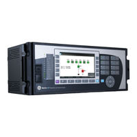
GE F35 Instruction Manual (682 pages)
Multiple Feeder Protection System
Brand:
GE
| Category:
Protection Device
| Size: 23.4 MB
Table of Contents
Table of Contents
3
1 Introduction
9
Safety Symbols and Definitions
9
General Cautions and Warnings
9
For Further Assistance
10
2 Product Description
13
Description
14
Security
15
Order Codes
18
Order Codes with Enhanced CT/VT Modules
19
Order Codes with Process Bus Modules
22
Replacement Modules
25
Signal Processing
28
UR Signal Processing
28
Specifications
30
Protection Elements
30
User-Programmable Elements
33
Monitoring
35
Metering
36
Inputs
37
Power Supply
38
Outputs
39
Communications
41
Inter-Relay Communications
42
Cybersentry Security
43
Graphical Front Panel
43
Environmental
44
Type Tests
45
Production Tests
45
Approvals
46
Maintenance
46
3 Installation
47
Unpack and Inspect
47
Panel Cutouts
48
Horizontal Units
48
Vertical Units
51
Rear Terminal Layout
56
Wiring
58
Typical Wiring
58
Dielectric Strength
59
Control Power
59
CT/VT Modules
60
Process Bus Modules
62
Contact Inputs and Outputs
62
Transducer Inputs and Outputs
73
RS232 Port
75
CPU Communication Ports
76
Irig-B
78
Direct Input and Output Communications
79
Description
79
Fiber: LED and ELED Transmitters
82
Fiber Laser Transmitters
82
Interface
83
RS422 Interface
87
RS422 and Fiber Interface
89
And Fiber Interface
90
IEEE C37.94 Interface
90
C37.94SM Interface
93
Activate Relay
96
Install Software
97
Enervista Communication Overview
97
System Requirements
98
Install Software
99
Add Device to Software
100
Set IP Address in UR
100
Configure Serial Connection
105
Configure Ethernet Connection
106
Configure Modem Connection
108
Automatic Discovery of UR Devices
108
Connect to the F35
109
Connect to the F35 in Enervista
109
Use Quick Connect Via the Front Panel RS232 Port
110
Use Quick Connect Via a Rear Ethernet Port
111
Set up Cybersentry and Change Default Password
112
Import Settings
112
Connect to D400 Gateway
113
Oscillography Files
113
Event Records
113
Log Files
113
Setting Files
114
4 Interfaces
115
Enervista Software Interface
115
Introduction
115
Settings Files
115
Event Viewing
116
File Support
117
Enervista Main Window
117
Protection Summary Window
118
Settings Templates
119
Secure and Lock Flexlogic Equations
123
Settings File Traceability
126
Front Panel Interface
128
Front Panel
128
Front Panel Display
131
Front Panel Navigation Keys
152
LED Indicators
154
Front Panel Labelling
158
Menu Navigation
165
Change Settings
167
View Actual Values
172
Breaker Control
173
Change Passwords
174
Logic Diagrams
176
Invalid Password Entry
176
Flexlogic Design Using Engineer
177
Design Logic
179
Send File to and from Device
189
Monitor Logic
190
View Front Panel and Print Labels
191
Generate Connectivity Report
192
Preferences
192
Toolbars
196
5 Settings
203
Settings Menu
203
Overview
206
Introduction to Elements
206
Introduction to AC Sources
207
Product Setup
209
Security
209
Display Properties
227
Graphical Front Panel
229
Clear Relay Records
241
Communications
242
Modbus User Map
347
Real Time Clock
348
Fault Reports
352
Oscillography
354
Data Logger
356
Demand
358
User-Programmable Leds
359
User-Programmable Self-Tests
363
Control Pushbuttons
364
User-Programmable Pushbuttons
365
Flex State Parameters
371
User-Definable Displays
372
Direct Inputs and Outputs
374
Teleprotection
380
Remote Resources
381
Remote Resources Configuration
381
AC Inputs
383
System Setup
383
Power System
384
Signal Sources
385
Breakers
388
Disconnect Switch Control
393
Flexcurves
398
Flexlogic
405
Flexlogic Operands
405
Flexlogic Rules
417
Flexlogic Evaluation
418
Flexlogic Example
418
Flexlogic Equation Editor
423
Flexlogic Timers
423
Flexelements
423
Non-Volatile Latches
428
Grouped Elements
429
Overview
429
Setting Group 1
429
Phase Current
430
Neutral Current
439
Wattmetric Ground Fault
442
Ground Current
446
Negative Sequence Current
449
Voltage Elements
451
Control Elements
458
Overview
458
Trip Bus
458
Setting Groups
460
Selector Switch
461
Underfrequency (ANSI 81U)
468
Autoreclose (ANSI 79)
469
Digital Elements
476
Digital Counters
479
8-Bit Switches
481
Monitoring Elements
483
Cold Load Pickup
507
PID Regulator
508
Inputs/Outputs
511
Contact Inputs
511
Virtual Inputs
513
Contact Outputs
514
Virtual Outputs
517
Resetting
517
Direct Inputs and Outputs
518
Teleprotection
522
Transducer Inputs/Outputs
524
Dcma Inputs
524
RTD Inputs
525
Dcma Outputs
526
Testing
530
Test Mode Function
530
Test Mode Forcing
530
Force Contact Inputs
531
Force Contact Outputs
531
Advertisement
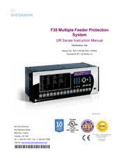
GE F35 Instruction Manual (554 pages)
Multiple Feeder Protection System, UR Series
Brand:
GE
| Category:
Protection Device
| Size: 10.72 MB
Table of Contents
Table of Contents
5
1 Getting Started
13
Important Procedures
13
Cautions and Warnings
13
Inspection Checklist
14
Ur Overview
15
Introduction to the Ur
15
Hardware Architecture
16
Software Architecture
17
Important Concepts
17
Enervista Ur Setup Software
18
Pc Requirements
18
Installation
18
Configuring the F35 for Software Access
19
Using the Quick Connect Feature
22
Connecting to the F35 Relay
28
Ur Hardware
29
Mounting and Wiring
29
Communications
29
Faceplate Display
29
Using the Relay
30
Faceplate Keypad
30
Menu Navigation
30
Menu Hierarchy
30
Relay Activation
30
Relay Passwords
31
Flexlogic™ Customization
31
Commissioning
32
2 Product Description
33
Introduction
33
Overview
33
Ordering
34
Replacement Modules
38
Specifications
41
Protection Elements
41
User-Programmable Elements
42
Monitoring
43
User-Programmable Pushbuttons
43
User-Definable Displays
43
Metering
44
Inputs
45
Direct Inputs/Outputs
45
Teleprotection
45
Power Supply
46
Outputs
46
Communications
48
Inter-Relay Communications
49
Environmental
50
Type Tests
51
Production Tests
51
Approvals
52
Maintenance
52
3 Hardware
53
Description
53
Panel Cutout
53
Module Withdrawal and Insertion
58
Rear Terminal Layout
60
Wiring
62
Typical Wiring
62
Dielectric Strength
63
Control Power
63
Ct/Vt Modules
64
Process Bus Modules
66
Contact Inputs and Outputs
66
Transducer Inputs/Outputs
78
Rs232 Faceplate Port
79
Cpu Communication Ports
79
Irig-B
83
Direct Input/Output Communications
84
Description
84
Fiber: Led and Eled Transmitters
87
Fiber-Laser Transmitters
87
Interface
88
Rs422 Interface
91
Rs422 and Fiber Interface
93
And Fiber Interface
93
Ieee C37.94 Interface
94
C37.94Sm Interface
97
Managed Ethernet Switch Modules
100
Overview
100
Managed Ethernet Switch Module Hardware
100
Managed Switch Led Indicators
101
Configuring the Managed Ethernet Switch Module
101
Uploading F35 Switch Module Firmware
104
Ethernet Switch Self-Test Errors
106
4 Human Interfaces
107
Enervista Ur Setup Software Interface
107
Introduction
107
Creating a Site List
107
Enervista Ur Setup Overview
107
Enervista Ur Setup Main Window
109
Extended Enervista Ur Setup Features
110
Settings Templates
110
Securing and Locking Flexlogic™ Equations
114
Settings File Traceability
116
Faceplate Interface
119
Faceplate
119
Led Indicators
120
Custom Labeling of Leds
123
Display
129
Keypad
129
Breaker Control
129
Menus
130
Changing Settings
132
5 Settings
133
Installation
133
Overview
137
Settings Main Menu
137
System Setup
137
Ac Inputs
137
Power System
137
Signal Sources
138
Introduction to Elements
140
Introduction to Ac Sources
141
Product Setup
144
Security
144
Display Properties
148
Clear Relay Records
150
Communications
151
Modbus User Map
173
Real Time Clock
174
Fault Reports
175
Oscillography
177
Data Logger
179
Demand
181
User-Programmable Leds
182
User-Programmable Self Tests
185
Control Pushbuttons
186
Breakers
211
Disconnect Switches
215
Flexcurves
218
Flexlogic
225
Introduction to Flexlogic
225
Flexlogic™ Rules
234
Flexlogic™ Evaluation
234
Flexlogic™ Example
235
Flexlogic Equation Editor
239
Flexlogic Timers
239
Flexelements
241
Non-Volatile Latches
245
Grouped Elements
246
Overview
246
Setting Group
246
Phase Current
246
Neutral Current
255
Ground Current
257
Negative Sequence Current
259
Voltage Elements
262
Control Elements
268
Overview
268
Trip Bus
268
Setting Groups
270
Selector Switch
271
Underfrequency
277
Autoreclose
278
Digital Elements
284
Digital Counters
287
8-Bit Switches
289
Monitoring Elements
291
Pid Regulator
297
Inputs and Outputs
300
Contact Inputs
300
Virtual Inputs
302
Contact Outputs
303
Virtual Outputs
305
Remote Devices
306
Remote Inputs
307
Remote Double-Point Status Inputs
308
Remote Outputs
308
Resetting
309
Direct Inputs and Outputs
310
Teleprotection Inputs and Outputs
313
Iec 61850 Goose Analogs
315
Iec 61850 Goose Integers
316
Transducer Inputs and Outputs
318
Rtd Inputs
318
Dcma Outputs
320
Testing 5.10.1 Test Mode
325
Force Contact Inputs
325
Force Contact Outputs
325
6 Actual Values
327
Overview
327
Actual Values Main Menu
327
Status
327
Contact Inputs
329
Virtual Inputs
329
Remote Inputs
329
Remote Double-Point Status Inputs
330
Teleprotection Inputs
330
Contact Outputs
330
Virtual Outputs
331
Autoreclose
331
Remote Devices
331
Selector Switches
332
Flex States
332
Digital Counters
332
Ethernet
333
Direct Inputs
333
Direct Devices Status
334
Iec 61850 Goose Integers
334
Egd Protocol Status
334
Teleprotection Channel Tests
335
Incipient Fault Detector
335
Ethernet Switch
336
Metering Conventions
337
Sources
340
Tracking Frequency
345
Flexelements
346
Iec 61580 Goose Analog Values
346
Transducer Inputs/Outputs
347
Records
348
Fault Reports
348
Event Records
348
Oscillography
349
Data Logger
349
Breaker Maintenance
350
Product Information
351
Model Information
351
Firmware Revisions
351
7 Commands and
353
Commands
353
Commands Menu
353
Virtual Inputs
353
Clear Records
354
Set Date and Time
354
Relay Maintenance
355
Targets Menu
356
Target Messages
356
Relay Self-Tests
356
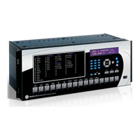
GE F35 Instruction Manual (570 pages)
Multiple Feeder Protection System
Brand:
GE
| Category:
Protection Device
| Size: 19.79 MB
Table of Contents
Table of Contents
3
1 Introduction
9
Safety Symbols and Definitions
9
General Cautions and Warnings
9
For Further Assistance
10
2 Product Description
13
Description
14
Security
15
Order Codes
18
Order Codes with Enhanced CT/VT Modules
19
Order Codes with Process Bus Modules
22
Replacement Modules
26
Signal Processing
28
UR Signal Processing
28
Specifications
30
Protection Elements
31
User-Programmable Elements
34
Monitoring
36
Metering
36
Inputs
37
Power Supply
39
Outputs
40
Communications
42
Inter-Relay Communications
43
Cybersentry Security
44
Environmental
44
Type Tests
45
Production Tests
45
Approvals
46
Maintenance
46
3 Installation
47
Unpack and Inspect
47
Panel Cutouts
48
Horizontal Units
48
Vertical Units
49
Rear Terminal Layout
54
Wiring
55
Typical Wiring
55
Dielectric Strength
56
Control Power
56
CT/VT Modules
57
Process Bus Modules
59
Contact Inputs and Outputs
59
Transducer Inputs and Outputs
66
RS232 Faceplate Port
68
CPU Communication Ports
69
Irig-B
71
Direct Input and Output Communications
72
Description
72
Fiber: LED and ELED Transmitters
75
Fiber Laser Transmitters
75
Interface
76
RS422 Interface
80
RS422 and Fiber Interface
82
And Fiber Interface
83
IEEE C37.94 Interface
83
C37.94SM Interface
86
Activate Relay
89
Install Software
90
Enervista Communication Overview
90
System Requirements
91
Install Software
92
Add Device to Software
93
Set IP Address in UR
93
Configure Serial Connection
99
Configure Ethernet Connection
100
Configure Modem Connection
102
Automatic Discovery of UR Devices
102
Connect to the F35
103
Connect to the F35 in Enervista
103
Use Quick Connect Via the Front Panel RS232 Port
104
Set up Cybersentry and Change Default Password
105
Import Settings
106
4 Interfaces
109
Enervista Software Interface
109
Introduction
109
Settings Files
109
Event Viewing
110
File Support
111
Enervista Main Window
111
Protection Summary Window
112
Settings Templates
113
Secure and Lock Flexlogic Equations
117
Settings File Traceability
120
Front Panel Interface
123
Front Panel Display
123
Front Panel Keypad
124
Menu Navigation
124
Menu Hierarchy
124
Changing Settings
125
Faceplate
127
LED Indicators
128
Custom LED Labeling
132
Breaker Control
137
Change Passwords
138
Invalid Password Entry
139
Logic Diagrams
140
Flexlogic Design and Monitoring Using Engineer
141
Design Logic
143
Send File to and from Device
153
Monitor Logic
154
View Front Panel and Print Labels
155
Generate Connectivity Report
156
Preferences
156
Toolbars
160
5 Settings
167
Settings Menu
167
Overview
170
Introduction to Elements
170
Introduction to AC Sources
171
Product Setup
173
Security
173
Display Properties
191
Clear Relay Records
193
Communications
194
Modbus User Map
260
Real Time Clock
260
Fault Reports
264
Oscillography
266
Data Logger
268
Demand
270
User-Programmable Leds
271
User-Programmable Self-Tests
274
Control Pushbuttons
275
User-Programmable Pushbuttons
276
Flex State Parameters
281
User-Definable Displays
282
Direct Inputs and Outputs
284
Teleprotection
290
Installation
291
Remote Resources
291
Remote Resources Configuration
291
System Setup
293
AC Inputs
293
Power System
294
Signal Sources
295
Breakers
298
Disconnect Switches
302
Flexcurves
305
Flexlogic
312
Flexlogic Operands
312
Flexlogic Rules
323
Flexlogic Evaluation
323
Flexlogic Example
324
Flexlogic Equation Editor
329
Flexlogic Timers
329
Flexelements
329
Non-Volatile Latches
333
Grouped Elements
334
Overview
334
Setting Group 1
334
Phase Current
334
Neutral Current
334
Wattmetric Ground Fault
334
Ground Current
351
Negative Sequence Current
354
Voltage Elements
356
Control Elements
363
Overview
363
Trip Bus
363
Setting Groups
365
Selector Switch
366
Underfrequency (ANSI 81U)
373
Autoreclose (ANSI 79)
374
Digital Elements
381
Digital Counters
384
8-Bit Switches
386
Monitoring Elements
388
Cold Load Pickup
411
PID Regulator
412
Inputs/Outputs
415
Contact Inputs
415
Virtual Inputs
417
Contact Outputs
418
Virtual Outputs
421
Resetting
421
Direct Inputs and Outputs
422
Teleprotection
425
Transducer Inputs/Outputs
427
Dcma Inputs
427
RTD Inputs
428
Dcma Outputs
429
Testing
433
Test Mode Function
433
Test Mode Forcing
433
Force Contact Inputs
434
Force Contact Outputs
434
Advertisement
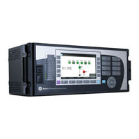
GE F35 Instruction Manual (456 pages)
Multiple Feeder Protection System
Brand:
GE
| Category:
Protection Device
| Size: 9 MB
Table of Contents
Table of Contents
3
1 Introduction
9
Safety Symbols and Definitions
9
General Cautions and Warnings
9
For Further Assistance
10
2 Product Description
11
Security
13
Order Codes
16
Order Codes with Enhanced CT/VT Modules
17
Order Codes with Process Bus Modules
20
Replacement Modules
22
Specifications
24
Protection Elements
24
User-Programmable Elements
27
Monitoring
29
Metering
29
Inputs
30
Power Supply
32
Outputs
32
Communications
35
Inter-Relay Communications
36
Environmental
37
Type Tests
38
Production Tests
38
Approvals
39
Maintenance
39
3 Installation
41
Unpack and Inspect
41
Panel Cutouts
42
Horizontal Units
42
Vertical Units
43
Rear Terminal Layout
47
Wiring
49
Typical Wiring
49
Dielectric Strength
50
Control Power
50
CT/VT Modules
51
Process Bus Modules
52
Contact Inputs and Outputs
53
Transducer Inputs and Outputs
60
RS232 Faceplate Port
62
CPU Communication Ports
62
Irig-B
64
Direct Input and Output Communications
65
Description
65
Fiber: LED and ELED Transmitters
67
Fiber Laser Transmitters
67
Interface
68
RS422 Interface
72
RS422 and Fiber Interface
74
And Fiber Interface
74
IEEE C37.94 Interface
75
C37.94SM Interface
78
Activate Relay
81
Install Software
82
Enervista Communication Overview
82
System Requirements
83
Install Software
83
Configure the F35 for Software Access
84
Configure Serial Communication
85
Configure Ethernet Communication
86
Automatic Discovery of UR Devices
87
Connect to the F35
87
Connect to the F35 in Enervista
87
Use Quick Connect Via the Front Panel RS232 Port
88
Use Quick Connect Via a Rear Ethernet Port
89
Set up Cybersentry and Change Default Password
94
4 Interfaces
97
Enervista Software Interface
97
Introduction
97
Settings Files
97
Event Viewing
98
File Support
98
Enervista Main Window
98
Settings Templates
99
Secure and Lock Flexlogic Equations
104
Settings File Traceability
106
Front Panel Interface
108
Front Panel Display
108
Front Panel Keypad
108
Menu Navigation
109
Menu Hierarchy
109
Changing Settings
110
Faceplate
111
LED Indicators
113
Custom LED Labeling
116
Breaker Control
122
Change Passwords
123
Invalid Password Entry
124
Logic Diagrams
125
5 Settings
127
Settings Menu
127
SETTINGS 5.1 Settings Menu
127
Overview
130
Introduction to Elements
130
Introduction to AC Sources
131
Product Setup
133
Security
133
Display Properties
151
Clear Relay Records
153
Communications
154
Modbus User Map
207
Real Time Clock
208
Fault Reports
212
Oscillography
214
Data Logger
216
Demand
217
User-Programmable Leds
219
User-Programmable Self-Tests
222
Control Pushbuttons
223
User-Programmable Pushbuttons
224
Flex State Parameters
229
User-Definable Displays
230
Direct Inputs and Outputs
232
Teleprotection
239
Installation
240
Remote Resources
240
Remote Resources Configuration
240
AC Inputs
241
System Setup
241
Power System
243
Signal Sources
244
Breakers
246
Disconnect Switches
251
Flexcurves
254
Flexlogic
261
Flexlogic Operands
261
Flexlogic Rules
270
Flexlogic Evaluation
270
Flexlogic Example
271
Flexlogic Equation Editor
276
Flexlogic Timers
276
Flexelements
276
Non-Volatile Latches
280
Overview
281
Setting Group 1
281
Grouped Elements
281
Phase Current
282
Neutral Current
290
Wattmetric Ground Fault
292
Ground Current
296
Negative Sequence Current
299
Voltage Elements
301
Control Elements
306
Overview
306
Trip Bus
306
Setting Groups
308
Selector Switch
309
Underfrequency
316
Autoreclose
317
Digital Elements
323
Digital Counters
325
8-Bit Switches
327
Monitoring Elements
328
PID Regulator
342
Inputs/Outputs
344
Contact Inputs
344
Virtual Inputs
346
Contact Outputs
347
Virtual Outputs
350
Resetting
350
Direct Inputs and Outputs
351
Teleprotection
354
Transducer Inputs/Outputs
356
Dcma Inputs
356
RTD Inputs
357
Dcma Outputs
358
Testing
361
Test Mode Function
361
Test Mode Forcing
362
Force Contact Inputs
363
Force Contact Outputs
363
GE F35 Communications Manual (532 pages)
Universal Relay Family
Brand:
GE
| Category:
Relays
| Size: 3.79 MB
Table of Contents
Table of Contents
3
1 Introduction
7
Products
7
Features Per Product
7
Communication Ports
20
Safety Symbols and Definitions
20
For Further Assistance
20
Modbus
21
2 Modbus Communication
21
Modbus RTU Protocol
21
Introduction
21
Configuration
21
Physical Layer
21
Data Link Layer
22
Modbus RTU CRC-16 Algorithm
23
Modbus Function Codes
24
Supported Function Codes
24
Read Actual Values or Settings (Function Code 03/04H)
24
Execute Operation (Function Code 05H)
25
Store Single Setting (Function Code 06H)
25
Store Multiple Settings (Function Code 10H)
26
Exception Responses
26
File Transfers
27
Obtaining Relay Files Using Modbus
27
Memory Map
32
Modbus Memory Map
32
6 Iec 60870-5-104
80
Communication
81
Data Formats
204
3 Iec 61850 Communication
239
Overview
239
Introduction
239
Abstract Communication Service Interface (ASCI)
241
Datasets
244
Txgoose
245
Rxgoose
247
Reports
248
Commands
250
Substation Configuration Language (SCL)
250
Configuring the UR Using SCL
256
Merge SCL File
261
Configurable Logical Devices
262
Protocol Implementation Conformance Statement (PICS)
262
Basic Conformance Statement
262
ACSI Conformance Statement
263
ACSI Basic Conformance Statement
263
ACSI Models Conformance Statement
263
ACSI Services Conformance Statement
265
Model Implementation Conformance Statement (MICS)
267
Master (Root) Logical Device
268
Protection (Prot) Logical Device
275
Control (Ctrl) Logical Device
354
System Logical Device
389
Meter Logical Device
410
General (Gen) Logical Device
431
GE Namespace
447
Enumerations
462
SCL Implementation Conformance Statement (SICS)
463
PIXIT Conformance Statement
465
TICS Conformance Statement
470
SCL Logging
472
Overview of Process
472
SCL File Storage on UR
473
Generation of CID Files
473
Schema Version Used by Ur/Enervista
473
CID File Processing Steps
473
SCL Log File Format and Examples
473
Troubleshooting Log File Errors
475
G2 Implementation Model for GOOSE Configuration Via SCL
475
Introduction
475
Configuration Process
476
Configuration Process with IED Setup Tool
478
IED Capability Description (ICD) File
478
Instantiated IED Capability Description (IID) File
482
Configured IED Description (CID) File
482
Sample SCL Files
484
Annex - Optional Intermediate GOOSE Reception Objects
489
E3-2.0 Implementation Model for GOOSE Configuration Via SCL
492
Introduction
492
Workflow
492
ICD Files
493
CID Files
494
IID Files
495
GE F35 Communications Manual (526 pages)
UR Family
Brand:
GE
| Category:
Controller
| Size: 3.78 MB
Table of Contents
Table of Contents
3
1 Introduction
7
Products
7
Features Per Product
7
Communication Ports
20
Safety Symbols and Definitions
20
For Further Assistance
20
Modbus
21
2 Modbus Communication
21
Modbus RTU Protocol
21
Introduction
21
Configuration
21
Physical Layer
21
Data Link Layer
22
Modbus RTU CRC-16 Algorithm
23
Modbus Function Codes
24
Supported Function Codes
24
Read Actual Values or Settings (Function Code 03/04H)
24
Execute Operation (Function Code 05H)
25
Store Single Setting (Function Code 06H)
25
Store Multiple Settings (Function Code 10H)
26
Exception Responses
26
File Transfers
27
Obtaining Relay Files Using Modbus
27
Memory Map
32
Modbus Memory Map
32
6 Iec 60870-5-104
80
Communication
81
Data Formats
203
3 Iec 61850 Communication
239
Overview
239
Introduction
239
Abstract Communication Service Interface (ASCI)
241
Datasets
244
Txgoose
245
Rxgoose
247
Reports
248
Commands
250
Substation Configuration Language (SCL)
250
Configuring the UR Using SCL
256
Merge SCL File
261
Configurable Logical Devices
262
Protocol Implementation Conformance Statement (PICS)
262
Basic Conformance Statement
262
ACSI Conformance Statement
263
ACSI Basic Conformance Statement
263
ACSI Models Conformance Statement
263
ACSI Services Conformance Statement
265
Model Implementation Conformance Statement (MICS)
267
Master (Root) Logical Device
268
Protection (Prot) Logical Device
275
Control (Ctrl) Logical Device
351
System Logical Device
385
Meter Logical Device
406
General (Gen) Logical Device
426
GE Namespace
442
Enumerations
457
SCL Implementation Conformance Statement (SICS)
458
PIXIT Conformance Statement
460
TICS Conformance Statement
465
SCL Logging
467
Overview of Process
467
SCL File Storage on UR
468
Generation of CID Files
468
Schema Version Used by Ur/Enervista
468
CID File Processing Steps
468
SCL Log File Format and Examples
468
Troubleshooting Log File Errors
470
G2 Implementation Model for GOOSE Configuration Via SCL
470
Introduction
470
Configuration Process
471
Configuration Process with IED Setup Tool
473
IED Capability Description (ICD) File
473
Instantiated IED Capability Description (IID) File
477
Configured IED Description (CID) File
477
Sample SCL Files
479
Annex - Optional Intermediate GOOSE Reception Objects
484
E3-2.0 Implementation Model for GOOSE Configuration Via SCL
487
Introduction
487
Workflow
487
ICD Files
488
CID Files
489
IID Files
490
Advertisement
Related Products
GE F60 UR Series
GE LOGIQ F3
GE FHQ7SWWW
GE FUF20S
GE FUF14SMRWW
GE FUF17SMRWW
GE ARITECH FP400 Series
GE FEX
GE FHV7SW
GE FP9
GE Categories
Refrigerator
Ranges
Microwave Oven
Air Conditioner
Dishwasher
More GE Manuals
Login
Sign In
OR
Sign in with Facebook
Sign in with Google
Upload manual
Upload from disk
Upload from URL