Sign In
Upload
Manuals
Brands
GE Manuals
Touch terminals
D20
GE D20 Manuals
Manuals and User Guides for GE D20. We have
2
GE D20 manuals available for free PDF download: Installation And Operation Manual, Technical Overview
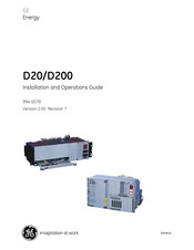
GE D20 Installation And Operation Manual (133 pages)
Brand:
GE
| Category:
Touch terminals
| Size: 0.96 MB
Table of Contents
Table of Contents
3
Product Support and Safety
4
About this Guide
12
Installation Steps
13
Getting Started: Required Steps
13
Installation Tools, Equipment and Accessories
14
What Are the D20 and D200?
15
Separate Peripherals
15
Assembling a D20
15
Familiarization
15
Chassis Compatibility
16
D20 Kit Components
16
Table
16
D20 Chassis
16
Other Components
17
Other System Configurations
17
D20 Front Panel: Non-VME Single Slot
18
D20 Front Panel: VME Multi Slot
18
D20 Rear Panel: Non-VME
19
D20 Rear Panel: VME
19
WESTERM D20M+ Termination Panel
20
D200
21
D200 Front Panel
22
D200 Rear Panel
23
WESTERM D20M++ Termination Panel
24
LED Indicators
26
D20ME: Four Versions
26
D20ME Main Module
26
Enhanced Feature: 68K Monitor Speed Change
27
D20ME/ME II Factory Fitted Software
27
D20ME: Serial I/O Architecture
27
Serial Performance
27
D20: Supplying Power
28
D20 Power Supply
28
External Power Supplies
28
Redundant Power Supplies
28
Standard Power Supplies
29
D20/D200 Overcurrent Protection
29
I/O Peripherals
30
WESMAINT Cable
30
Third-Party Modems
30
Modems
30
Hot-Swap Peripherals
31
I/O Peripheral Module Assembly
31
D20A Analog Input Peripheral
32
D20S Digital Input Peripheral
32
D20K Control Output Peripheral
32
D20C Combination I/O Peripheral
33
D20C Daughter Boards
33
Table: D20C Options
33
D20AC Analog Input Peripheral
33
Promaint
34
D.20 Peripheral Link
34
Second D.20 Link
34
D.20 RS-485 Interface
35
Extended Communications
35
D.20 Splitter
35
D.20 Comm Interface
35
Interposing Relays
36
Universal Protocol Converter
36
D20Eme
37
Applications of the D20EME
37
Upgrades and Replacements
37
Table: Chassis Compatibility
37
D20EME Kit Components
38
Table: Available Options
38
Ethernet Capability
40
Media Interface Cards
40
Interconnect Cable
40
D20/D200 Redundancy
41
Failover Sequence
41
D20/D200 Redundancy Failover
42
RS-232 Switch Panel: Indicators
42
Active/Standby Switch
42
RS-232 Switch Panel: Connectors
43
D20ME Main Module: Board Layout
44
Connections and Configuration
44
D20ME Jumpering
45
D20ME Jumper Options
45
JP2 - VME Address
45
JP3-1 and JP3-2 RTC Options
45
Other Jumpers
46
JP8 – Battery Backup Enable/Disable
46
JP4 - Watchdog
46
D20ME II Board Layout
47
D20ME II Jumpering
47
Table: VME Jumper Options
48
Single Node
48
Multi-Node
48
JP1 - VME Control
49
Table: JP4 - Watchdog Enable/Disable
49
Table: JP8 – Battery Backup Enable/Disable
49
Sw1 Rs-485 2W/4W
50
SW2 RS-485/RS-232 Mode Selection
50
JP11 RS-232/RS-485 Operation
51
Table: Serial Port Pinouts
51
Transient Suppression
52
2-Wire RS-485 Cable
52
4-Wire RS-485 Cable
52
D20ME/ME II Power Connections
53
D200 Power Supply
53
Procedure
53
Termination Panels: Jumper Settings
55
Termination Panels: Power Supply
55
WESTERM D20M+SS: Power Supply
55
WESTERM D20M++: Power Supply
56
Peripherals: Supplying Power
56
Peripherals: Connect for Power Using D.20 Link Procedure
57
Table: J1 Pinouts on WESTERM Peripherals
57
WESTERM D20S: External DC Supply
58
WESTERM D20A: External Loop Supply
58
WESTERM D20K: External Control Output Supply
59
WESTERM D20C: External DC and Control Output Supply
60
WESTERM D20AC: DC Power Supply
61
D.20 Interface Modules: DC Power Supply
62
D.20 Interface Modules: Connect for Power Using D.20 Link
63
Table: J1 Pinouts on D.20 Interface Modules
63
I/O Peripheral Boards: Jumper Settings
64
WESDAC Board Jumpers
65
WESDAC Jumpers Z1-Z5
65
Checking the Base Version
65
WESDAC Jumper Settings
66
WESTERM Addressing: Jumper Z1
67
WESTERM D20A: Jumpers
68
WESTERM D20A: Jumper Settings
68
WESTERM D20S: Jumpers
69
WESTERM D20S: Settings
70
WESTERM D20K: Jumpers
71
WESTERM D20K: Settings
72
WESTERM D20C: Jumpers
73
WESTERM D20C: Settings
74
D.20 Interface Modules
76
D.20 Comm Interface: Jumpers
76
D.20 Comm Interface: Settings
77
D.20 Splitter: Jumpers
78
D.20 Splitter: Settings
78
D.20 RS-485 Adaptor: Settings
79
D.20 RS-485 Adaptor: Jumpers
79
D.20 DC Interface: Settings
80
D.20 DC Interface: Jumpers
80
EME Main Board Jumper and Component Locations
81
Table: Main Components
82
D20EME Leds
82
Memory Expansion Card
82
MIC Jumper Options
83
10BASE-T MIC Jumper Settings
83
10BASE2 MIC Jumper Settings
83
10BASE-FL MIC Jumper Settings
84
10BASE-FL Fiber Cable Connectors
84
Redundant D20/D200 Systems
85
Redundant System: Software Configuration
86
Required Components
86
Redundant System: Mounting the Hardware
86
Procedure: Installing Watchdog Cables
87
Procedure: Installing a Ping Cable
87
Installing an HDLC Cable
88
Selecting an HDLC Port
88
Connecting Serial Communication Cables
88
Serial Port Pin-Outs
88
Redundant Multi-Node Systems: Example
89
Testing Redundancy
90
WESMAINT Cable Pinouts
90
Power-Up and Test D20/D200
91
Required for Testing
91
68K Monitor
92
Accessing WESMAINT II+ Using a Terminal
92
Procedure: Set up Terminal
93
Procedure: Powering-Up the D20
94
Software Corruption on Power-Up
94
Procedure: Workaround
94
On-Line Start-Up Test
96
Code and Configuration Files
96
D20 and D200 Software: Introduction
101
When to Download
101
D20/D200 Software Configuration
101
Identification of Base Type
102
Alternate Identification Method
102
Prerequisites for Code Download
102
D20ME: Flash Memory
103
Setup WESMAINT II+ Terminal
103
Procedure: Identify Base
103
Procedure: Code Download D20 Base
104
Result: Code File Load Completed
106
Procedure: Code Download CCU Base
107
Configuration File Download
109
Multi-Node Downloads
109
Serial Download
110
Table: Identify the D20ME II Type
110
Upgrading
111
From D20M or 1 MB Flash D20ME?
111
Procedure: D20ME II -D20 Base
112
Procedure: D20ME II - CCU
114
D20EME Ethernet Interface
116
About Multi-Node Downloads
116
D20EME Global Memory Expansion
116
D20ME/ME II Main Board
117
I/O Peripherals Common LEDS
117
Operation
117
Leds Vs. MCU Status
118
D20 Power Supply Leds
118
Media Interface Cards LED Indicators
119
RS-232 Switch Panel: Active/Standby Switch Operation
119
D20/D200 Maintenance
120
D20 Power Supply Fuses
120
Replaceable Fuses
120
Servicing
120
Fuse Locations: D200
121
Cleaning and Handling of Batteries
122
Batteries
122
Battery Checking
122
Recycling of Batteries
123
Procedure: Change Battery
123
Introduction
124
Compatibility
124
Appendix A: Product Combinations
124
D.20 Input/Output Peripheral Compatibility
126
Changing the Baud Rate
129
SET BAUD RATE Command
129
Appendix B: 68K Monitor Commands
129
Supported Speeds
130
Advertisement
GE D20 Technical Overview (108 pages)
Remote Terminal Unit
Brand:
GE
| Category:
Touch terminals
| Size: 1.98 MB
Table of Contents
About this Document
9
Who Should Use this Document
10
Product Support
11
What's New
12
D20EME (Ethernet/Memory Expansion)
13
D20 High-Voltage Peripherals
14
Multiple Language Support
15
System Overview
16
System Architecture
17
D20/D200 Product Comparison
18
Figure 4 D20 System Architecture
19
Figure 5 Example D20 Rack Layout
20
D200 Substation Automation Platform
21
Figure 7 D200 System Architecture
22
Figure 8 Example D200 Rack Layout
23
D20/D200 RTU Hardware
24
Main Processor
25
Figure 11 D20ME II Main Processor
26
Ethernet/Memory Expansion (EME) Kit
27
Modems
28
Auxiliary Equipment
29
Firmware
30
Detailed Technical Description
33
Enclosure
34
Figure 15 D20 Chassis (Non-VME Version)
35
Peripheral I/O Module Assembly
36
Environmental
37
Main Processor
38
D20/D200 Main Processor Specifications
39
Firmware
40
Time Synchronization
42
Figure 20 D20/D200 Time Synchronization
43
Ethernet/Memory Expansion (EME) Kit
44
I/O Peripheral Modules
45
Termination Types
46
Figure 25 D20 I/O Peripheral – Disconnect Termination
47
Hardware
48
Firmware
49
I/O Processing
51
D20S Digital Input Peripheral
52
Figure 29 D20S Digital Input Peripheral Block Diagram
53
Table 8 D20S Specifications
55
D20A Analog Input Peripheral
56
Figure 31 D20A Analog Input Peripheral Block Diagram
57
Figure 33 Three-Point Linearity Correction
59
Table 10 D20A Specifications
60
D20K Control Output Peripheral
61
Table 12 D20K Specifications
64
Interposing Relay Panel
65
Figure 35 Interposing Relays
66
D20C Combination I/O Peripheral
67
Table 16 D20C Specifications
68
Table 17 D20C Options
69
D20AC, AC Analog Input Peripheral
70
Table 19 D20AC Options
71
D20/D200 Power Supplies and Chargers
72
D20 Power Supply Specifications
73
D20 Battery Chargers
74
D20 Modems
75
WESDAC 202/V.23 Modem Specifications
76
Communications
77
D.20 Link
78
Designing a Distributed D20 Network
79
D.20 Communication Interface
80
Adapter Modules
81
Communication Cables
82
Power Requirements
83
D20/D200 Redundancy
84
D.20 Link Redundancy
85
Auxiliary Equipment
86
Data Display Panel
87
Configuration and Maintenance Software
88
Promaint
89
Application Software
90
Communication Services Applications
91
Data Conversion Applications
92
Frequently Asked Questions
93
What Is the I/O Capacity of a D20 System
94
A. Specifications and Supported Standards
95
B. Supported Host Protocols
98
C. Supported IED Protocols
99
D. Power Consumption – D20 Modules
100
E. D20/D200 Main Processor Compatibility
101
F. D.20 Link Installation
102
Advertisement
Related Products
GE D200
GE Spacemaker D2092P129
GE D20MX
GE D.20 RIO
GE D25
GE D20 ME
GE D2
GE D20A6
GE Multilin D20E
GE DBXR463GGWW
GE Categories
Refrigerator
Ranges
Microwave Oven
Air Conditioner
Dishwasher
More GE Manuals
Login
Sign In
OR
Sign in with Facebook
Sign in with Google
Upload manual
Upload from disk
Upload from URL