Sign In
Upload
Manuals
Brands
GE Manuals
Protection Device
339
GE 339 Manuals
Manuals and User Guides for GE 339. We have
3
GE 339 manuals available for free PDF download: Communications Manual, Instruction Manual
GE 339 Communications Manual (786 pages)
Protective Relay Platform
Brand:
GE
| Category:
Relays
| Size: 17.76 MB
Table of Contents
Table of Contents
5
Communications Interfaces
9
Rs485 Interface
11
Electrical Interface
11
MODBUS Protocol
12
Data Frame Format and Data Rate
12
Data Packet Format
12
Error Checking
13
CRC-16 Algorithm
13
Timing
14
Series Supported Functions
14
DNP Communication
15
DNP Protocol Settings
15
DNP Device Profile
16
DNP Implementation
18
DNP Serial Enervista Setup
22
DNP General
24
IEC 60870-5-103 Serial Communication
26
Interoperability
26
Physical Layer
26
Link Layer
27
Application Layer
27
Application Level
31
Type Identification
31
Function Type
32
Information Number
32
Data Management
33
Digital States
33
Measurands
33
MODBUS Memory Map
33
Commands
35
103 General Settings
35
Ethernet Interface
37
Redundancy Options
37
Parallel Redundancy Protocol (PRP)
39
High-Availability Seamless Redundancy (HSR)
40
350 Daisy Chain
41
LLA (Link Loss Alert)
42
Sntp
43
SNTP Settings
43
SNTP Modes
43
Modbus Tcp/Ip
44
Data and Control Functions
44
Request Response Sequence
45
Exception and Error Responses
45
DNP Communication
46
DNP Ethernet Protocol Settings
46
DNP Device Profile
47
Format Codes
47
DNP Port Allocation
49
DNP Implementation
50
DNP Ethernet Enervista Setup
53
DNP General
55
IEC60870-5-104 Protocol
58
IEC 60870-5-104 Interoperability
58
IEC 60870-5-104 Protocol Settings
66
IEC 60870-5-104 Point Lists
67
Summary of Ethernet Client Connections
70
Series Iec61850 Goose
73
GOOSE Configuration Via the 3 Series Menus
74
Enervista 3 Series Setup Software Structure
75
GOOSE Transmission
77
GOOSE Rx
78
GOOSE Rx Status
79
GOOSE Rx Headers
81
GOOSE Receive Dataset Structure
82
GOOSE Remote Inputs
83
Using the Simplified GOOSE Configurator
85
Setting up the GOOSE Configurator
86
Connection
88
Configuration
88
Using the IEC 61850 Configurator
99
Introduction to the 3 Series IEC61850 Device Configurator
99
Series GOOSE Configuration - Lab
103
Configuration Lab Steps
105
IEC61850 Server
118
Functionality
120
IEC61850 Configurator
121
Online and Offline Setup
121
IEC 61850 Configurator Details
123
ICD/CID
123
Settings
124
Reports
127
GOOSE Reception and GOOSE Transmission
128
Opc-Ua Communication Standard
129
Definitions and Acronyms
129
OPC-UA Architecture
130
OPC-UA Server Configuration Data
130
OPC-UA Point Lists
131
Usb Interface
141
Data Frame Format and Data Rate
141
Data Packet Format
142
Error Checking
142
CRC-16 Algorithm
142
Timing
143
Series Supported Functions
144
Time Protocols
145
IEC 1588 Precision Time Protocol (PTP)
145
Real Time Clock
146
Function Code 03H
149
Function Code 04H
151
Function Code 05H
152
Function Code 06H
157
Function Code 07H
158
Function Code 08H
159
Performing Commands Using Function Code 10H
161
Function Code 42H
162
Error Responses
163
MODBUS User Map
165
Mics
719
Logical Nodes
722
Logical Nodes for Protection Functions. LN Group:p
723
Logical Nodes for Protection Related Functions. LN Group: R
737
Logical Nodes for Generic References. LN Group: G
742
Logical Nodes for Metering and Measurement. LN Group: M
745
Logical Nodes for Switchgear. LN Group: X
749
Common Data Class
750
Common Data Class Specifications for Measurand Information
755
Common Data Class Specifications for Controllable Status
763
Pics
769
ASCI Basic Conformance Statement
770
ACSI Models Conformance Statement
771
ACSI Service Conformance Statement
773
Pixit
776
PIXIT for Server Model
777
PIXIT for Data Set Model
778
PIXIT for Reporting Model
779
PIXIT for GOOSE Publish Model
780
PIXIT for GOOSE Subscribe Model
781
PIXIT for Control Model
782
PIXIT for Time Synchronisation Model
784
Manual Revision History
785
Advertisement
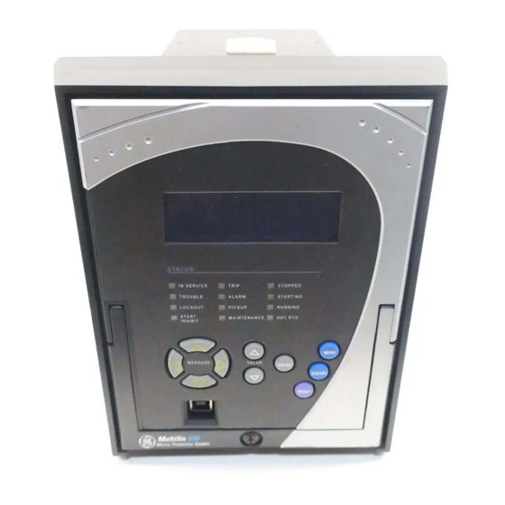
GE 339 Instruction Manual (342 pages)
Motor Protection System/Motor protection and control
Brand:
GE
| Category:
Protection Device
| Size: 15.34 MB
Table of Contents
Table of Contents
5
Motor Protection System – Instruction Manual
10
INTRODUCTION Overview
11
Description of the 339 Motor Protection System
12
Motor Protection System – Instruction Manual
14
339 Order Codes
16
Specifications
18
Password Security
18
Protection
18
Metering
22
Data Capture
23
Control
24
Monitoring
25
Inputs
25
Outputs
27
Power Supply
27
Communications
28
Testing and Certification
29
Physical
30
Environmental
31
Dimensions
33
INSTALLATION Mechanical Installation
33
Product Identification
35
Mounting
36
Standard Panel Mount
36
Drawout Unit Withdrawal and Insertion
41
IP20 Cover (Optional)
42
Electrical Installation
43
Typical Wiring Diagrams
44
339 Terminals
47
Terminal Identification - Input/Output "E
49
Terminal Identification - Input/Output "R
53
Wire Range
55
RMIO Module Installation
55
Internal RTD Installation
58
Phase Sequence and Transformer Polarity
58
Current Inputs
59
Ground and CBCT Inputs
59
Zero Sequence CT Installation
60
Voltage Inputs
60
Control Power
60
Contact Inputs
61
Trip and Close Output Relays
62
Serial Communications
65
Irig-B
66
INTERFACES Front Control Panel Interface
68
Description
69
Display
70
Working with the Keypad
70
LED Status Indicators - Front Panel with Non-Programmable Leds
71
LED Status Indicators - Front Panel with Programmable Leds
73
Relay Messages
74
Default Message
74
Target Messages
74
Self-Test Errors
75
Flash Messages
77
Software Setup
78
Quick Setup - Software Interface
78
Enervista 3 Series Setup Software
78
Hardware and Software Requirements
79
Installing the Enervista 3 Series Setup Software
79
Upgrading the Software
82
Connecting Enervista 3 Series Setup to the Relay
82
Configuring Serial Communications
82
Using the Quick Connect Feature
83
Configuring Ethernet Communications
84
Connecting to the Relay
85
Working with Setpoints and Setpoint Files
86
Engaging a Device
86
Entering Setpoints
86
Setting Programmable Leds
88
File Support
89
Using Setpoint Files
89
Downloading and Saving Setpoint Files
90
Adding Setpoint Files to the Environment
90
Creating a New Setpoint File
91
Upgrading Setpoint Files to a New Revision
92
Printing Setpoints and Actual Values
93
Printing Actual Values from a Connected Device
93
Loading Setpoints from a File
94
Uninstalling Files and Clearing Data
94
Upgrading Relay Firmware
95
Loading New Relay Firmware
95
Advanced Enervista 3 Series Setup Features
97
Flexcurve Editor
97
Data Logger
98
Motor Start Data Logger
100
Transient Recorder (Waveform Capture)
101
Protection Summary
104
Password Security
106
Actual Values
109
A1 Status
111
Motor Status
111
Clock
113
Contact Inputs
113
Output Relays
114
Output Relays - Breaker
114
Output Relays - Contactor
114
Logic Elements
114
Virtual Inputs
115
Remote Inputs
115
Remote Outputs
115
Contact Inputs Summary
115
Output Relays Summary
116
Logic Elements Summary
116
GOOSE Status
116
GOOSE HDR Status
116
61850 Status
116
RTD Temp Summary
117
A2 Metering
118
Current
118
Voltage
118
Power
120
Energy
120
Current Demand
121
Power Demand
121
RTD Temperature
122
Clear Energy
122
Clear Current Demand
122
Clear Power Demand
122
A3 Records
123
Datalogger
123
Event Records
123
Transient Records
125
Fault Report
125
Learned Data
126
Learned Data Recorder
128
Clear Learned Data
128
Clear Event Record
128
Clear Transient Record
128
Clear Fault Report
128
A4 Target Messages
129
Quick Setup - Front Control Panel
131
SETPOINTS Setpoints Main Menu
136
Setpoint Entry Methods
137
Common Setpoints
137
Logic Diagrams
138
Setting Text Abbreviations
139
S1 Relay Setup
140
Clock
140
Password Security
142
Access Passwords
143
Communications
145
RS485 Interface
145
Modbus
146
IEC 60870-5-103 Serial Communication
147
IEC60870-5-104 Protocol
147
DNP Communication
147
Series IEC 61850 GOOSE Details
148
Event Recorder
149
Transient Recorder
150
Fault Report
152
Datalogger
153
Front Panel with Non-Programmable Leds
154
Front Panel with Programmable Leds
154
Installation
156
Preset Statistics
157
S2 System Setup
158
Current Sensing
158
Voltage Sensing
160
Power System
160
Motor
161
Switching Device
162
Contactor Current Supervision
162
Flexcurves
164
Vfd
166
S3 Protection
168
Motor Thermal Model
168
Total Capacity Used Register (TCU)
169
Start Protection
170
Thermal Overload Curves
170
Flexcurves
178
Thermal Protection Setpoints
179
Short Circuit (50P)
183
Mechanical Jam (51R)
185
Undercurrent (37)
187
Current Unbalance (46)
190
Load Increase Alarm (50L)
194
Ground Fault (50G/SG)
195
Neutral Instantaneous Overcurrent (50N)
198
Time Overcurrent Curves
200
Phase Timed Overcurrent (51P)
204
Neutral Timed Overcurrent (51N)
207
Phase Undervoltage (27P)
210
Phase Overvoltage (59P)
213
Negative Sequence Overvoltage (59_2)
215
Positive Sequence Undervoltage (27_1)
217
Underfrequency (81U)
220
Overfrequency (81O)
222
Underpower (37)
224
Phase Reversal (47)
227
Acceleration Protection (48)
228
RTD Protection (38/49T)
230
Two-Speed Motor
236
Two-Speed Motor Setup
237
High Speed Thermal Protection
238
High Speed Short Circuit Settings
238
High Speed Acceleration
241
High Speed Undercurrent
241
Neutral Directional Overcurrent (67N)
244
Directional Power (32)
248
S4 Controls
252
Virtual Inputs
252
Logic Elements
253
Breaker Control
262
Breaker Failure / Welded Contactor (50BF)
264
CT Failure (60CTS)
266
Start Inhibit
269
Emergency Restart
273
Lockout Reset (86)
273
Reset
273
VT Fuse Fail (VTFF or 60VTS)
274
S5 Inputs/Outputs
276
Contact Inputs
279
Output Relays - Input/Output "E
280
Output Relays - Breaker - Input/Output "E
281
Output Relays - Contactor - Input/Output "E
289
Output Relays Input/Output "R"
292
Output Relays - Breaker - Input/Output "R
293
Output Relays - Contactor - Input/Output "R
299
Virtual Inputs
302
S6 Monitoring
304
Demand
304
Current Demand
305
Real Power
306
Reactive Power
308
Apparent Power
310
Maintenance
313
M2 Motor Maintenance
316
M3 Breaker Maintenance
317
Trip Coil
317
Close Coil
321
Breaker Trip Counter
324
Breaker Health
326
Reset Counters
329
M4 Breaker Monitor
330
M5 Relay Maintenance
331
Ambient Temperature
331
M6 Factory Service
333
M7 Testing
334
Force Leds
334
Force Output Relays
335
General Maintenance
336
In-Service Maintenance
336
Out-Of-Service Maintenance
336
Unscheduled Maintenance (System Interruption)
336
A.appendix
337
Repairs
338
Change Notes
339
Manual Revision History
339
GE 339 Instruction Manual (310 pages)
Motor Protection System/Motor protection and control
Brand:
GE
| Category:
Protection Device
| Size: 5.68 MB
Table of Contents
Table of Contents
3
INTRODUCTION Overview
7
Cautions and Warnings
8
Description of the 339 Motor Protection System
9
339 Order Codes
12
Specifications
13
Password Security
13
Protection
13
Metering
16
Data Capture
17
Control
18
Inputs
19
Outputs
20
Power Supply
20
Communications
21
Testing and Certification
21
Physical
22
Environmental
22
INSTALLATION Mechanical Installation
23
Dimensions
24
Product Identification
24
Mounting
25
Unit Withdrawal and Insertion
29
Electrical Installation
30
339 Terminal Identification
31
RMIO Module Installation
33
Phase Sequence and Transformer Polarity
35
Phase Current Inputs
35
Ground and CBCT Inputs
35
Zero Sequence CBCT Installation
36
Voltage Inputs
37
Control Power
37
Contact Inputs
38
Trip and Close Output Relays
38
Serial Communications
41
Irig-B
42
Description
44
INTERFACES Front Control Panel Interface
44
Display
45
Working with the Keypad
45
LED Status Indicators
46
Relay Messages
48
Default Message
48
Target Messages
48
Self-Test Errors
49
Flash Messages
51
Software Setup
52
Quick Setup - Software Interface
52
Enervista SR3 Setup Software
52
Hardware and Software Requirements
53
Connecting Enervista SR3 Setup to the Relay
56
Configuring Serial Communications
56
Using the Quick Connect Feature
57
Configuring Ethernet Communications
58
Connecting to the Relay
59
Working with Setpoints and Setpoint Files
60
Engaging a Device
60
Entering Setpoints
60
File Support
62
Using Setpoints Files
62
Downloading and Saving Setpoints Files
62
Adding Setpoints Files to the Environment
62
Creating a New Setpoint File
63
Upgrading Setpoint Files to a New Revision
64
Printing Setpoints and Actual Values
65
Printing Actual Values from a Connected Device
66
Loading Setpoints from a File
67
Upgrading Relay Firmware
67
Loading New Relay Firmware
67
Advanced Enervista SR3 Setup Features
69
Data Logger
69
Motor Start Data Logger
70
Transient Recorder (Waveform Capture)
72
Protection Summary
75
Password Security
76
Actual Values
79
A1 Status
81
Motor Status
82
Clock
84
Contact Inputs
84
Output Relays
84
Output Relays - Breaker
84
Output Relays - Contactor
85
Logic Elements
85
Virtual Inputs
85
Remote Inputs
85
Remote Outputs
86
Contact Inputs Summary
86
Output Relays Summary
86
Logic Elements Summary
86
GOOSE Status
87
GOOSE HDR Status
87
RTD Temp Summary
87
A2 Metering
88
Current
88
Voltage
89
Power
89
Energy
90
RTD Temperature
90
Clear Energy
90
A3 Records
91
Datalogger
91
Motor Start Data Logger
91
Event Records
91
Transient Records
108
Learned Data
108
Learned Data Recorder
110
Clear Learned Data
110
Clear Transient Record
110
Clear Event Record
110
A4 Target Messages
111
Quick Setup - Front Control Panel
119
Quick Setup Settings
121
Setpoints
123
Setpoint Entry Methods
124
Common Setpoints
125
Logic Diagrams
125
Settings Text Abbreviations
126
S1 Relay Setup
128
Clock
129
Password Security
131
Access Passwords
132
Communications
134
RS485 Interface
135
Ethernet
135
Modbus
136
IEC60870-5-103 Serial Communication Settings
137
IEC60870-5-104 Protocol
151
DNP Communication
152
IEC 61850 GOOSE Configuration
165
Event Recorder
166
Transient Recorder
167
Datalogger
169
Front Panel
169
Installation
170
Preset Statistics
171
S2 System Setup
172
Current Sensing
172
Voltage Sensing
174
Power System
175
Motor
175
Switching Device
176
S3 Protection
177
Thermal Model
180
Total Capacity Used Register (TCU)
180
Start Protection
181
Thermal Overload Curves
181
Thermal Protection Setpoints
189
Short Circuit
194
Mechanical Jam
197
Undercurrent
200
Current Unbalance
203
Load Increase Alarm
206
Ground Fault
207
Neutral Instantaneous Overcurrent
210
Phase Undervoltage
212
Phase Overvoltage
215
Underfrequency
218
Overfrequency
221
Underpower
224
Negative Sequence Overvoltage
227
Phase Reversal
229
VT Fuse Fail
229
Acceleration Protection
230
RTD Protection
232
Two-Speed Motor
238
Two-Speed Motor Setup
239
High Speed Thermal Protection
240
High Speed Short Circuit Settings
240
High Speed Acceleration
243
High Speed Undercurrent
243
S4 Control
246
Virtual Inputs
247
Logic Elements
248
Breaker Failure / Welded Contactor
264
Start Inhibit
267
Emergency Restart
270
Lockout Reset
270
Reset
270
Breaker Control
270
S5 Inputs/Outputs
272
Contact Inputs
273
Output Relays
274
Output Relays - Breaker
275
Output Relays - Contactor
283
Virtual Inputs
286
M2 Motor Maintenance
294
M3 Breaker Maintenance
295
Trip Coil
296
Close Coil
298
Breaker Trip Counter
301
Reset Counters
303
M4 Breaker Monitor
304
M5 Relay Maintenance
305
Ambient Temperature
305
M6 Factory Service
308
Appendix
309
Manual Revision History
309
APPENDIX Change Notes
309
Advertisement
Advertisement
Related Products
GE 345
GE 333
GE 33711
GE 33709
GE 33710
GE 33705
GE 33708
GE 33707
GE 3300 IWS
GE 33712
GE Categories
Refrigerator
Ranges
Microwave Oven
Air Conditioner
Dishwasher
More GE Manuals
Login
Sign In
OR
Sign in with Facebook
Sign in with Google
Upload manual
Upload from disk
Upload from URL