Sign In
Upload
Manuals
Brands
Fujitsu Manuals
Server
PRIMERGY RX200 S8
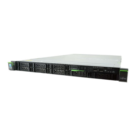
Fujitsu PRIMERGY RX200 S8 Manuals
Manuals and User Guides for Fujitsu PRIMERGY RX200 S8. We have
2
Fujitsu PRIMERGY RX200 S8 manuals available for free PDF download: Upgrade And Maintenance Manual, System Configurator And Order-Information Manual
Fujitsu PRIMERGY RX200 S8 Upgrade And Maintenance Manual (336 pages)
Brand:
Fujitsu
| Category:
Server
| Size: 11.8 MB
Table of Contents
Copyright and Trademarks
2
Version History
6
Table of Contents
7
1 Introduction
19
Notational Conventions
20
2 Before You Start
21
Classification of Procedures
23
Customer Replaceable Units (CRU)
23
Upgrade and Repair Units (URU)
24
Field Replaceable Units (FRU)
25
Average Task Duration
26
Tools You Need at Hand
27
Documents You Need at Hand
28
3 Important Information
31
Safety Instructions
31
CE Conformity
39
FCC Class a Compliance Statement
39
Environmental Protection
40
4 Basic Hardware Procedures
43
Using Diagnostics Information
43
Locating the Defective Server
43
Determining the Error Class
44
Global Error Indicator
44
Customer Self Service (CSS) Indicator
44
Locating the Defective Component
45
Local Diagnostic Indicators on the Front
45
Local Diagnostic Indicators on the System Board
45
Shutting down the Server
46
Disconnecting the Server from the Mains
47
Getting Access to the Component
47
Extending the Server out of the Rack
48
Removing the Server from the Rack
49
Removing the Fan Cover
51
Removing the Housing Cover
51
Reassembling
52
Installing the Housing Cover
52
Installing the Fan Cover
53
Mounting the Server in the Rack
54
Sliding the Server into the Rack
56
Connecting the Server to the Mains
57
Switching on the Server
58
Handling Riser Modules
58
Handling the Air Duct
62
5 Basic Software Procedures
63
Starting the Maintenance Task
63
Disabling Bitlocker Functionality
63
Disabling SVOM Boot Watchdog Functionality
64
Viewing Boot Watchdog Settings
64
Configuring Boot Watchdog Settings
65
Removing Backup and Optical Disk Media
66
Verifying and Configuring the Backup Software Solution
66
Note on Server Maintenance in a Multipath I/O Environment
67
Switching on the ID Indicator
69
Completing the Maintenance Task
70
Updating or Recovering the System Board BIOS and Irmc
70
Updating or Recovering the System Board BIOS
70
Updating or Recovering the Irmc
71
Verifying System Information Backup / Restore
73
Updating RAID Controller Firmware
73
Enabling Option ROM Scan
74
Verifying and Configuring the Backup Software Solution
75
Resetting the Boot Retry Counter
76
Viewing the Boot Retry Counter
76
Enabling SVOM Boot Watchdog Functionality
78
Enabling Replaced Components in the System BIOS
79
Verifying the Memory Mode
79
Verifying the System Time Settings
80
Viewing and Clearing the System Event Log (SEL)
81
Viewing the SEL
81
Clearing the SEL
82
Updating the NIC Configuration File in a Linux Environment
82
Enabling Bitlocker Functionality
83
Performing a RAID Array Rebuild
84
Looking up Changed MAC / WWN Addresses
85
Looking up MAC Addresses
85
Looking up WWN Addresses
86
Using the Chassis ID Prom Tool
87
Configuring LAN Teaming
88
After Replacing / Upgrading LAN Controllers
88
After Replacing the System Board
88
Switching off the ID Indicator
89
Performing a Fan Test after Replacing a Defective Fan
89
6 Power Supply
91
Basic Information
92
Installing a Power Supply Unit
93
Preliminary Steps
93
Removing the Dummy Cover
93
Installing the Power Supply Unit
94
Concluding Steps
95
Removing a Power Supply Unit
96
Preliminary Steps
98
Removing a Power Supply Unit
98
Installing the Dummy Cover
99
Concluding Steps
99
Replacing a Power Supply Unit
99
Preliminary Steps
100
Removing the Defective Power Supply Unit
100
Installing the New Power Supply Unit
101
Concluding Steps
101
Replacing the Power Distribution Board
101
Preliminary Steps
101
Removing the Defective Power Distribution Board
102
Installing the New Power Distribution Board
103
Concluding Steps
105
7 Hard Disk Drives / Solid State Drives
107
Basic Information
108
General Equipping Rules
108
Configuration with up to Four HDD/SSD Modules
109
Configuration with up to Eight HDD/SSD Modules
109
Installing a 2.5-Inch HDD/SSD Module
110
Preliminary Steps
110
Removing the 2.5-Inch Dummy Module
111
Installing the 2.5-Inch HDD/SSD Module
112
Concluding Steps
113
Removing a 2.5-Inch HDD/SSD Module
113
Preliminary Steps
113
Removing the 2.5-Inch HDD/SSD Module
114
Installing the 2.5-Inch Dummy Module
115
Concluding Steps
115
Replacing a 2.5-Inch HDD/SSD Module
115
Preliminary Steps
116
Removing the Defective 2.5-Inch HDD/SSD Module
116
Installing the New 2.5-Inch HDD/SSD Module
116
Concluding Steps
116
Replacing the 4Xhdd Backplane
117
Preliminary Steps
117
Removing the Defective 4Xhdd Backplane
117
Installing the New 4Xhdd Backplane
119
Concluding Steps
120
Replacing the 8Xhdd Backplane
120
Preliminary Steps
120
Removing the Defective 8Xhdd Backplane
121
Installing the New 8Xhdd Backplane
123
Concluding Steps
124
Converting to Configuration up to Eight HDD/SSD Modules
125
Preliminary Steps
125
Removing the 4Xhdd Backplane and the ODD Cage
125
Installing the 2Xhdd Cage and the 8Xhdd Backplane
127
Concluding Steps
129
8 Fans
131
Basic Information
132
Replacing a Fan Module
133
Preliminary Steps
133
Removing the Defective Fan Module
133
Installing the New Fan Module
134
Concluding Steps
134
9 Expansion Cards and Backup Units
135
Basic Information
136
Equipping the Pcie Slots
137
Handling Slot Brackets
140
Installing a Slot Bracket
140
Removing a Slot Bracket
145
Handling SFP+ Transceiver Modules
146
Installing SFP+ Transceiver Modules
146
Removing an SFP+ Transceiver Module
149
Expansion Cards and Riser Cards
152
Installing an Expansion Card - Slot 1-3
152
Preliminary Steps
152
Removing the Slot Cover - Slot 1-3
153
Installing the Expansion Card - Slot 1-3
154
Concluding Steps
156
Installing an Expansion Card - Slot 4
157
Preliminary Steps
157
Installing the Expansion Card - Slot 4
157
Concluding Steps
158
Removing an Expansion Card - Slot 1-3
159
Preliminary Steps
159
Removing the Expansion Card - Slot 1-3
159
Installing the Slot Cover - Slot 1-3
161
Concluding Steps
162
Removing an Expansion Card - Slot 4
162
Preliminary Steps
162
Removing the Expansion Card - Slot 4
162
Concluding Steps
163
Replacing an Expansion Card
164
Preliminary Steps
164
Removing the Defective Expansion Card
164
Installing the New Expansion Card
165
Concluding Steps
165
Replacing a Riser Card
166
Preliminary Steps
166
Removing the Defective Riser Card
166
Installing the New Riser Card
168
Concluding Steps
169
Replacing TFM
170
Preliminary Steps
170
Removing the Defective TFM
170
Installing the New TFM
171
Concluding Steps
171
Backup Units (BBU/FBU)
172
Basic Information
172
Installing a BBU
172
Preliminary Steps
172
Connecting the BBU Cable to the BBU
172
Installing the BBU in the Holder
173
Installing the BBU with the Holder
174
Concluding Steps
176
Installing an FBU
177
Preliminary Steps
177
Installing TFM to the RAID Controller (if Applicable)
178
Installing the FBU in the Holder
179
Connecting the FBU Cable to the FBU
180
Installing the FBU with the Holder
180
Concluding Steps
183
Removing a BBU
183
Preliminary Steps
183
Removing the BBU with the Holder
184
Removing the BBU from the Holder
186
Disconnecting the BBU Cable from the BBU
186
Concluding Steps
187
Removing an FBU
187
Preliminary Steps
187
Removing the FBU with the Holder
188
Disconnecting the FBU Cable from the FBU
189
Removing the FBU from the Holder
189
Concluding Steps
190
Replacing a BBU
190
Preliminary Steps
190
Removing the Defective BBU
190
Installing the New BBU
191
Concluding Steps
191
Replacing an FBU
192
Preliminary Steps
192
Removing the Defective FBU
192
Installing the New FBU
193
Concluding Steps
193
10 Main Memory
195
Basic Information
196
Memory Sequence
198
Population Rules
198
Independant Channel Mode
199
Mirrored Channel and Performance Modes
200
Rank Sparing Mode
201
Installing a Memory Module
205
Preliminary Steps
205
Selecting the Memory Slot
205
Installing a Memory Module
206
Concluding Steps
206
Removing a Memory Module
207
Preliminary Steps
207
Concluding Steps
208
Replacing a Memory Module
208
Preliminary Steps
208
Removing the Defective Memory Module
208
Installing the New Memory Module
209
Concluding Steps
209
11 Processors
211
Basic Information
212
Supported Processors
212
General Equipping Rules
212
Upgrading to Dual Processor Configuration
213
Preliminary Steps
213
Installing the Processor
214
Installing the Heat Sink
219
Upgrading the Main Memory
220
Installing Two Additional Fan Modules
221
Concluding Steps
221
Replacing a Processor
222
Preliminary Steps
222
Removing the Heat Sink
223
Removing the Defective Processor
224
Installing the New Processor
227
Applying the Thermal Paste to the Processor Surface
229
Installing the Heat Sink
231
Concluding Steps
232
Replacing a Heat Sink
232
Preliminary Steps
232
Removing the Defective Heat Sink
232
Installing the New Heat Sink
233
Concluding Steps
233
12 Optical Disk Drive
235
Basic Information
235
Installing the ODD
236
Preliminary Steps
236
Removing the Dummy Module
236
Installing the ODD
238
Concluding Steps
239
Removing the ODD
239
Preliminary Steps
239
Removing the ODD
240
Installing the Dummy Module
241
Concluding Steps
242
Replacing the ODD
242
Preliminary Steps
242
Removing the Defective ODD
242
Installing the New ODD
243
Concluding Steps
243
13 Front Panel and Front VGA/LAN Module
245
Basic Information
245
Installing the Front VGA And/Or Front LAN
246
Preliminary Steps
246
Removing the Front VGA/LAN Module
246
Removing the Covers
247
Installing the Front Connectors
247
Installing the Front VGA/LAN Module
250
Connecting the Front VGA Cable
251
Connecting the Front LAN Cable
251
Concluding Steps
252
Using the Front Management LAN Connector
253
Removing the Front VGA And/Or Front LAN
254
Preliminary Steps
254
Disconnecting the Front LAN Cable
254
Disconnecting the Front VGA Cable
255
Removing the Front VGA/LAN Module
256
Removing the Front Connectors
256
Installing the Front VGA/LAN Module
259
Concluding Steps
259
Replacing the Front VGA And/Or Front LAN Cable
260
Preliminary Steps
260
Removing the Defective Front VGA And/Or Front LAN Cable
260
Installing the New Front VGA And/Or Front LAN Cable
261
Concluding Steps
261
Replacing the Front LAN Card
261
Preliminary Steps
261
Removing the Defective Front LAN Card
262
Installing the New Front LAN Card
262
Concluding Steps
262
Replacing the Front Panel Board
263
Preliminary Steps
263
Removing the Defective Front Panel Board
264
Installing the New Front Panel Module
268
Concluding Steps
272
14 Serial Interface
273
Basic Information
273
Installing the Serial Interface
273
Preliminary Steps
274
Removing the Slot Cover
274
Installing the Serial Interface
274
Concluding Steps
275
Removing the Serial Interface
276
Preliminary Steps
276
Installing the Slot Cover
277
Concluding Steps
277
Replacing the Serial Interface
278
Preliminary Steps
278
Removing the Defective Serial Interface
278
Installing the New Serial Interface
278
Concluding Steps
278
15 System Board and Components
279
Basic Information
279
Replacing the CMOS Battery
280
Preliminary Steps
280
Replacing the Defective CMOS Battery
281
Concluding Steps
281
USB Flash Module (UFM)
282
Installing the UFM
282
Preliminary Steps
282
Concluding Steps
283
Software Configuration
284
Removing the UFM
284
Preliminary Steps
284
Removing the UFM
285
Concluding Steps
286
Replacing the UFM
287
Preliminary Steps
287
Removing the Defective UFM
287
Installing the New UFM
288
Concluding Steps
288
Software Configuration
289
Trusted Platform Module (TPM)
289
Installing the TPM
289
Preliminary Steps
289
Installing the TPM
290
Concluding Steps
292
Removing the TPM
293
Preliminary Steps
293
Removing the TPM
295
Concluding Steps
296
Replacing the TPM
297
Preliminary Steps
297
Removing the Defective TPM
298
Installing the New TPM
298
Concluding Steps
298
Onboard SAS Enabling Key
299
Installing the Onboard SAS Enabling Key
299
Preliminary Steps
299
Concluding Steps
300
Removing the Onboard SAS Enabling Key
301
Preliminary Steps
301
Concluding Steps
301
Replacing the Onboard SAS Enabling Key
302
Preliminary Steps
302
Concluding Steps
302
Replacing the System Board
303
Preliminary Steps
305
Removing the Defective System Board
306
Installing the New System Board
309
Concluding Steps
311
16 Cables
313
Overview Cables
313
Cabling
314
17 Appendix
321
Mechanical Overview
321
Server Front
321
Server Rear
322
Server Interior
323
Connectors and Indicators
325
Connectors and Indicators on the System Board
325
Onboard Connectors
325
Onboard Indicators and Controls
327
I/O Panel Connectors
329
I/O Panel Indicators
330
Indicators on Power Supply Units
331
Indicators on the Front Panel
332
Onboard Settings
334
Minimum Startup Configuration
335
Advertisement
Fujitsu PRIMERGY RX200 S8 System Configurator And Order-Information Manual (28 pages)
System configurator and order-information guide
Brand:
Fujitsu
| Category:
Server
| Size: 0.59 MB
Table of Contents
Table of Contents
1
Memory
2
Accessible Drives
3
Fibre-Channel Controller
3
Communication/Network
3
Independent Channel Mode
14
Mirrored Channel Mode
14
Performance Channel Mode
14
Rank Sparing Mode
15
System Management Products (Remoteview)
25
Miscellaneous
25
Country Specific Power Cord
26
Change Report
28
Advertisement
Related Products
Fujitsu PRIMERGY RX200 S5
Fujitsu PRIMERGY RX200 S2
Fujitsu PRIMERGY RX200 S6
Fujitsu PRIMERGY RX200 S7
Fujitsu Primergy RX200 S4
Fujitsu PRIMERGY RX200 S3
Fujitsu PRIMERGY RX220
Fujitsu PRIMERGY RX2520 M1
Fujitsu PRIMERGY RX2530 M1
Fujitsu PRIMERGY RX2510 M2
Fujitsu Categories
Air Conditioner
Laptop
Server
Scanner
Storage
More Fujitsu Manuals
Login
Sign In
OR
Sign in with Facebook
Sign in with Google
Upload manual
Upload from disk
Upload from URL