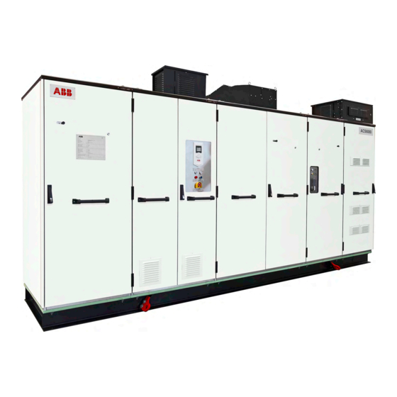
Sign In
Upload
Manuals
Brands
ABB Manuals
DC Drives
ACS6080
ABB ACS6080 Manuals
Manuals and User Guides for ABB ACS6080. We have
4
ABB ACS6080 manuals available for free PDF download: User Manual
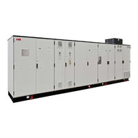
ABB ACS6080 User Manual (266 pages)
SYSTEM DRIVES
Brand:
ABB
| Category:
DC Drives
| Size: 17.56 MB
Table of Contents
Table of Contents
3
1 About this Manual
19
Equipment Covered by this Manual
19
Structure of the User Documentation
19
Terms and Abbreviations
20
Table 1-1 Terms and Abbreviations
20
Related Documents
26
Table 1-2 Maintenance
26
Table 1-3 Technical Data
26
Table 1-4 Schematics
26
Table 1-5 Specifications and Guidelines
26
Target Groups and Required Qualification
27
Handling
27
Table 1-6 Service
27
Table 1-7 Communication Interfaces
27
Table 1-8 User Manuals Related to Drive Units
27
Mechanical Installation
28
Electrical Installation
28
Operation
28
Maintenance
28
User's Responsibilities
28
Intended Use of Equipment
28
Quality Certificates and Applicable Standards
29
Table 1-9 Standards that Are Referred to in this Document
29
Identifying the Delivery
30
Tools
30
2 Important Safety Information
31
Safety Standards
31
Safety Messages
31
Product Safety Labels
32
Figure 2-1 Product Warning Label Examples (Label Placement Depends on the Drive)
32
General Safety Instructions
33
The 7 Steps that Save Lives
34
Possible Residual Risks
36
Important Note - Main Circuit Breaker
37
Figure 2-2 Drive System Overview
37
Safety and Protection Requirements
38
Safety and Protection Requirements for the MCB
38
Maintenance Recommendation
39
Figure 2-3 MCB Opening Timing Diagram
39
3 Power Electronics and Cabinet Features
41
Drive System Topology
41
Drive
41
Figure 3-1 Common DC-Bus Principle for Single Motor Drive (A) and Multi-Motor Drive (B)
41
Figure 3-2 ACS6000 Drive Example
42
ACS6000 Cabinet Units
43
Final Drive Configuration
43
Motor
43
Standard Cabinet Units
44
Active Rectifier Unit (Aru)/Inverter Unit (INU)
44
Figure 3-3 ARU/INU Block Diagram
44
Figure 3-4 ARU/INU Circuit Diagram
44
Figure 3-5 ARU/INU (A) and Phase Modules with Igcts (B)
45
Table 3-1 Main Components in an ARU/INU Cabinet
45
Line Supply Unit (LSU)
46
Figure 3-6 LSU Block Diagram
46
Figure 3-7 LSU (12-Pulse) Circuit Diagram
46
Figure 3-8 LSU (12-Pulse)
47
Table 3-2 Main Components in a 12-Pulse LSU Cabinet
47
Capacitor Bank Unit (CBU)
48
Figure 3-9 CBU
48
Table 3-3 Main Components in a CBU Cabinet
48
Terminal Unit (TEU)
49
Figure 3-10 TEU (1000 MM)
49
Control Unit (COU)
50
COU Versions
50
Figure 3-11 Control Units: 1000 MM COU (A) and 600 MM COU (B)
51
Control System Configuration
52
Figure 3-12 Block Diagram of Control System
52
AMC Circuit Board
53
Figure 3-13 Examples of AMC Circuit Boards in 1000 MM COU (A) and 600 MM COU (B)
53
Main Circuit Breaker
54
Figure 3-14 AMC Circuit Board Example
54
Speed and Torque Control
55
Figure 3-15 DTC Control Platform
55
Peripheral I/O Devices
56
Local Control Panels
56
Figure 3-16 Local Control Panels on 1000 MM COU (A) and 600 MM COU (B)
56
S800 I/O System
57
Figure 3-17 Typical S800 I/O Station
57
Water Cooling Unit (WCU)
58
Table 3-4 Main Components in a WCU Cabinet
58
Figure 3-18 WCU1400 (A) and WCU800 (B) Cabinet and System Components
59
Cooling Circuit
60
External Cooling Connection
60
Figure 3-19 Cooling Circuit in an ACS6000 Drive
60
Optional Cabinet Units
61
Input Reactor Unit (IRU)
61
Figure 3-20 IRU Cabinet (A) and Circuit Diagram (B)
61
Input Filter Unit (IFU)
62
Figure 3-21 IFU Cabinet (A) and Circuit Diagram (B)
62
Voltage Limiter Unit (VLU)
63
Figure 3-22 VLU Cabinet (A) and Circuit Diagram (B)
63
Braking Units
64
Table 3-5 BCU Braking Power
64
Table 3-6 RBU Braking Power
64
Braking Chopper Unit
65
Figure 3-23 BCU Cabinet (A) and Circuit Diagram (B)
65
Figure 3-24 RBU Cabinet (A) and Circuit Diagram (B)
66
Resistor Braking Unit
66
Excitation Unit (EXU)
67
Figure 3-25 EXU D4 Frame Cabinet (A) and EXU D5 Frame Cabinet (B)
67
DCS800 Control Panel
68
Output Disconnector
68
Reversing Switch
68
Customer Interface Unit (CIU)
69
Figure 3-26 CIU Cabinet (A) and WCU800 Cabinet (B)
69
Arc Detection with Arc Guard (Optional)
70
Air Cooling
70
Air-To-Air Heat Exchangers
70
Figure 3-27 ACS6000 Example Drive with Air-To-Air Heat Exchanger
70
Auxiliary Fan Units
71
Figure 3-28 Auxiliary Fan Unit
71
Figure 3-29 Air Circulation through Ventilation Grids in 600 MM COU (A), 1000 MM COU (B) and WCU800 (C)
71
Cabinet Design
72
Figure 3-30 Basic Cabinet Design
72
Door Locking System
73
Arc Resistant Design
74
Internal Arc Classification
74
Figure 3-31 IAC Label Example
74
Table 3-7 ABB Arc Resistant Classes
74
Busbars and Grounding
75
AC Busbars
75
DC Busbars
75
PE Busbar
75
PG Busbar
75
Figure 3-32 Busbars
75
4 Transportation, Storage and Disposal
77
Safety
77
Transport Conditions
77
Unpacking and Inspection
77
Identifying Transport Units
77
Lifting and Transportation
79
Lifting Recommendations
80
Figure 4-1 Lifting Bracket on Base Frame of a Drive, Safety Hook
80
Figure 4-2 Lift Frame (A) and Lift Spreader (B)
81
Storage
82
Storing and Handling of Spare Parts
82
Warranty Information
83
Disposing Package Materials and Components
84
5 Mechanical Installation
85
Safety
85
Overview
85
General Notes on Installation
86
Dimensions and Clearances
86
Access to the Cabinets
86
Cabinet Roof
86
Fire Protection
86
Cable Duct Material
87
Installation Material
87
Tools
87
Floor Preparation
87
Floor Fixation
87
Raw Water Circuit
87
Aligning Transport Units
88
Joining Transport Units
90
Figure 5-1 Connection Point Locations on Transport Units
90
Joining Water Pipes
91
Figure 5-2 Minimum Distances and Locking Bolt Orientation (a = Front)
91
Removing a Pipe Joint
92
Joining Busbars
93
Figure 5-3 Bolted Busbar Connection
93
Joining the Busbars
93
DC Busbars
94
Figure 5-4 Top View of DC Busbar Configuration 1
94
Figure 5-5 Top View DC Busbar Configurations 2 (A), 3 (B) and 4 (C)
95
Figure 5-6 Ground Busbar Joints
96
Ground Busbars
96
AC Busbars between COU/TEU and LSU (5/7/9 MVA)
97
Figure 5-7 AC Busbar Joints between the COU/TEU and LSU (5/7/9 MVA)
97
AC Busbars between COU/TEU and LSU (14 MVA)
98
Figure 5-8 AC Busbar Joints between the COU/TEU and LSU (14 MVA)
98
AC Busbar Joints - Without Disconnector
99
AC Busbars between COU/TEU and ARU/INU
99
Table 5-1 Installation Material for AC Busbars (COU/TEU - ARU/INU)
99
AC Busbar Joints - with Motorized Disconnector
100
Installing and Removing Air-To-Air Heat Exchangers
102
Installing Air-To-Air Heat Exchangers
102
Figure 5-10 Tools for Installing an Air-To-Air Heat Exchanger
102
Figure 5-9 Air-To-Air Heat Exchanger (Type LT-5-5165-UL)
102
Installation
103
Figure 5-11 Correct and Incorrect Cable Installation
104
Figure 5-12 ARU/INU/IFU Cable Routing
106
Figure 5-13 LSU Cable Routing
106
Removing Air-To-Air Heat Exchangers
107
Figure 5-14 Air-To-Air Heat Exchangers (Type LT-5-5165-UL)
107
Figure 5-15 Tools for Removing an Air-To-Air Heat Exchanger
108
Removing an Air-To-Air Heat Exchanger
108
Reinstalling an Air-To-Air Heat Exchanger
109
Installing the Transformers of Air-To-Air Heat Exchangers
110
Figure 5-16 Installation Example of Transformers in an Air-To-Air Heat Exchanger
110
Installing the Pressure Relief Vents
111
Figure 5-17 Connect Wires to Terminal Block
111
Figure 5-18 Pressure Relief Vents
111
Figure 5-19 Tools Required to Fasten the Pressure Relief Vent to the Roof
112
Figure 5-20 Installation Example of Pressure Relief Vents
112
Attaching the Sealing Tapes
113
Figure 5-21 Attach Sealing Tape to the Joining Crossbar (1)
113
Installing the Roof Joints and the Roof Attachments
114
Installing Roof Joints
114
Figure 5-22 Roof Joints (1)
114
Table 5-2 Installation Material for Roof Joints
114
Installing Roof Attachments
115
Figure 5-23 Roof Attachment Parts
115
Figure 5-24 Recommended Ceiling and Wall Fixings
116
6 Electrical Installation
117
Safety
117
Figure 6-1 Phase Module on Lift Table
117
Cable Requirements
118
Power Cables
118
Auxiliary and Control Cables
118
Synchronization Cables
118
Grounding the Drive System
119
Grounding Diagrams
119
Figure 6-2 Grounding the Input Side (A) and Output Side (B) of the Drive System
119
Ground Cable Connection
120
Cable Shield Ground Connection
120
Figure 6-3 System Ground Connection (1) in a 600 MM TEU
120
EXU Cabinet Ground Connections
121
Internal Wiring
121
Figure 6-4 Grounding the EXU
121
Optical Fiber Cables
122
Installing the Standard Optical Fibers
122
Figure 6-5 Cable Tray and Cable Ducts in an LSU (a = Front)
122
Optical Fiber Cables for the Optional Arc Guard System
123
Figure 6-6 Arc Guard System™ in an Optional Roof Extension Box (REB)
123
Connecting the Detector Cables to the Arc Monitor Device
124
Figure 6-7 Location of Arc Guard Sensors in a TEU
124
Figure 6-8 Cable Tray and Cable Ducts in an LSU (a = Front)
124
Cable Entry Systems
125
Frames with Type 1 Sealing Modules
125
Figure 6-9 Cable Entry with Type 1 Sealing Modules
125
Figure 6-10 Cable Entry Frame with Type 1 Sealing Modules
126
Table 6-1 Cable Entry Frames for Type 1 Sealing Modules
126
Frame with Type 2 Sealing Modules
127
Plates with Cable Glands
127
Figure 6-11 Cable Entry with Type 2 Sealing Modules
127
Figure 6-12 Cable Gland
127
EMC Plates with Sealing Grommets
128
Preparing Cable Entry Systems for TEU, ARU and EXU Cabinets
128
TEU Cable Entry Frames with Type 1 Sealing Modules
128
Figure 6-13 Cable Entry with EMC Plates
128
Figure 6-14 TEU 1000 MM Cabinet (a = Back) with Top (1) and Bottom (2
129
ARU Cable Entry Frames with Type 1 Sealing Modules
130
Figure 6-15 Short Busbar Removal in ARU
130
EXU Cable Entry with EMC Plate and Sealing Grommets
131
Figure 6-16 EXU with Top Cable Entry (A) and EXU with Bottom Cable Entry (B)
131
Figure 6-17 EXU Cabinet
131
Power, Ground and Equipotential Bonding Conductor Cables
132
Determining the Cable Length
132
Preparing Cables for Sealing Modules
133
Figure 6-18 Preparing Power Cables for Sealing Modules
133
Preparing Cables for Cable Glands
134
Preparing Cables for EMC Plates
134
Figure 6-19 Prepare Power Cables for Cable Glands
134
Figure 6-20 Preparing Cables for EMC Plates: (A) Cables with an Outer Screen or Shield, (B) Cables Without an Outer Screen or Shield or (C) Cables in an EXU Cabinet
135
Connecting the Cables
136
Checking the Cable Insulation
136
EXU Cabinet Connections
136
Figure 6-21 Cable Connections in an EXU Cabinet
136
Bolted Busbar Connections - Marine Drives
137
Figure 6-22 Minimum Distance between Bolted Joints of Different Phases in an EXU
137
Figure 6-23 Bolted Busbar Connection - Marine Drives
137
Bolted Busbar Connections - Non-Marine Drives
138
Figure 6-24 Bolted Busbar Connection - Non-Marine Drive
138
Auxiliary Power, Control and Serial Communication Cables
139
Determining the Cable Length
139
Preparing Cables for Sealing Modules
140
Figure 6-25 Cable Entry with Sealing Modules
140
Figure 6-26 Preparing Control Cables for Sealing Modules
140
Preparing Cables for Cable Glands
141
Preparing Cables for EMC Plates
141
Figure 6-27 Preparing Auxiliary Control Cables for Cable Glands
141
Figure 6-28 Preparing the Screens of Control Cables for EMC Plates
142
Routing Cables in a WCU
143
Routing Cables in a COU Cabinet
143
Figure 6-29 Preparing Control Cables for EMC Plates
143
Figure 6-30 Top Cable Entry of 600 MM COU
144
Figure 6-31 Cable Route in COU (600 MM) Top Cable Entry
144
Top Cable Entry
144
Bottom Cable Entry
145
Figure 6-32 Cable Route in COU (1000 MM) Top Cable Entry
145
Figure 6-33 Cable Route in COU (600 MM) Bottom Cable Entry
145
Connecting the Cables
146
Figure 6-34 Cable Route in COU (1000 MM) Bottom Cable Entry
146
Routing Cables in an EXU Cabinet
147
Auxiliary Power and Control Cables
147
Figure 6-35 Shield Grounding Point for Encoder Cable on NTAC Pulse Encoder (A) and Synchronous Serial Interface (B)
147
Optical Fiber Cables
148
Figure 6-36 Cable Routing Examples in an EXU Cabinet with an ED5V
148
Routing Optical Fiber Cables in an EXU Cabinet with an ED5V, EB5R, EB5S, EB7P or EB7Q Type DCS800 Converter
149
Figure 6-37 DCS800 Converter (ED5V, EB5R, EB5S, EB7P and EB7Q Types)
149
Figure 6-38 COM-8X Circuit Board (A) in a DCS800 Converter (ED5V, EB5R and EB5S Types) and a Detail of Channel CH0 (B) on the Board
149
Figure 6-39 Cable Routing Example in an EXU Cabinet with an ED5V, EB5R, EB5S, EB7P or EB7Q Type DCS800 Converter
150
Routing Cables in an EXU Cabinet with an ED7Y Type DCS800 Converter
151
Figure 6-40 DCS800 Converter (ED7Y)
151
Figure 6-41 COM-8X Circuit Board (A) in a DCS800 Converter (ED7Y Type) and a Detail of Channel CH0 (B) on the Board
151
Figure 6-42 Cable Routing Example in an EXU Cabinet with an ED5V, EB5R or EB5S Type DCS800 Converter
152
Routing Azipod® Encoder Cables
153
Handling and Installation
153
Routing Cables through the REB (WCU)
154
Figure 6-43 REB Cable Entry
154
Heating Cable
155
Figure 6-44 Heating Cable Connection
155
Final Checks
156
Advertisement
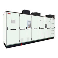
ABB ACS6080 User Manual (220 pages)
Brand:
ABB
| Category:
DC Drives
| Size: 15.62 MB
Table of Contents
Table of Contents
3
About this Manual
17
Product Overview
17
Standard Applications
17
Equipment Covered by this Manual
18
Structure of the User Documentation
18
Terms and Abbreviations
19
Table 1-1 Terms and Abbreviations
19
Related Documents
24
Table 1-2 Maintenance
24
Table 1-3 Technical Data
24
Table 1-4 Schematics
24
Table 1-5 Specifications and Guidelines
24
Table 1-6 Service
25
Table 1-7 Communication Interfaces
25
Table 1-8 User Manuals Related to Drive Units
25
Target Groups and Required Qualification
26
Handling
26
Mechanical Installation
26
Electrical Installation
26
Operation
26
Maintenance
26
User's Responsibilities
27
Intended Use of Equipment
27
Quality Certificates and Applicable Standards
27
Table 1-9 Standards that Are Referred to in this Document
27
Identifying the Delivery
28
Tools
28
Important Safety Information
29
Safety Standards
29
Safety Messages
29
Product Safety Labels
30
Figure 2-1 Product Warning Label Examples (Label Placement Depends on the Drive)
30
General Safety Instructions
31
The 7 Steps that Save Lives
32
Possible Residual Risks
34
Important Note - Main Circuit Breaker
35
Figure 2-2 Drive System Overview
35
Safety and Protection Requirements
36
Safety and Protection Requirements for the MCB
36
Maintenance Recommendation
37
Figure 2-3 MCB Opening Timing Diagram
37
Power Electronics and Cabinet Features
39
Drive System Topology
39
Drive
39
Figure 3-1 Common DC-Bus Principle for Single Motor Drive (A) and Multi-Motor Drive (B)
39
Figure 3-2 ACS6080 Drive Example
40
ACS6080 Cabinet Units
41
Final Drive Configuration
41
Motor
41
Standard Cabinet Units
42
Active Rectifier Unit (Aru)/Inverter Unit (INU)
42
Figure 3-3 ARU/INU Block Diagram
42
Figure 3-4 ARU/INU Circuit Diagram
42
Figure 3-5 ARU/INU (A) and Phase Modules with Igcts (B)
43
Table 3-1 Main Components in an ARU/INU Cabinet
43
Line Supply Unit (LSU)
44
Figure 3-6 LSU Block Diagram
44
Figure 3-7 LSU (12-Pulse) Circuit Diagram
44
Figure 3-8 LSU (12-Pulse)
45
Table 3-2 Main Components in a 12-Pulse LSU Cabinet
45
Capacitor Bank Unit (CBU)
46
Figure 3-9 CBU
46
Table 3-3 Main Components in a CBU Cabinet
46
Terminal Unit (TEU)
47
Figure 3-10 TEU (1000 MM)
47
Control Unit (COU)
48
Figure 3-11 Master COU (1000 MM) and Control Equipment
48
Main Circuit Breaker
49
Peripheral I/O Devices
49
S500 I/O System
49
Speed and Torque Control
49
Figure 3-12 Control Panel
50
Figure 3-13 Location of Control Panels on Master COU (A) and Slave COU (B)
50
Local Control Panels
50
Water Cooling Unit (WCU)
51
Table 3-4 Main Components in a WCU Cabinet
51
Figure 3-14 WCU1400 (A) and WCU800 (B) Cabinet and System Components
52
Cooling Circuit
53
External Cooling Connection
53
Figure 3-15 Cooling Circuit in an ACS6080 Drive
53
Optional Cabinet Units
54
Input Reactor Unit (IRU)
54
Figure 3-16 IRU Cabinet (A) and Circuit Diagram (B)
54
Input Filter Unit (IFU)
55
Figure 3-17 IFU Cabinet (A) and Circuit Diagram (B)
55
Voltage Limiter Unit (VLU)
56
Figure 3-18 VLU Cabinet (A) and Circuit Diagram (B)
56
Braking Units
57
Table 3-5 BCU Braking Power
57
Table 3-6 RBU Braking Power
57
Braking Chopper Unit
58
Figure 3-19 BCU Cabinet (A) and Circuit Diagram (B)
58
Figure 3-20 RBU Cabinet (A) and Circuit Diagram (B)
59
Resistor Braking Unit
59
Excitation Unit (EXU)
60
Figure 3-21 EXU H4/T4 Frame Cabinet (A) and EXU H6 Frame Cabinet (B)
60
DCS880/DCT880 Control Panel
61
Output Disconnector
61
Customer Interface Unit (CIU)
62
Figure 3-22 CIU Cabinet (A) and WCU800 Cabinet (B)
62
Arc Detection with Arc Guard (Optional)
63
Air Cooling
63
Air-To-Air Heat Exchangers
63
Figure 3-23 ACS6080 Example Drive with Air-To-Air Heat Exchanger
63
Auxiliary Fan Units
64
Figure 3-24 Auxiliary Fan Unit
64
Figure 3-25 Air Circulation through Ventilation Grids in 600 MM COU (A), 1000 MM COU (B) and WCU800 (C)
64
Cabinet Design
65
Figure 3-26 Basic Cabinet Design
65
Door Locking System
66
Arc Resistant Design
67
Internal Arc Classification
67
Figure 3-27 IAC Label Example
67
Table 3-7 ABB Arc Resistant Classes
67
Busbars and Grounding
68
AC Busbars
68
DC Busbars
68
PE Busbar
68
PG Busbar
68
Figure 3-28 Busbars
68
Transportation, Storage and Disposal
69
Safety
69
Transport Conditions
69
Unpacking and Inspection
69
Identifying Transport Units
69
Lifting and Transportation
71
Lifting Recommendations
72
Figure 4-1 Lifting Bracket on Base Frame of a Drive, Safety Hook Secured to Lifting Bracket and Eye Bolt
72
Figure 4-2 Lift Frame (A) and Lift Spreader (B)
73
Storage
74
Storing and Handling of Spare Parts
75
Warranty Information
75
Disposing Package Materials and Components
76
Mechanical Installation
77
Safety
77
Overview
77
General Notes on Installation
78
Dimensions and Clearances
78
Access to the Cabinets
78
Cabinet Roof
78
Fire Protection
78
Cable Duct Material
79
Installation Material
79
Tools
79
Floor Preparation
79
Floor Fixation
79
Raw Water Circuit
79
Aligning Transport Units
80
Joining Transport Units
82
Figure 5-1 Connection Point Locations on Transport Units
82
Joining Water Pipes
83
Figure 5-2 Minimum Distances and Locking Bolt Orientation (a = Front)
83
Removing a Pipe Joint
84
Joining Busbars
85
Figure 5-3 Bolted Busbar Connection
85
Joining the Busbars
85
DC Busbars
86
Figure 5-4 Top View of DC Busbar Configuration 1
86
Figure 5-5 Top View DC Busbar Configurations 2 (A), 3 (B) and 4 (C)
87
Figure 5-6 Ground Busbar Joints
88
Ground Busbars
88
AC Busbars between COU/TEU and LSU (5/7/9 MVA)
89
Figure 5-7 AC Busbar Joints between the COU/TEU and LSU (5/7/9 MVA)
89
AC Busbars between COU/TEU and LSU (14 MVA)
90
Figure 5-8 AC Busbar Joints between the COU/TEU and LSU (14 MVA)
90
AC Busbar Joints - Without Disconnector
91
AC Busbars between COU/TEU and ARU/INU
91
Table 5-1 Installation Material for AC Busbars (COU/TEU - ARU/INU)
91
AC Busbar Joints - with Motorized Disconnector
92
Installing and Removing Air-To-Air Heat Exchangers
94
Installing Air-To-Air Heat Exchangers
94
Figure 5-10 Tools for Installing an Air-To-Air Heat Exchanger
94
Figure 5-9 Air-To-Air Heat Exchanger (Type LT-5-5165-UL)
94
Installation
95
Figure 5-11 Correct and Incorrect Cable Installation
96
Figure 5-12 ARU/INU/IFU Cable Routing
98
Figure 5-13 LSU Cable Routing
98
Removing Air-To-Air Heat Exchangers
99
Figure 5-14 Air-To-Air Heat Exchangers (Type LT-5-5165-UL)
99
Figure 5-15 Tools for Removing an Air-To-Air Heat Exchanger
100
Removing an Air-To-Air Heat Exchanger
100
Reinstalling an Air-To-Air Heat Exchanger
101
Installing the Transformers of Air-To-Air Heat Exchangers
102
Figure 5-16 Installation Example of Transformers in an Air-To-Air Heat Exchanger
102
Installing the Pressure Relief Vents
103
Figure 5-17 Connect Wires to Terminal Block
103
Figure 5-18 Pressure Relief Vents
103
Figure 5-19 Tools Required to Fasten the Pressure Relief Vent to the
104
Figure 5-20 Installation Example of Pressure Relief Vents
104
Attaching the Sealing Tapes
105
Figure 5-21 Attach Sealing Tape to the Joining Crossbar (1)
105
Installing the Roof Joints and the Roof Attachments
106
Installing Roof Joints
106
Figure 5-22 Roof Joints (1)
106
Table 5-2 Installation Material for Roof Joints
106
Installing Roof Attachments
107
Figure 5-23 Roof Attachment Parts
107
Figure 5-24 Recommended Ceiling and Wall Fixings
108
ABB ACS6080 User Manual (211 pages)
Brand:
ABB
| Category:
Industrial Equipment
| Size: 13.08 MB
Table of Contents
Table of Contents
3
About this Manual
14
Product Overview
14
Standard Applications
14
Equipment Covered by this Manual
14
Structure of the User Documentation
15
Terms and Abbreviations
15
Related Documents
19
Maintenance
19
Technical Data
20
Schematics
20
Specifications and Guidelines
20
Service
20
Communication Interfaces
21
User Manuals Related to Drive Units
21
Target Groups and Required Qualification
21
Handling
21
Mechanical Installation
21
Electrical Installation
22
Operation
22
Maintenance
22
User's Responsibilities
22
Intended Use of Equipment
22
Quality Certificates and Applicable Standards
23
Standards
23
Identifying the Delivery
23
Tools
24
Document Conventions
24
Important Safety Information
25
Safety Messages and Safety Signs in this Document
25
Safety Messages
25
Safety Signs
25
Product Safety Labels
26
Electrical Safety
26
General Safety Instructions
26
Fig. 1. Product Warning Label Examples (Label Placement Depends on the Drive)
26
The 7 Steps that Save Lives
27
Possible Residual Risks
29
Main Circuit Breaker Protection Device
30
Fig. 2. Drive System Overview
30
Safety and Protection Requirements
31
Safety and Protection Requirements for the MCB
31
Fig. 3. MCB Opening Timing Diagram
31
Maintenance Recommendation
32
Power Electronics and Cabinet Features
33
Drive System Topology
33
Drive
33
Fig. 4. Common DC-Bus Principle for (A) Single Motor Drive and (B) Multi-Motor Drive
33
Fig. 5. ACS6080 Drive Example
34
ACS6080 Cabinet Units
35
Final Drive Configuration
35
Motor
35
Standard Cabinet Units
36
Active Rectifier Unit (Aru)/Inverter Unit (INU)
36
Fig. 6. ARU/INU Block Diagram
36
Fig. 7. ARU/INU Circuit Diagram
36
Fig. 8. (A) ARU/INU and (B) Phase Module with Igcts
37
Table 1 Main Components in an ARU/INU Cabinet
37
Line Supply Unit (LSU)
38
Fig. 9. LSU Block Diagram
38
Fig. 10. LSU (12-Pulse) Circuit Diagram
38
Fig. 11. LSU (12-Pulse)
39
Table 2 Main Components in a 12-Pulse LSU Cabinet
39
Capacitor Bank Unit (CBU)
40
Fig. 12. CBU
40
Table 3 Main Components in a CBU Cabinet
40
Terminal Unit (TEU)
41
Fig. 13. TEU (1000 MM)
41
Control Unit (COU)
42
Fig. 14. Master COU (1000 MM) and Control Equipment
42
Main Circuit Breaker
43
Speed and Torque Control
43
Peripheral I/O Devices
43
Local Control Panels
44
Fig. 15. Location of (1) Control Panels on Master (A) COU and (B)
44
Water Cooling Unit (WCU)
45
Table 4 Main Components in a WCU Cabinet
45
Fig. 16. (A) WCU1400 and (B) WCU800 Cabinet and System Components
46
Cooling Circuit
47
External Cooling Connection
47
Fig. 17. Cooling Circuit in an ACS6080 Drive
47
Optional Cabinet Units
48
Input Reactor Unit (IRU)
48
Fig. 18. (A) IRU Cabinet and (B) Circuit Diagram
48
Input Filter Unit (IFU)
49
Fig. 19. (A) IFU Cabinet and (B) Circuit Diagram
49
Voltage Limiter Unit (VLU)
50
Fig. 20. (A) VLU Cabinet and (B) Circuit Diagram
50
Braking Units
51
Table 5 BCU Braking Power
51
Table 6 RBU Braking Power
51
Braking Chopper Unit
52
Fig. 21. (A) BCU Cabinet and (B) Circuit Diagram
52
Resistor Braking Unit
53
Fig. 22. (A) RBU Cabinet and (B) Circuit Diagram
53
Excitation Unit (EXU)
54
Fig. 23. (A) EXU H4/T4 Frame Cabinet and (B) EXU H6 Frame Cabinet
54
DCS880/DCT880 Control Panel
55
Output Disconnector
55
Customer Interface Unit (CIU)
56
Fig. 24. (A) CIU Cabinet and (B) WCU800 Cabinet
56
Arc Detection with Arc Guard (Optional)
57
Air Cooling
57
Air-To-Air Heat Exchangers
57
Fig. 25. ACS6080 Example Drive with Air-To-Air Heat Exchanger
57
Auxiliary Fan Units
58
Fig. 26. Auxiliary Fan Unit
58
Fig. 27. Air Circulation through Ventilation Grids in (A) 600 MM COU, (B) 1000 MM COU, and (C) WCU800
58
Cabinet Design
59
Fig. 28. Basic Cabinet Design
59
Door Locking System
60
Arc Resistant Design
60
Internal Arc Classification
60
Fig. 29. IAC Label Example
60
Table 7 ABB Arc Resistant Classes
60
Busbars and Grounding
61
AC Busbars
61
DC Busbars
61
PE Busbar
61
PG Busbar
61
Fig. 30. Busbars
61
Transportation, Storage, and Disposal
62
Safety
62
Transport Conditions
62
Unpacking and Inspection
62
Identifying Transport Units
62
Packing List
62
Packing Label
63
Lifting and Transportation
64
Lifting Attachment Types
65
Fig. 31. Lifting Attachment Types
65
Lifting with Lifting Plates
66
Lifting with Rotating Eyebolts
67
Reinstalling Lifting Attachments
68
Fig. 32. Torque Wrench Socket for Rotating Eyebolt (Not Included in Delivery)
68
Table 8 Lifting Attachment Specifications
68
Sling Configurations for Lift Frames and Spreader Frames
69
Fig. 33. (A) Lift Frame and (B) Lift Spreader
69
Storage
70
Storage Conditions
70
Storing the Drive
70
Storage and Handling of Spare Parts
71
Warranty Information
71
Disposing Package Materials and Components
71
Mechanical Installation
72
Safety
72
Overview
72
General Notes on Installation
72
Dimensions and Clearances
72
Access to the Cabinets
72
Cabinet Roof
73
Fire Protection
73
Cable Duct Material
73
Installation Material
73
Tools
73
Floor Preparation
73
Floor Fixation
73
Raw Water Circuit
73
Aligning Transport Units
74
Joining Transport Units
76
Fig. 34. Connection Point Locations on Transport Units
76
Joining Water Pipes
77
Fig. 35. Minimum Distances and Locking Bolt Orientation (a = Front)
78
Removing a Pipe Joint
79
Joining Busbars
79
Fig. 36. Bolted Busbar Connection
79
DC Busbars
80
Fig. 37. Top View of DC Busbar Configuration 1
80
Fig. 38. Top View (A) DC Busbar Configuration 2, (B) Configuration 3, and
81
Ground Busbars
82
Fig. 39. Ground Busbar Joints
82
AC Busbars between COU/TEU and LSU (5/7/9 MVA)
83
Fig. 40. AC Busbar Joints between the COU/TEU and LSU (5/7/9 MVA)
83
AC Busbars between COU/TEU and LSU (14 MVA)
84
Fig. 41. AC Busbar Joints between the COU/TEU and LSU (14 MVA)
84
AC Busbars between COU/TEU and ARU/INU
85
AC Busbar Joints - Without Disconnector
85
Table 9 Installation Material for AC Busbars (COU/TEU - ARU/INU)
85
AC Busbar Joints - with Motorized Disconnector
86
Installing and Removing Air-To-Air Heat Exchangers
88
Installing Air-To-Air Heat Exchangers
88
Fig. 42. Air-To-Air Heat Exchanger (Type LT-5-5165-UL)
88
Fig. 43. Tools for Installing an Air-To-Air Heat Exchanger
88
Installation
89
Fig. 44. Correct and Incorrect Cable Installation
90
Fig. 45. M8 Rotating Eyebolt and Heat Exchanger with Mounted Rotating Eyebolts
91
Fig. 46. ARU/INU/IFU Cable Routing
92
Fig. 47. LSU Cable Routing
92
Removing Air-To-Air Heat Exchangers
94
Fig. 48. Air-To-Air Heat Exchangers (Type LT-5-5165-UL)
94
Fig. 49. Tools for Removing an Air-To-Air Heat Exchanger
94
Removing an Air-To-Air Heat Exchanger
95
Reinstalling an Air-To-Air Heat Exchanger
96
Installing the Transformers of Air-To-Air Heat Exchangers
97
Fig. 50. Installation Example of Transformers in an Air-To-Air Heat Exchanger
97
Installing the Pressure Relief Vents
98
Fig. 51. Connect Wires to Terminal Block
98
Fig. 52. Pressure Relief Vents
98
Fig. 54. Installation Example of Pressure Relief Vents
99
Fig. 53. Tools Required to Fasten the Pressure Relief Vent to the Roof
99
Attaching the Sealing Tapes
100
Fig. 55. Attach Sealing Tape to the Joining Crossbar (1)
100
Installing the Roof Joints and the Roof Attachments
101
Installing Roof Joints
101
Fig. 56. Roof Joints (1)
101
Table 10 Installation Material for Roof Joints
101
Installing Roof Attachments
102
Fig. 57. Roof Attachment Parts
102
Fig. 58. Recommended Ceiling and Wall Fixings
103
Electrical Installation
104
Safety
104
Fig. 59. Phase Module on Lift Table
104
Cable Requirements
105
Power Cables
105
Auxiliary and Control Cables
105
Synchronization Cables
105
Grounding the Drive System
106
Grounding Diagrams
106
Fig. 60. Grounding the (A) Input Side and (B) Output Side of the Drive System
106
Ground Cable Connection
107
Cable Shield Ground Connection
107
Fig. 61. System (1) Ground Connection in a 600 MM TEU
107
EXU Cabinet Ground Connections
108
Fig. 62. Grounding the EXU
108
Internal Wiring
109
Optical Fiber Cables
109
Installing the Standard Optical Fibers
109
Fig. 63. Cable Tray and Cable Ducts in an LSU (a = Front)
109
Optical Fiber Cables for the Optional Arc Guard System
110
Fig. 64. Arc Guard System™ in an Optional Roof Extension Box (REB)
110
Connecting the Detector Cables to the Arc Monitor Device
111
Fig. 65. Location of Arc Guard Sensors in a TEU
111
Fig. 66. Cable Tray and Cable Ducts in an LSU (a = Front)
111
Cable Entry Systems
112
Frames with Type 1 Sealing Modules
113
Fig. 67. Cable Entry with Type 1 Sealing Modules
113
Advertisement
ABB ACS6080 User Manual (238 pages)
SYSTEM DRIVES
Brand:
ABB
| Category:
DC Drives
| Size: 9.05 MB
Table of Contents
Table of Contents
3
About this Manual
25
Product Overview
25
Standard Applications
25
Equipment Covered by this Manual
25
Structure of the User Documentation
26
Terms and Abbreviations
27
Trademarks
32
Related Documentation
32
Target Groups and Required Qualification
35
Electrical Installation
35
Handling
35
Maintenance
35
User's Responsibilities
36
Intended Use of Equipment
36
Mechanical Installation
35
Operation
35
Cyber Security Disclaimer
36
Quality Certificates and Applicable Standards
37
Identifying the Delivery
38
Tools
38
Important Safety Information
39
Safety Messages
39
Safety Standards
39
Product Safety Labels
40
General Safety Instructions
41
The 7 Steps that Save Lives
42
Possible Residual Risks
44
Important Note - Main Circuit Breaker
45
Safety and Protection Requirements
46
Safety and Protection Requirements for the MCB
46
Maintenance Recommendation
47
Power Electronics and Cabinet Features
49
Drive
49
Drive System Topology
49
ACS6080 Cabinet Units
51
Active Rectifier Unit (Aru)/Inverter Unit (INU)
51
Final Drive Configuration
51
Motor
51
Standard Cabinet Units
51
Line Supply Unit (LSU)
53
Capacitor Bank Unit (CBU)
56
Terminal Unit (TEU)
57
Control Unit (COU)
58
Main Circuit Breaker
59
Peripheral I/O Devices
59
Speed and Torque Control
59
Local Control Panels
60
S500 I/O System
60
Water Cooling Unit (WCU)
61
Cooling Circuit
64
External Cooling Connection
64
Optional Cabinet Units
65
Input Reactor Unit (IRU)
65
Input Filter Unit (IFU)
66
Voltage Limiter Unit (VLU)
67
Braking Units
68
Braking Chopper Unit
69
Resistor Braking Unit
70
Excitation Unit (EXU)
71
DCS880/DCT880 Control Panel
72
Output Disconnector
72
Customer Interface Unit (CIU)
73
Air-To-Air Heat Exchangers
74
Arc Detection with Arc Guard (Optional)
74
Air Cooling
74
Auxiliary Fan Units
75
Cabinet Design
76
Door Locking System
77
Arc Resistant Design
77
Internal Arc Classification
77
Busbars and Grounding
78
AC Busbars
78
DC Busbars
79
PE Busbar
79
PG Busbar
79
Transportation, Storage and Disposal
81
Identifying Transport Units
81
Safety
81
Transport Conditions
81
Unpacking and Inspection
81
Lifting and Transportation
83
Lifting Recommendations
84
Storage
86
Storing and Handling of Spare Parts
87
Warranty Information
87
Disposing Package Materials and Components
88
Mechanical Installation
89
Overview
89
Safety
89
Access to the Cabinets
90
Cabinet Roof
90
Dimensions and Clearances
90
Fire Protection
90
General Notes on Installation
90
Cable Duct Material
91
Floor Fixation
91
Floor Preparation
91
Installation Material
91
Raw Water Circuit
91
Aligning Transport Units
92
Joining Transport Units
94
Joining Water Pipes
95
Tools
91
Removing a Pipe Joint
96
Joining Busbars
97
DC Busbars
98
Ground Busbars
100
AC Busbars between COU/TEU and LSU (5/7/9 MVA)
101
AC Busbars between COU/TEU and LSU (14 MVA)
102
AC Busbar Joints - Without Disconnector
103
AC Busbars between COU/TEU and ARU/INU
103
AC Busbar Joints - with Motorized Disconnector
104
Installing and Removing Air-To-Air Heat Exchangers
106
Installing Air-To-Air Heat Exchangers
106
Installation
107
Removing Air-To-Air Heat Exchangers
111
Removing an Air-To-Air Heat Exchanger
112
Reinstalling an Air-To-Air Heat Exchanger
113
Installing the Transformers of Air-To-Air Heat Exchangers
114
Installing the Pressure Relief Vents
115
Attaching the Sealing Tapes
117
Installing Roof Joints
118
Installing the Roof Joints and the Roof Attachments
118
Installing Roof Attachments
119
Electrical Installation
121
Safety
121
Auxiliary and Control Cables
122
Cable Requirements
122
Power Cables
122
Synchronization Cables
122
Grounding the Drive System
123
Grounding Diagrams
123
Cable Shield Ground Connection
124
Ground Cable Connection
124
EXU Cabinet Ground Connections
125
Internal Wiring
125
Installing the Standard Optical Fibers
126
Optical Fiber Cables
126
Optical Fiber Cables for the Optional Arc Guard System
127
Connecting the Detector Cables to the Arc Monitor Device
128
Cable Entry Systems
129
Frames with Type 1 Sealing Modules
129
Frame with Type 2 Sealing Modules
131
Plates with Cable Glands
131
EMC Plates with Sealing Grommets
132
Preparing Cable Entry Systems for TEU, ARU and EXU Cabinets
132
TEU Cable Entry Frames with Type 1 Sealing Modules
133
ARU Cable Entry Frames with Type 1 Sealing Modules
134
EXU Cable Entry with EMC Plate and Sealing Grommets
135
Power, Ground and Equipotential Bonding Conductor Cables
136
Determining the Cable Length
136
Preparing Cables for Sealing Modules
137
Preparing Cables for Cable Glands
138
Preparing Cables for EMC Plates
138
Checking the Cable Insulation
140
Connecting the Cables
140
EXU Cabinet Connections
140
Bolted Busbar Connections - Marine Drives
141
Bolted Busbar Connections - Non-Marine Drives
142
Auxiliary Power, Control and Serial Communication Cables
143
Determining the Cable Length
143
Preparing Cables for Sealing Modules
144
Preparing Cables for Cable Glands
145
Preparing Cables for EMC Plates
145
Routing Cables in a COU Cabinet
147
Routing Cables in a WCU
147
Connecting the Cables
149
Auxiliary Power and Control Cables
150
Routing Cables in an EXU Cabinet
150
Optical Fiber Cables
152
Routing Optical Fiber Cables in an EXU Cabinet with an ED5V, EB5R, EB5S, EB7P and EB7Q Type DCS880/DCT880 Converter
153
Routing Cables in an EXU Cabinet with an ED7Y Type DCS880/DCT880 Converter
155
Heating Cable
157
Final Checks
158
Advertisement
Related Products
ABB ACS800-01-0009-3
ABB ACS800-01-0016-5
ABB ACS800-U1-0011-2
ABB ACS800-U1-0205-5
ABB ACS880 PCP
ABB ACS880-07-0061A-7
ABB ACS510
ABB ACS 1014-A3
ABB ACS 1014-A2
ABB ACS800-U1-0205-3
ABB Categories
Industrial Equipment
Controller
Measuring Instruments
Battery Charger
DC Drives
More ABB Manuals
Login
Sign In
OR
Sign in with Facebook
Sign in with Google
Upload manual
Upload from disk
Upload from URL