Sign In
Upload
Manuals
Brands
ABB Manuals
DC Drives
ACS310
ABB ACS310 Manuals
Manuals and User Guides for ABB ACS310. We have
7
ABB ACS310 manuals available for free PDF download: User Manual, Quick Start Manual, User's Manual And Safety Manual, Installation Instructions
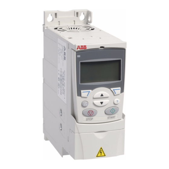
ABB ACS310 User Manual (376 pages)
Brand:
ABB
| Category:
DC Drives
| Size: 5.56 MB
Table of Contents
Www.aotewell.com Industry Automation
5
List of Related Manuals
2
Table of Contents
5
Safety
15
What this Chapter Contains
15
Use of Warnings
15
Safety in Installation and Maintenance
16
Electrical Safety
16
General Safety
17
Safe Start-Up and Operation
17
Safety
17
Applicability
19
Introduction to the Manual
19
Purpose of the Manual
19
Target Audience
19
What this Chapter Contains
19
Contents of this Manual
20
Categorization by Frame Size
21
Related Documents
21
Terms and Abbreviations
21
Quick Installation and Commissioning Flowchart
22
Operation Principle
23
Operation Principle and Hardware Description
23
What this Chapter Contains
23
Product Overview
24
Layout
24
Power Connections and Control Interfaces
25
Type Designation Label
26
Type Designation Key
27
Checking the Installation Site
29
Requirements for the Installation Site
29
Mechanical Installation
29
What this Chapter Contains
29
Required Tools
30
Checking the Delivery
31
Unpacking
31
Installing
32
Install the Drive
32
Fasten Clamping Plates
34
Implementing the AC Power Line Connection
35
Planning the Electrical Installation
35
Selecting the Supply Disconnecting Device (Disconnecting Means)
35
European Union
36
Other Regions
36
What this Chapter Contains
35
Checking the Compatibility of the Motor and Drive
36
Selecting the Power Cables
36
General Rules
36
Alternative Power Cable Types
37
Motor Cable Shield
37
Additional US Requirements
38
Selecting the Control Cables
38
General Rules
38
Relay Cable
39
Control Panel Cable
39
Routing the Cables
39
Control Cable Ducts
40
Protecting the Drive, Input Power Cable, Motor and Motor Cable in Short-Circuit Situations and against Thermal Overload
41
Protecting the Drive and Input Power Cable in Short-Circuit Situations
41
Protecting the Motor and Motor Cable in Short-Circuit Situations
41
Protecting the Drive, Motor Cable and Input Power Cable against Thermal Overload
41
Protecting the Motor against Thermal Overload
41
Implementing a Bypass Connection
42
Protecting the Contacts of Relay Outputs
42
Using Residual Current Devices (RCD) with the Drive
42
Checking the Insulation of the Assembly
45
Drive
45
Input Power Cable
45
Motor and Motor Cable
46
Electrical Installation
45
What this Chapter Contains
45
Checking the Compatibility with IT (Ungrounded) and Corner-Grounded TN Systems
46
Connecting the Power Cables
47
Connection Diagram
47
Connection Procedure
48
Connecting the Control Cables
49
I/O Terminals
49
Default I/O Connection Diagram
52
Connection Procedure
53
Connecting the Embedded Fieldbus
54
Connection Diagram
54
Checking the Installation
55
Installation Checklist
55
How to Start up the Drive
57
How to Start up the Drive Without a Control Panel
58
How to Perform a Manual Start-Up
59
How to Perform a Guided Start-Up
62
Start-Up and Control with I/O
57
What this Chapter Contains
57
How to Control the Drive through the I/O Interface
65
About Control Panels
67
Applicability
67
Control Panels
67
What this Chapter Contains
67
Basic Control Panel
69
Features
69
Overview
70
Operation
71
Output Mode
74
Reference Mode
75
Parameter Mode
76
Copy Mode
78
Basic Control Panel Alarm Codes
79
Assistant Control Panel
80
Features
80
Overview
81
Operation
82
Output Mode
86
Parameters Mode
88
Assistants Mode
91
Changed Parameters Mode
93
Fault Logger Mode
94
Time and Date Mode
95
Parameter Backup Mode
97
IO Settings Mode
100
Application Macros
101
Overview of Macros
101
What this Chapter Contains
101
Summary of the I/O Connections of the Application Macros
103
ABB Standard Macro
104
Default I/O Connections
104
3-Wire Macro
105
Default I/O Connections
105
Alternate Macro
106
Default I/O Connections
106
Motor Potentiometer Macro
107
Default I/O Connections
107
Hand/Auto Macro
108
Default I/O Connections
108
PID Control Macro
109
Default I/O Connections
109
PFC Control Macro
110
Default I/O Connections
110
SPFC Control Macro
111
Default I/O Connections
111
User Macros
112
AC500 Modbus Macro
113
Program Features
115
Start-Up Assistant
115
Introduction
115
Default Order of the Tasks
116
List of the Tasks and the Relevant Drive Parameters
117
Contents of the Assistant Displays
119
What this Chapter Contains
115
Local Control Vs. External Control
119
Local Control
120
External Control
120
Settings
120
Diagnostics
121
Block Diagram: Start, Stop, Direction Source for EXT1
121
Block Diagram: Reference Source for EXT1
121
Reference Types and Processing
122
Settings
122
Diagnostics
122
Reference Trimming
123
Settings
123
Example
124
Programmable Analog Inputs
124
Settings
124
Diagnostics
125
Programmable Analog Output
125
Settings
125
Programmable Digital Inputs
126
Settings
126
Diagnostics
127
Frequency Input
127
Diagnostics
128
Programmable Relay Output
127
Settings
127
Actual Signals
128
Diagnostics
129
Transistor Output
128
Settings
128
Power Loss Ride-Through
129
Settings
129
Acceleration and Deceleration Ramps
130
DC Magnetizing
130
Settings
130
Maintenance Trigger
130
Constant Speeds
131
Critical Speeds
131
Motor Heating Function
131
Settings
131
Diagnostics
131
Custom U/F Ratio
133
Settings
133
Diagnostics
133
IR Compensation
134
Settings
134
Programmable Protection Functions
134
Ai<Min
134
Panel Loss
134
External Fault
134
Stall Protection
134
Motor Thermal Protection
135
Earth Fault Protection
135
Incorrect Wiring
135
Input Phase Loss
136
Operation Limits
136
Settings
136
Pre-Programmed Faults
136
Overcurrent
136
DC Overvoltage
136
DC Undervoltage
136
Drive Temperature
136
Short Circuit
136
Internal Fault
136
Automatic Resets
137
Settings
137
Diagnostics
137
Power Limit
137
Supervisions
137
Parameter Lock
138
Settings
138
PID Control
138
Process Controller PID1
138
External/Trim Controller PID2
138
Block Diagrams
139
Settings
141
Diagnostics
141
Example
141
Sleep Function for the Process PID (PID1) Control
143
Example
144
Settings
145
Diagnostics
145
Motor Temperature Measurement through the Standard I/O
145
Settings
146
Diagnostics
146
Timed Functions
147
Examples
148
Settings
149
User Load Curve
150
Settings
150
Diagnostics
150
Energy Optimizer
151
Settings
151
Energy Saving
151
Diagnostics
151
Pump Cleaning
152
Settings
152
Load Analyzer
153
Peak Value Logger
153
Amplitude Loggers
153
Settings
154
Diagnostics
154
PFC and SPFC Control
155
PFC Control
155
SPFC Control
155
Settings
158
Diagnostics
158
Connection Diagram Example
159
Pipe Fill
160
Reference Ramping
160
PID Reference Ramping
161
Settings
161
Actual Signals and Parameters
163
Terms and Abbreviations
163
What this Chapter Contains
163
Fieldbus Equivalent
164
Default Values with Different Macros
165
Actual Signals in the Short Parameter View
167
Fault History
167
Parameters in the Short Parameter View
167
Reference Select
167
Constant Speeds
167
Analog Inputs
167
14 Relay Outputs
167
16 System Controls
167
20 Limits
167
21 Start/Stop
167
Www.aotewell.com Industry Automation 168 Actual Signals and Parameters
168
Accel/Decel
168
Efb Protocol
168
Parameters in the Short Parameter View no
169
98 Options
169
99 Start-Up Data
169
All Actual Signals
170
Operating Data
170
Fb Actual Signals
173
Fault History
175
All Parameters
177
Start/Stop/Dir
177
Reference Select
179
22 ACCEL/DECEL Acceleration and Deceleration Times. See Group 22
180
Time 2
180
Constant Speeds
183
Analog Inputs
187
Relay Outputs
188
Analog Outputs
191
System Controls
192
Freq in & Tran out
197
20 Limits
199
21 Start/Stop
200
Accel/Decel
204
Critical Speeds
207
Motor Control
208
Maintenance Trig
211
Fault Functions
212
Automatic Reset
218
32 Supervision
220
33 Information
222
Panel Display
223
Motor Temp Meas
228
Timed Functions
230
User Load Curve
234
Process Pid Set 1
236
Process Pid Set 2
247
42 Ext / Trim Pid
249
Pump Protection
251
Energy Saving
256
Pump Cleaning
257
52 Panel Comm
258
Efb Protocol
259
EFB PROTOCOL Embedded Fieldbus Link Settings. See Chapter Control with the Embedded Fieldbus 5301 EFB
259
5302 Efb Station ID
259
Protocol ID
259
5303 Efb Baud Rate
260
5304 Efb Parity
260
5305 Efb Ctrl
260
5306 Efb Ok
260
5307 Efb Crc
260
Communication Profiles
260
Defines the Transfer Rate of the Link
260
Number of Valid Messages Received by the Drive. During
260
Normal Operation, this Number Increases Constantly
260
Load Analyzer
262
Pfc Control
265
Options
283
Start-Up Data
283
Selects the Communication Profile. See Section
260
System Overview
287
Fieldbus Control with the Embedded Fieldbus
289
Setting up Communication through the Embedded Modbus
289
Drive Control Parameters
291
Fieldbus Control Interface
293
Control Word and Status Word
293
References
293
Actual Values
293
Fieldbus References
294
Reference Selection and Correction
294
Fieldbus Reference Scaling
296
Reference Handling
297
Actual Value Scaling
297
Modbus Mapping
298
Register Mapping
299
Function Codes
301
Exception Codes
301
Communication Profiles
302
ABB Drives Communication Profile
302
DCU Communication Profile
307
Alarm and Fault Indications
311
Fault Tracing
311
How to Reset
311
Safety
311
What this Chapter Contains
311
Fault History
312
Alarm Messages Generated by the Drive
313
Alarms Generated by the Basic Control Panel
317
Fault Messages Generated by the Drive
320
Embedded Fieldbus Faults
327
No Master Device
327
Same Device Address
327
Incorrect Wiring
327
Maintenance and Hardware Diagnostics
329
Maintenance Intervals
329
What this Chapter Contains
329
Cooling Fan
330
Replacing the Cooling Fan (Frame Sizes R1
330
Capacitors
331
Reforming the Capacitors
331
Control Panel
332
Cleaning the Control Panel
332
Changing the Battery in the Assistant Control Panel
332
Power Connections
332
Leds
333
Technical Data
335
What this Chapter Contains
335
Ratings
336
Definitions
337
Sizing
338
Derating
338
Fuses and Alternate Short-Circuit Protection
340
Fuses
340
Alternate Short-Circuit Protection
340
Fuses and Mmps
341
Size of Copper Conductor in Cablings
342
Dimensions, Weights and Free Space Requirements
343
Dimensions and Weights
343
Free Space Requirements
344
Losses, Cooling Data and Noise
345
Losses and Cooling Data
345
Noise
346
Terminal and Lead-Through Data for the Power Cables
346
Terminal and Lead-Through Data for the Control Cables
347
Electric Power Network Specification
348
Motor Connection Data
348
Clearance and Creepage Distance
350
Control Connection Data
350
Degrees of Protection
350
Efficiency
350
Ambient Conditions
351
Applicable Standards
352
Materials
352
CE Marking
353
Compliance with the European EMC Directive
353
Compliance with en 61800-3:2004
353
Definitions
353
Category C1
353
Category C2
354
Category C3
354
C-Tick Marking
355
UL Marking
355
UL Checklist
355
Declaration of Incorporation
356
Rohs Marking
356
Dimension Drawings
357
Frame Sizes R0 and R1, IP20 (Cabinet Installation) / UL Open
358
Frame Sizes R0 and R1, IP20 / NEMA 1
359
Frame Size R2, IP20 (Cabinet Installation) / UL Open
360
Frame Size R2, NEMA 1
361
Frame Size R3, IP20 (Cabinet Installation) / UL Open
362
Frame Size R3, NEMA 1
363
Frame Size R4, IP20 (Cabinet Installation) / UL Open
364
Frame Size R4, NEMA 1
365
Index
367
Document Library on the Internet
375
Further Information
375
Product and Service Inquiries
375
Product Training
375
Providing Feedback on ABB Drives Manuals
375
Advertisement
ABB ACS310 User Manual (330 pages)
Brand:
ABB
| Category:
DC Drives
| Size: 4.7 MB
Table of Contents
Table of Contents
4
Safety
14
What this Chapter Contains
14
Use of Warnings
14
Safety in Installation and Maintenance
15
Electrical Safety
15
General Safety
16
Safe Start-Up and Operation
16
Safety 17
16
Applicability
18
Introduction to the Manual
18
Purpose of the Manual
18
Target Audience
18
What this Chapter Contains
18
Contents of this Manual
19
Categorization by Frame Size
20
Related Documents
20
Quick Installation and Commissioning Flowchart
21
Operation Principle
22
Operation Principle and Hardware Description
22
What this Chapter Contains
22
Product Overview
23
Layout
23
Power Connections and Control Interfaces
24
Type Designation Label
25
Type Designation Key
26
Checking the Installation Site
28
Requirements for the Installation Site
28
Mechanical Installation
28
What this Chapter Contains
28
Required Tools
29
Checking the Delivery
30
Unpacking
30
Installing
31
Install the Drive
31
Fasten Clamping Plates
33
Implementing the AC Power Line Connection
34
Planning the Electrical Installation
34
Selecting the Supply Disconnecting Device (Disconnecting Means)
34
European Union
35
Other Regions
35
What this Chapter Contains
34
Checking the Compatibility of the Motor and Drive
35
Selecting the Power Cables
35
General Rules
35
Alternative Power Cable Types
36
Motor Cable Shield
36
Additional US Requirements
37
Selecting the Control Cables
37
General Rules
37
Relay Cable
38
Control Panel Cable
38
Routing the Cables
38
Control Cable Ducts
39
Protecting the Drive, Input Power Cable, Motor and Motor Cable in Short Circuit Situations and against Thermal Overload
40
Protecting the Drive and Input Power Cable in Short-Circuit Situations
40
Protecting the Motor and Motor Cable in Short-Circuit Situations
40
Protecting the Drive, Motor Cable and Input Power Cable against Thermal Overload
41
Protecting the Motor against Thermal Overload
41
Implementing a Bypass Connection
41
Using Residual Current Devices (RCD) with the Drive
41
Protecting the Contacts of Relay Outputs
42
Checking the Insulation of the Assembly
44
Drive
44
Input Power Cable
44
Motor and Motor Cable
45
Electrical Installation
44
What this Chapter Contains
44
Checking the Compatibility with IT (Ungrounded) and Corner Grounded TN Systems
45
Connecting the Power Cables
46
Connection Diagram
46
Connection Procedure
47
Connecting the Control Cables
48
I/O Terminals
48
Default I/O Connection Diagram
51
Connection Procedure
52
Connecting the Embedded Fieldbus
53
Connection Diagram
53
Checking the Installation
54
Installation Checklist
54
How to Start up the Drive
56
How to Start up the Drive Without a Control Panel
57
How to Perform a Manual Start-Up
58
How to Perform a Guided Start-Up
61
Start-Up and Control with I/O
56
What this Chapter Contains
56
How to Control the Drive through the I/O Interface
64
About Control Panels
66
Compatibility
66
Control Panels
66
What this Chapter Contains
66
Basic Control Panel
67
Features
67
Overview
68
Operation
69
Output Mode
71
Reference Mode
72
Parameter Mode
73
Copy Mode
75
Basic Control Panel Alarm Codes
76
Assistant Control Panel
77
Features
77
Overview
78
Operation
79
Output Mode
83
Parameters Mode
85
Assistants Mode
87
Changed Parameters Mode
89
Fault Logger Mode
90
Time and Date Mode
91
Parameter Backup Mode
93
I/O Settings Mode
96
Application Macros
98
Overview of Macros
98
What this Chapter Contains
98
Summary of the I/O Connections of the Application Macros
100
ABB Standard Macro
101
Default I/O Connections
101
3-Wire Macro
102
Default I/O Connections
102
Alternate Macro
103
Default I/O Connections
103
Motor Potentiometer Macro
104
Default I/O Connections
104
Hand/Auto Macro
105
Default I/O Connections
105
PID Control Macro
106
Default I/O Connections
106
PFC Control Macro
107
Default I/O Connections
107
SPFC Control Macro
108
Default I/O Connections
108
User Macros
109
Program Features
110
Start-Up Assistant
110
Introduction
110
Default Order of the Tasks
111
List of the Tasks and the Relevant Drive Parameters
112
Contents of the Assistant Displays
114
What this Chapter Contains
110
Local Control Vs. External Control
114
Local Control
115
External Control
115
Settings
115
Diagnostics
116
Block Diagram: Start, Stop, Direction Source for EXT1
116
Block Diagram: Reference Source for EXT1
116
Reference Types and Processing
117
Settings
117
Diagnostics
117
Reference Trimming
118
Settings
118
Example
119
Programmable Analog Inputs
119
Settings
119
Diagnostics
120
Programmable Analog Output
120
Settings
120
Programmable Digital Inputs
121
Settings
121
Diagnostics
122
Frequency Input
122
Diagnostics
123
Programmable Relay Output
122
Settings
122
Actual Signals
123
Diagnostics
124
Transistor Output
123
Settings
123
Power Loss Ride-Through
124
Settings
124
Acceleration and Deceleration Ramps
125
DC Magnetizing
125
Settings
125
Maintenance Trigger
125
Constant Speeds
126
Critical Speeds
126
Settings
126
Custom U/F Ratio
127
Settings
127
Diagnostics
127
IR Compensation
128
Settings
128
Programmable Protection Functions
128
Ai<Min
128
Panel Loss
128
External Fault 2
128
Stall Protection
128
Motor Thermal Protection
129
Earth Fault Protection
129
Incorrect Wiring
129
Operation Limits
130
Settings
130
Preprogrammed Faults
130
Overcurrent
130
DC Overvoltage
130
DC Undervoltage
130
Drive Temperature
130
Short Circuit
130
Internal Fault
130
Supply Phase Loss
130
Automatic Resets
131
Settings
131
Parameter Lock
131
Supervisions
131
Diagnostics
131
PID Control
132
Process Controller PID1
132
External/Trim Controller PID2
132
Block Diagrams
133
Settings
135
Diagnostics
135
Sleep Function for the Process PID (PID1) Control
136
Example
137
Settings
137
Diagnostics
138
Motor Temperature Measurement through the Standard I/O
138
Settings
139
Diagnostics
139
Timed Functions
140
Example
141
Settings
141
User Load Curve
142
Settings
142
Diagnostics
142
Energy Optimizer
143
Settings
143
Diagnostics
143
Pump Cleaning
143
Settings
144
Load Analyzer
144
Diagnostics
144
PFC and SPFC Control
145
PFC Control
145
SPFC Control
145
Settings
146
Diagnostics
146
Actual Signals and Parameters
148
Terms and Abbreviations
148
What this Chapter Contains
148
Fieldbus Equivalent
149
Default Values with Different Macros
150
Actual Signals in the Short Parameter View
151
04 Fault History
151
Parameters in the Short Parameter View
151
Reference Select
151
Constant Speeds
151
Analog Inputs
151
14 Relay Outputs
151
16 System Controls
151
20 Limits
151
Start/Stop
151
Accel/Decel
152
99 Start-Up Data
152
All Actual Signals
153
Operating Data
153
Fb Actual Signals
155
Fault History
158
All Parameters
160
Start/Stop/Dir
160
Reference Select
162
Constant Speeds
166
Analog Inputs
169
Relay Outputs
170
Analog Outputs
173
System Controls
174
Freq in & Tran out
179
20 Limits
181
21 Start/Stop
182
Accel/Decel
185
Critical Speeds
188
Motor Control
189
Maintenance Trig
192
Fault Functions
193
Automatic Reset
198
32 Supervision
199
33 Information
201
Panel Display
202
Motor Temp Meas
206
Timed Functions
208
User Load Curve
212
Process Pid Set 1
213
Process Pid Set 2
225
Ext / Trim Pid
226
Pump Protection
228
Energy Saving
233
Pump Cleaning
234
Panel Comm
235
Efb Protocol
236
Load Analyzer
238
Pfc Control
241
Options
258
Start-Up Data
259
System Overview
262
What this Chapter Contains
262
Fieldbus Control with Embedded Fieldbus
264
Setting up Communication through the Embedded Modbus
264
Drive Control Parameters
265
Fieldbus Control Interface
267
Control Word and Status Word
267
References
267
Actual Values
267
Fieldbus References
268
Reference Selection and Correction
268
Fieldbus Reference Scaling
270
Reference Handling
271
Actual Value Scaling
271
Modbus Mapping
272
Register Mapping
272
Function Codes
274
Exception Codes
274
Communication Profiles
275
ABB Drives Communication Profile
275
DCU Communication Profile
280
Alarm and Fault Indications
284
How to Reset
284
Safety
284
What this Chapter Contains
284
Fault History
285
Alarm Messages Generated by the Drive
286
Fault Tracing
286
Alarms Generated by the Basic Control Panel
289
Fault Messages Generated by the Drive
292
Embedded Fieldbus Faults
300
No Master Device
300
Same Device Address
300
Incorrect Wiring
300
Maintenance and Hardware Diagnostics
302
Maintenance Intervals
302
What this Chapter Contains
302
Cooling Fan
303
Replacing the Cooling Fan (Frame Sizes R1
303
Capacitors
304
Reforming the Capacitors
304
Power Connections
304
Control Panel
305
Cleaning the Control Panel
305
Changing the Battery in the Assistant Control Panel
305
Leds
305
Technical Data
306
What this Chapter Contains
306
Ratings
307
Definitions
307
Sizing
308
Derating
308
Power Cable Sizes and Fuses
309
Dimensions, Weights and Free Space Requirements
310
Dimensions and Weights
310
Free Space Requirements
310
Losses, Cooling Data and Noise
311
Losses and Cooling Data
311
Noise
312
Terminal and Lead-Through Data for the Control Cables
312
Terminal and Lead-Through Data for the Power Cables
312
Electric Power Network Specification
313
Motor Connection Data
313
Control Connection Data
314
Degrees of Protection
314
Efficiency
314
Ambient Conditions
315
Applicable Standards
316
Materials
316
CE Marking
317
Compliance with the European EMC Directive
317
Compliance with en 61800-3:2004
317
Definitions
317
Category C2
317
Category C3
318
UL Marking
318
UL Checklist
318
C-Tick Marking
319
Rohs Marking
319
Liability Limits
320
Patent Protection in the USA
320
Dimensions
322
Frame Sizes R0 and R1, IP20 (Cabinet Installation) / UL Open
323
Frame Sizes R0 and R1, IP20 / NEMA 1
324
Frame Size R2, IP20 (Cabinet Installation) / UL Open
325
Frame Size R2, NEMA 1
326
Frame Size R3, IP20 (Cabinet Installation) / UL Open
327
Frame Size R3, NEMA 1
328
Frame Size R4, IP20 (Cabinet Installation) / UL Open
329
Frame Size R4, NEMA 1
330
ABB ACS310 Quick Start Manual (48 pages)
PLC and drives integration using Modbus RTU
Brand:
ABB
| Category:
Controller
| Size: 2.6 MB
Table of Contents
Table of Contents
2
Introduction
4
Safety Instructions
4
Limitations
4
Fieldbus Grounding
6
Fieldbus Shield
6
End Termination
6
Pull Up/Pull down Resistors
6
Drives with Embedded Fieldbus
7
Fieldbus Modules for ABB Drives
8
Common Recommendations
8
ABB Cable TK505
9
AC500 COM1 - Master at the Bus Line End
11
AC500 COM2 - Master at the Bus Line End
11
AC500-Eco COM1 - Master at the Bus Line End
11
AC500-Eco COM2 - Master at the Bus Line End
12
Drive Configuration
13
Starting up ACS310 Drives with Embedded Modbus RTU
14
Starting up ACS355 Drives with FMBA-01 Modbus RTU Adapter
15
Starting up ACS800 Drives with RMBA-01 Modbus RTU Adapter
17
Starting up ACS850, ACQ810 Drives with Embedded Modbus RTU
18
Starting up ACS880 Drives with FSCA-01 Modbus RTU Adapter
19
Starting up ACSM1 Drives with FSCA-01 Modbus RTU Adapter
20
Install Drives Library
21
Control Builder Plus for PLC and Drives
22
Hardware Configuration
22
IP Configuration of CPU (for Ethernet Connection between PC and PLC)
24
Codesys
25
CODESYS Tabs
25
Library Manager
26
PLC Logic
27
Download Program to PLC
32
Create Boot Project
33
Test the Program
34
Read and Write more Data between PLC and Drive (Optional)
36
Visualizations
43
Add more Drives (Optional)
46
Actualization Rate
47
Other Useful Documentation
47
Revision
47
Advertisement
ABB ACS310 User Manual (40 pages)
Brand:
ABB
| Category:
DC Drives
| Size: 2.37 MB
Table of Contents
List of Related Manuals
2
Purpose of the Manual
2
Applicability
2
Table of Contents
3
1 Safety
5
Safety in Installation and Maintenance
5
Safe Start-Up and Operation
6
2 Hardware Description
7
Power Connections and Control Interfaces
7
Type Designation Key
8
3 Mechanical Installation
9
Installing
9
4 Electrical Installation
13
Checking the Compatibility with IT (Ungrounded) and Corner Grounded TN Systems
13
Connecting the Power Cables
14
Connecting the Control Cables
16
Installation Checklist
18
5 Start-Up and Control with I/O
19
How to Start up the Drive
19
How to Control the Drive through the I/O Interface
26
6 Actual Values and Parameters in the Short View
27
Terms and Abbreviations
27
Fieldbus Equivalent
27
Default Values with Different Macros
28
Actual Signals in the Short Parameter View
29
Parameters in the Short Parameter View
29
7 Technical Data
35
Ratings
35
Power Cable Sizes and Fuses
36
UL Checklist
37
Further Information
39
Product and Service Inquiries
39
Product Training
39
ABB ACS310 User's Manual And Safety Manual (40 pages)
Short Form
Brand:
ABB
| Category:
Controller
| Size: 1.77 MB
ABB ACS310 Installation Instructions (4 pages)
Brand:
ABB
| Category:
DC Drives
| Size: 0.67 MB
ABB ACS310 Installation Instructions (4 pages)
Brand:
ABB
| Category:
Media Converter
| Size: 0.4 MB
Advertisement
Related Products
ABB ACS 311-1P1-1
ABB ACS 311-1P6-1
ABB ACS 311-2P1-1
ABB ACS 311-2P7-1
ABB ACS 311-4P1-1
ABB ACS380-04xC
ABB ACS355-03E-08A8-4+B063
ABB ACS355 UL 4X
ABB ACS30108P73DE
ABB ACS 301-2P1-1
ABB Categories
Industrial Equipment
Controller
Measuring Instruments
Battery Charger
DC Drives
More ABB Manuals
Login
Sign In
OR
Sign in with Facebook
Sign in with Google
Upload manual
Upload from disk
Upload from URL