Advertisement
Advertisement
Table of Contents

Related Manuals for Asus IPILP-AR


Summary of Contents for Asus IPILP-AR
- Page 1 IPILP-AR...
-
Page 2: Table Of Contents
E3030 First Edition V1 January 2007 Contents IPILP-AR specifications summary............. iii Motherboard layout................1 Central Processing Unit (CPU)............2 2.1 Enhanced Intel SpeedStep Technology (EIST) ..... 2 ®. 2.2 Installing the CPU..............3 System memory................5 3.1 Memory configurations............. 5 3.2 Installing a DIMM. -
Page 3: Ipilp-Ar Specifications Summary
IPILP-AR specifications summary CPU. Intel socket LGA775 Conroe/ Celeron processor ® 2006FMB (TDP=65W) Chipset Nortbridge: Intel 945G GMCH ® Southbridge: Intel ICH7DH ® Front Side Bus 1066/800/533 MHz Memory Dual channel memory architecture 2 x 240-pin DIMM sockets support up to 2 GB non- ECC 1.8V DDR SD RAM (Register DIMM is not... -
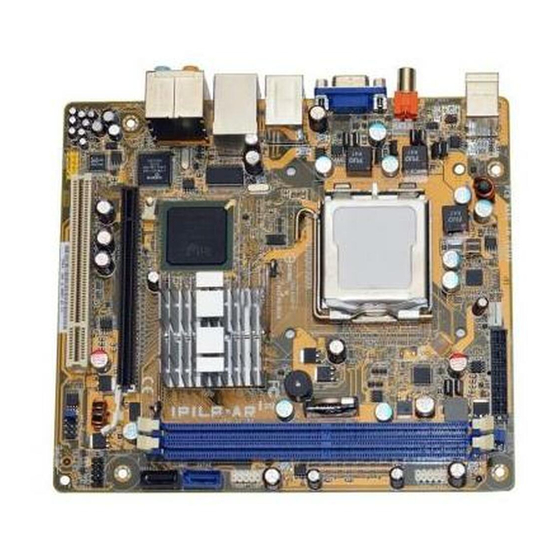
Page 5: Motherboard Layout
Motherboard layout 17.3cm (6.8in) ATXPWR1 CLEAR P.W PS/2KBMS SYS_FAN1 CLEAR CMOS T: Mouse B: Keyboard LGA775 SPDIF_OUT1 SPDIF1 BAT1 BUZZ1 1394_USB1 LAN_USB1 Intel 945G Intel ICH7DH AUDIO1 Agere LFW3226 PCIEX1 ALC888 F_PANEL1 PCI1 F_AUDIO1 8MB SPI Flash ASUS IPILP-AR... -
Page 6: Central Processing Unit (Cpu)
ASUS will shoulder the cost of repair only if the damage is shipment/transit-related. • Keep the cap after installing the motherboard. ASUS will process Return Merchandise Authorization (RMA) requests only if the motherboard comes with the cap on the LGA775 socket. -
Page 7: Installing The Cpu
Installing the CPU To install a CPU: Locate the CPU socket on the motherboard. IPILP-AR CPU Socket 775 Before installing the CPU, make sure that the cam box is facing towards you and the load lever is on your left. - Page 8 ® ® The motherboard supports Intel LGA775 processors with the Intel Enhanced ® Memory 64 Technology (EM64T), Enhanced Intel SpeedStep Technology (EIST), and Hyper-Threading Technology. Refer to the Appendix for more information on these CPU features. ASUS IPILP-AR...
-
Page 9: System Memory
The motherboard comes with two Double Data Rate (DDR) Dual Inline Memory Modules (DIMM) sockets. The following figure illustrates the location of the DDR DIMM sockets: IPILP-AR 240-pin DDR2 DIMM sockets Memory configurations You may install 256 MB, 512 MB, 1 GB, and 2 GB unbuffered non-ECC DDR DIMMs into the DIMM sockets. -
Page 10: Installing A Dimm
Simultaneously press the retaining clips outward to unlock the DIMM. Support the DIMM lightly with your fingers when pressing the retaining clips. The DIMM might get damaged when it flips out with extra force. Remove the DIMM from the socket. ASUS IPILP-AR... -
Page 11: Expansion Slots
PCI Express specifications. The figure above shows a graphics card installed on the PCI Express x16 slot. This motherboard supports an ASUS R-DVI-ADD2 card for DVI output. The figure below shows an R-DVI-ADD2 card installed on the PCI Express x16 slot. -
Page 12: Jumper
4. Hold down the <Del> key during the boot process and enter BIOS setup to re-enter data. Except when clearing the RTC RAM, never remove the cap from the default position. Removing the cap will cause system boot failure! CLEAR CMOS Clear CMOS Normal (Default) IPILP-AR Clear RTC RAM ASUS IPILP-AR... - Page 13 5. Move the jumper cap from pins 1-2 to pins 2-3. 6. Hold down the <F1> key during the boot process and enter BIOS setup to verify that the password has been cleared. CLEAR P.W Clear Password Normal (Default) IPILP-AR Clear password setting ASUS IPILP-AR...
-
Page 14: Connectors
Line Out port (lime). This port connects a headphone or a speaker. In 4- channel, 6-channel, and 8-channel mode, the function of this port becomes Front Speaker Out. Microphone port (pink). This port connects a microphone. ASUS IPILP-AR... - Page 15 11. VGA Graphic Adapter (VGA) port. This 15-pin port is for a VGA monitor or other VGA-compatible devices. 12. Coaxial S/PDIF Out port. This port connects an external audio output device via a coaxial S/PDIF cable. 13. PS/2 keyboard port (purple). This port is for a PS/2 keyboard. ASUS IPILP-AR...
-
Page 16: Internal Connectors
480 Mbps connection speed. FRONT_USB1 V_FP_USBPWR V_FP_USBPWR USB_FP_P0- USB_FP_P1- USB_FP_P0+ USB_FP_P1+ FRONT_USB2 V_FP_USBPWR0 V_FP_USBPWR0 USB_FP_P2- USB_FP_P32- USB_FP_P2+ USB_FP_P3+ IPILP-AR USB 2.0 connectors Never connect a 1394 cable to the USB connectors. Doing so will damage the motherboard! ASUS IPILP-AR... - Page 17 When using the connectors in Standard IDE mode, connect the primary (boot) hard disk drive to the SATA1 connector. 4. Front headphone connector (10-1 pin F_AUDIO1) This connector is for a chassis-mounted front panel headphone port. F_AUDIO1 IPILP-AR Front audio connector ASUS IPILP-AR...
- Page 18 These are not jumpers! DO NOT place jumper caps on the fan connectors! SYS_FAN1 IPILP-AR SYS fan connector Digital audio connector (4-1 pin SPDIF_OUT2) This connector is for an additional Sony/Philips Digital Interface (S/PDIF) port(s).
- Page 19 System panel connector (10-1 pin F_PANEL1) This connector supports several chassis-mounted functions. PWR LED PWR BTN F_PANEL PIN1 IPILP-AR System panel connector HD LED RESET • System power LED (2-pin PWR LED) This 2-pin connector is for the system power LED. Connect the chassis power LED cable to this connector.
- Page 20 ASUS IPILP-AR...