D-Link DGS-1210/ME User Manual
Metro ethernet switch series
Hide thumbs
Also See for DGS-1210/ME:
- Reference manual (522 pages) ,
- Hardware installation manual (53 pages) ,
- Reference manual (465 pages)
Table of Contents
Advertisement
Advertisement
Table of Contents

Related Manuals for D-Link DGS-1210/ME


Summary of Contents for D-Link DGS-1210/ME
-
Page 2: Table Of Contents
Table of Contents DGS-1210 series Metro Ethernet Managed Switch User Manual Table of Contents Table of Contents ............................. i About This Guide ............................. 1 Terms/Usage ..............................1 Copyright and Trademarks ..........................1 Product Introduction ........................... 2 Switch Description ............................2 Front Panel Description.......................... - Page 3 System > IEEE802.3az EEE Settings ...................... 27 System > SMTP Service > SMTP Server Settings .................. 27 System > SMTP Service > SMTP Service ....................28 System > D-Link Discover Protocol Settings .................... 28 Configuration > Jumbo Frame ........................29 Configuration > 802.1Q VLAN ........................29 Configuration >...
- Page 4 Table of Contents DGS-1210 series Metro Ethernet Managed Switch User Manual Configuration > MLD Snooping > MLD Host Table .................. 44 Configuration > Port Mirroring ........................44 Configuration > Loopback Detection ......................45 Configuration > SNTP Settings > Time Settings ..................46 Configuration >...
- Page 5 Table of Contents DGS-1210 series Metro Ethernet Managed Switch User Manual Security > Access Authentication Control > Authentication Policy Settings ..........75 Security > Access Authentication Control > Application Authentication Settings ........75 Security > Access Authentication Control > Authentication Server Group ..........75 Security >...
- Page 6 Table of Contents DGS-1210 series Metro Ethernet Managed Switch User Manual PoE > PoE System Settings (DGS-1210-28P only) ................110 Time-Based PoE > Time Range Settings ....................111 LLDP > LLDP Global Settings ........................ 112 LLDP > Basic LLDP Port Settings ......................112 LLDP >...
-
Page 7: About This Guide
Configuration: Information about the function descriptions and configuration settings. Terms/Usage In this guide, the term “Switch” (first letter capitalized) refers to DGS-1210/ME Metro Ethernet Switch, and “switch” (first letter lower case) refers to other Ethernet switches. Some technologies refer to terms “switch”, “bridge”... -
Page 8: Switch Description
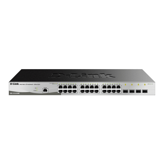
Side Panel Description Switch Description The DGS-1210/ME Metro Ethernet Switch is equipped with Copper ports (10/100/1000Mbps) and SFP ports (1000Mbps) that can be used to attach various networking devices to the network like Computers, Notebooks, Print Servers, Network Attached Storage devices, IP Cameras, VoIP PBX devices, and other Switches. - Page 9 Optical Transceiver product, Rated Laser Class I. 3.3Vdc. LED Indicators The Switch supports LED indicators for Power, Console, Fan, and Link/Act for each port. The following shows the LED indicators for the DGS-1210/ME Metro Ethernet Switch along with an explanation of each indicator.
- Page 10 1 Product Introduction DGS-1210 series Metro Ethernet Managed Switch User Manual Figure 1.5 –LED Indicators on DGS-1210/ME SERIES Location LED Indicative Color Status Description Solid Light Power on. Power Green Light off Power off. Solid Light Console on. Console Green Blinking POST is in progress.
-
Page 11: Gigabit Fiber Ports
Figure 1-10. Side panels of the DGS-1210/ME SERIES Gigabit Fiber Ports The DGS-1210/ME Series features support four Small Form Factor Portable (SFP) ports (optional). See the diagram below to view the two SFP port modules being plugged into the Switch. -
Page 12: Product Introduction
1 Product Introduction DGS-1210 series Metro Ethernet Managed Switch User Manual Figure 1-11. Inserting the SFP modules into the Switch Figure 1-12. Installing the SFP Module The Switch is equipped with SFP ports, which are to be used with fiber-optical transceiver cabling in order to uplink various other networking devices for a gigabit link that may span great distances. -
Page 13: Hardware Installation
2 Hardware Installation DGS-1210 series Metro Ethernet Managed Switch User Manual Hardware Installation This chapter provides unpacking and installation information for the D-Link DGS-1210/ME Metro Ethernet Switch. Step 1: Unpacking Open the shipping carton and carefully unpack its contents. Please consult the packing list located in the User Manual to make sure all items are present and undamaged. -
Page 14: Step 3 - Plugging In The Ac Power Cord
2 Hardware Installation DGS-1210 series Metro Ethernet Managed Switch User Manual Then, use the screws provided with the equipment rack to mount the switch in the rack. Figure 2.3 – Mount the Switch in the rack or chassis Please be aware of following safety Instructions when installing: A) Elevated Operating Ambient - If installed in a closed or multi-unit rack assembly, the operating ambient temperature of the rack environment may be greater than room ambient. -
Page 15: Power Failure
2 Hardware Installation DGS-1210 series Metro Ethernet Managed Switch User Manual Figure 2.5 – Plugging the switch into an outlet Power Failure As a precaution, the switch should be unplugged in case of power failure. When power is resumed, plug the switch back in. -
Page 16: Getting Started
This chapter introduces the management interface of D-Link DGS1210/ME Metro Ethernet Switch. Management Options The D-Link DGS1210/ME Metro Ethernet Switch can be managed through any port on the device by using the Web-based Management, out-of band through the console port on the front/back panel and in-band... -
Page 17: Web-Based Management
3 Getting Started DGS-1210 series Metro Ethernet Managed Switch User Manual a subnet mask of 255.0.0.0. Enter 10.90.90.90 (the factory default IP address) in the address bar of your web browser and press <Enter>. Figure 3.2 –Enter the IP address 10.90.90.90 in the web browser NOTE: The switch's factory default IP address is 10.90.90.90 with a subnet mask of 255.0.0.0 and a default gateway of 0.0.0.0. -
Page 18: Configuration
4 Configuration DGS-1210 series Metro Ethernet Managed Switch User Manual Configuration The features and functions of the D-Link DGS1210/ME Metro Ethernet Switch can be configured for optimum use through the Web-based user interface. Web-based Management After press the OK button in Logon Dialog Box, you will see the screen below: Figure 4.1 –... -
Page 19: Tool Bar > Save Menu
4 Configuration DGS-1210 series Metro Ethernet Managed Switch User Manual Finally, by clicking on the D-Link logo at the upper-left corner of the screen you will be redirected to the local D-Link website. Tool Bar > Save Menu The Save Menu provides Save Configuration and Save Log functions. -
Page 20: Configuration Backup & Restore
4 Configuration DGS-1210 series Metro Ethernet Managed Switch User Manual Figure 4.7 – Tool Menu > Reboot Device Configuration Backup & Restore Allow the current configuration settings to be saved to a file (not including the password), and if necessary, you can restore configuration settings from this file. -
Page 21: Tool Bar > Online Help
The Online Help provides two ways of online support: Figure 4.10 – Online Help D-Link Support Site: This will lead you to the D-Link website where you can find online resources such as updated firmware images. User Guide: This can offer an immediate reference for the feature definition or configuration guide. -
Page 22: Device Information
4 Configuration DGS-1210 series Metro Ethernet Managed Switch User Manual Figure 4.11 –Function Tree Device Information The Device Information provides an overview of the switch, including essential information such as firmware & hardware information, and IP address. It also offers an overall status of common software features: STP: Click Settings to link to Configuration >... -
Page 23: System > System Settings
4 Configuration DGS-1210 series Metro Ethernet Managed Switch User Manual Figure 4.12 – Device Information System > System Settings The System Setting allows the user to configure the IP address and the basic system information of the Switch. IP Information: There are two ways for the switch to obtain an IP address: Static and DHCP (Dynamic Host Configuration Protocol). -
Page 24: System > Firmware Information
4 Configuration DGS-1210 series Metro Ethernet Managed Switch User Manual Figure 4.13 – System > System Settings System > Firmware Information The Serial Port Settings page displays the information of firmware. Figure 4.14 – System > Firmware Information System > IPv6 System Settings The IPv6 System Settings page allow user to configure the IPv6 system information. -
Page 25: System > Ipv6 Route Settings
4 Configuration DGS-1210 series Metro Ethernet Managed Switch User Manual NS Retransmit Time Settings: NS Retransmit Time (1-3600): Enter the Neighbor solicitation’s retransmit timer in second here. Specifies the NS retransmit time for IPv6. The field range is 1-3600, and default is 1 second. Automatic Link Local State Settings: Automatic Link Local Address: Specifies the automatic link is enabled or disabled. -
Page 26: System > Dhcp Auto Configuration
4 Configuration DGS-1210 series Metro Ethernet Managed Switch User Manual State: Use the drop-down menu to select All, Address, Static or Dynamic. When the user selects address from the drop-down menu, the user will be able to enter an IP address in the space provided next to the state option. -
Page 27: System > Port Configuration > Port Settings
4 Configuration DGS-1210 series Metro Ethernet Managed Switch User Manual Firmware Upgrade State: Information of firmware upgrade - success or failure. Port Security Violation: Events of port security violation. IMPB Violation: Specifies the device to send notifications when IMPB violation detected. Loopback occurring/recovery: Specifies the device to send notifications when loopback occurring / recovery. -
Page 28: System > Port Configuration > Port Error Disabled
4 Configuration DGS-1210 series Metro Ethernet Managed Switch User Manual Figure 4.21 – System > Port Configuration > Port Description From Port / To Port: Specify the range of ports to describe. Medium Type: Depending on the selected port type, two options for user. Copper and Fiber_1G. Description: Specify the description of ports. -
Page 29: System > Snmp Settings > Snmp User Table
4 Configuration DGS-1210 series Metro Ethernet Managed Switch User Manual Figure 4.23 – System > SNMP Settings > SNMP Global State System > SNMP Settings > SNMP User Table This page is used to maintain the SNMP user table for the use of SNMPv3. SNMPv3 allows or restricts users using the MIB OID, and also encrypts the SNMP messages sent out between users and Switch. -
Page 30: System > Snmp Settings > Snmp View Table
4 Configuration DGS-1210 series Metro Ethernet Managed Switch User Manual AuthPriv – Both authorization and encryption are required for packets sent between the Switch and SNMP manger. Notify View Name: Specify a SNMP group name for users that can receive SNMP trap messages generated by the Switch's SNMP agent. -
Page 31: System > Snmp Settings > Snmp Host Table
4 Configuration DGS-1210 series Metro Ethernet Managed Switch User Manual Click Apply to create a new SNMP community, Delete to remove an existing community. System > SNMP Settings > SNMP Host Table This page is to configure the SNMP trap recipients. Host IP Address: Select IPv4 or IPv6 and specify the IP address of SNMP management host. -
Page 32: System > User Accounts
4 Configuration DGS-1210 series Metro Ethernet Managed Switch User Manual Fiber Port Link Up / Link Down: Fiber port connection information. Twisted Pair Port Link Up / Link Down: Twisted pair port connection information. RSTP Port State Change: Events of a RSTP port state changes. Firmware Upgrade State: Information of firmware upgrade - success or failure. -
Page 33: System > Pppoe Circuit Id Insertion Settings
4 Configuration DGS-1210 series Metro Ethernet Managed Switch User Manual ARP Aging Time (0-65535): Specifies the ARP aging time on the Switch. The range is from 0 to 65535 with a default setting of 5 minutes. System > PPPoE Circuit ID Insertion Settings The PPPoE Circuit ID Insertion Settings page specifies the configuration of settings. -
Page 34: System > Password Encryption
4 Configuration DGS-1210 series Metro Ethernet Managed Switch User Manual Port (1-65535): The TCP port number. TCP ports are numbered between 1 and 65535. The well-known TCP port for the Telnet protocol is 23. System > Password Encryption The Password Encryption page is used to enable or disable the password encryption state. Select Enabled and click Apply to make effect. -
Page 35: System > System Log Configuration > System Log Settings
4 Configuration DGS-1210 series Metro Ethernet Managed Switch User Manual History Size (1-500): The maximum number of entries listed in the history log used for notification. Up to 500 entries can be specified. Click Apply for the changes to take effect. To change MAC notification settings for a port or group of ports on the Switch, configure the following parameters. -
Page 36: System > Time Profile
4 Configuration DGS-1210 series Metro Ethernet Managed Switch User Manual System > Time Profile The Time Profile page allows users to configure the time profile settings of the device. Figure 4.42 – System > Time Profile Settings Range Name: Specifies the profile name. Date: Select Date and specifies the From Day and To Day of the time profile. -
Page 37: System > Ieee802.3Az Eee Settings
4 Configuration DGS-1210 series Metro Ethernet Managed Switch User Manual Port Shut-off - The Port Shut-off state has high priority (the priority rule is the same as LED.) Therefore, if the Port Shut-off sate is already disabled the Time Profile function will not take effect. System Hibernation - In this mode, switches get most power-saving figures since main chipsets (both MAC and PHY) are disabled for all ports, and energy required to power the CPU is minimal. -
Page 38: System > Smtp Service > Smtp Service
Once the message is ready, click Send to send this mail to all recipients configured on the Switch for SMTP. System > D-Link Discover Protocol Settings For the D-Link Discovery Protocol (DDP) supported device, this page is an option for you to disable DDP or configure the DDP packet report timer. -
Page 39: Configuration > Jumbo Frame
DGS-1210 series Metro Ethernet Managed Switch User Manual Figure 4.47 – System > D-Link Discover Protocol Settings D-Link Discover Protocol Report Timer (Seconds): Configure the report timer of D-Link Discover Protocol in seconds. The values are 30, 60, 90, 120 or Never. - Page 40 4 Configuration DGS-1210 series Metro Ethernet Managed Switch User Manual Figure 4.49 – Configuration > 802.1Q VLAN Click Add VID to create a new VID group, assigning ports from 01 to 10 as Untag, Tag, Forbidden or Not Member. Enable or disable the VLAN Advertisement. A port can be untagged in only one VID. To save the VID group, click Apply.
-
Page 41: Configuration > 802.1Q Management Vlan
4 Configuration DGS-1210 series Metro Ethernet Managed Switch User Manual Figure 4.51 - Configuration > 802.1Q VLAN > Example VIDs Click the VID number, the configuration of VLAN group which selected by user will displayed. Change the port assignment then click Apply to implement changes made. User can also click the Previous Page to the go back to the previous page. -
Page 42: Configuration > Vlan Status
4 Configuration DGS-1210 series Metro Ethernet Managed Switch User Manual Configuration > VLAN Status The VLAN Status page is for user to search the VLAN which has already existed on the Switch. Figure 4.55 - Configuration > VLAN Status Enter the VLAN ID or VLAN Name then click Find to show the existed VLAN. Configuration >... -
Page 43: Configuration > Gvrp Timer Settings
4 Configuration DGS-1210 series Metro Ethernet Managed Switch User Manual Figure 4.57 - Configuration > GVRP Settings From Port/To Port: These two fields allow user to specify the range of ports that will be included in the Port- based VLAN that user is creating using the 802.1Q Port Settings page. PVID (1-4094): The read-only field in the 802.1Q Port Table shows the current PVID assignment for each port, which may be manually assigned to a VLAN when created in the Settings table. -
Page 44: Configuration > Qinq > Qinq Settings
4 Configuration DGS-1210 series Metro Ethernet Managed Switch User Manual Join Time (100-100000): Indicates the time in milliseconds that PDUs are transmitted. The default value is 200ms. Leave Time (100-100000): Indicates the amount of time in milliseconds that the device waits before leaving its GARP state. -
Page 45: Configuration > Qinq > Vlan Translation Cvid Entry Settings
4 Configuration DGS-1210 series Metro Ethernet Managed Switch User Manual Configuration > QinQ > VLAN Translation CVID Entry Settings The VLAN Translation translates the VLAN ID carried in the data packets it receives from private networks into those used in the Service Providers network. Figure 4.60 - Configuration >... -
Page 46: Configuration > 802.1V Protocol Vlan > 802.1V Protocol Vlan Settings
4 Configuration DGS-1210 series Metro Ethernet Managed Switch User Manual Protocol Value: Enter a value for the group. The protocol value is used to identify a protocol of the frame type specified. The form of the input is 0x0 to 0xffff. Configuration >... -
Page 47: Configuration > Link Aggregation > Lacp Port Settings
4 Configuration DGS-1210 series Metro Ethernet Managed Switch User Manual Figure 4.64 – Configuration > Link Aggregation > Port Trunkings Link Aggregation Algorithm: Specify the algorithm to be MAC Source, MAC Destination, MAC Source Destination, IP Source, IP Destination or IP Source Destination, and then click Apply to implement changes made. -
Page 48: Configuration > Bpdu Protection Settings
4 Configuration DGS-1210 series Metro Ethernet Managed Switch User Manual Active - Active LACP ports are capable of processing and sending LACP control frames. This allows LACP compliant devices to negotiate the aggregated link so the group may be changed dynamically as needs require. -
Page 49: Configuration > Igmp Snooping > Igmp Snooping
IGMP snooping can help reduce cluttered traffic on the LAN. With IGMP snooping enabled globally, the DGS-1210/ME Metro Ethernet Switch will forward multicast traffic only to connections that have group members attached. The settings of IGMP snooping is set by each VLAN individually. -
Page 50: Configuration > Igmp Snooping > Igmp Access Control Settings
4 Configuration DGS-1210 series Metro Ethernet Managed Switch User Manual Figure 4.68 – Configuration > IGMP Snooping > IGMP Snooping-Parameters Settings Click Edit button to enter the Router Port Settings page, and the ports to be assigned as router ports for IGMP snooping for the VLAN. -
Page 51: Configuration > Igmp Snooping > Ism Vlan Settings
4 Configuration DGS-1210 series Metro Ethernet Managed Switch User Manual Figure 4.71 – Configuration > IGMP Snooping > IGMP Access Control Settings From Port/To Port: Select the port ranges to be configured. Status: Enable or disable the IGMP Access Control of specified ports. Click Apply to take effect. -
Page 52: Configuration > Igmp Snooping > Host Table
4 Configuration DGS-1210 series Metro Ethernet Managed Switch User Manual IPv4 Replace Source: This field is used to replace the source IPv4 address of incoming packets sent by the host before being forwarded to the source port. IPv6 Replace Source IP: This field is used to replace the source IPv6 address of incoming packets sent by the host before being forwarded to the source port. -
Page 53: Configuration > Igmp Snooping > Max Multicast Group Settings
4 Configuration DGS-1210 series Metro Ethernet Managed Switch User Manual Figure 4.75- Configuration > IGMP Snooping > Limited Multicast Range Settings From Port / To Port: Specify the port ranges to be configured. Profile Type: Specify the profile type is IPv4 or IPv6. Profile ID: Specify the Profile ID. -
Page 54: Configuration > Mld Snooping > Mld Host Table
4 Configuration DGS-1210 series Metro Ethernet Managed Switch User Manual Figure 4.77- Configuration > MLD Snooping > MLD Snooping Settings MLD Snooping: Enable or disable the MLD Snooping. MLD Global Settings: Host Timeout (130-153025 sec): Specifies the time interval in seconds after which a port is removed from a Multicast Group. -
Page 55: Configuration > Loopback Detection
4 Configuration DGS-1210 series Metro Ethernet Managed Switch User Manual Figure 4.79 – Configuration > Port Mirroring Port Mirroring: Enables or Disables the port mirroring feature. Target Port: Specifies the target port. Selection options for the Source Ports are as follows: TX (transmit) mode: Duplicates the data transmitted from the source port and forwards it to the Target Port. -
Page 56: Configuration > Sntp Settings > Time Settings
4 Configuration DGS-1210 series Metro Ethernet Managed Switch User Manual Recover Time (0 or 60-1000000): Time allowed (in seconds) for recovery when a Loopback is detected. The Loop Detection Recover Time can be set at 0 seconds, or 60 to 1000000 seconds. Entering 0 will disable the Loop Detection Recover Time. -
Page 57: Configuration > Dhcp/Bootp Relay > Dhcp/Bootp Relay Global Settings
4 Configuration DGS-1210 series Metro Ethernet Managed Switch User Manual Figure 4.82 – Configuration > SNTP > TimeZone Settings Daylight Saving Time State: Enable or disable the DST Settings. Daylight Saving Time Offset: Use this drop-down menu to specify the amount of time that will constitute your local DST offset - 30, 60, 90, or 120 minutes. -
Page 58: Configuration > Dhcp/Bootp Relay > Dhcp/Bootp Relay Interface Settings
4 Configuration DGS-1210 series Metro Ethernet Managed Switch User Manual Enabled – When this field is toggled to Enabled the relay agent will insert and remove DHCP relay information (option 82 field) in messages between DHCP servers and clients. When the relay agent receives the DHCP request, it adds the option 82 information, and the IP address of the relay agent (if the relay agent is configured), to the packet. -
Page 59: Configuration > Dhcp Local Relay Settings
4 Configuration DGS-1210 series Metro Ethernet Managed Switch User Manual Figure 4.84 - Configuration > DHCP/BOOTP Relay > DHCP/BOOTP Relay Interface Settings Interface: The IP interface on the Switch that will be connected directly to the Server. Server IP: Enter the IP address of the DHCP/BOOTP server. Up to four server IPs can be configured per IP Interface. -
Page 60: Configuration > Spanning Tree > Stp Bridge Global Settings
4 Configuration DGS-1210 series Metro Ethernet Managed Switch User Manual DHCPv6 Relay Status: Specifies whether DHCPv6 Relay is enabled on the device. Enabled – Enables DHCPv6 Relay on the device. Disabled – Disables DHCPv6 Relay on the device. This is the default value. DHCPv6 Relay Hops Count Limit (1-32): The field allows and entry between 1 and 32 to define the maximum number of router hops DHCPv6 messages can be forwarded. - Page 61 4 Configuration DGS-1210 series Metro Ethernet Managed Switch User Manual Figure 4.87 - Configuration > Spanning Tree > STP Bridge Global Settings Spanning Tree Protocol: Specify the Spanning Tree Protocol to be Enabled or Disabled. STP Version: You can choose MSTP, RSTP or STP Compatible. The default setting is MSTP. Bridge Priority: This value between 0 and 61410 specifies the priority for forwarding packets: the lower the value, the higher the priority.
-
Page 62: Configuration > Spanning Tree > Stp Port Settings
4 Configuration DGS-1210 series Metro Ethernet Managed Switch User Manual Configuration > Spanning Tree > STP Port Settings STP can be set up on a port per port basis. In addition to setting Spanning Tree parameters for use on the switch level, the Switch allows for the configuration of the groups of ports, each port-group of which will have its own spanning tree, and will require some of its own configuration settings. -
Page 63: Configuration > Spanning Tree > Mst Configuration Identification
4 Configuration DGS-1210 series Metro Ethernet Managed Switch User Manual Restricted Role: Toggle between True and False to set the restricted role state of the packet. If set to True, the port will never be selected to be the Root port. The default value is False. Restricted TCN: Toggle between True and False to set the restricted TCN of the packet. -
Page 64: Configuration > Spanning Tree > Mstp Port Information
4 Configuration DGS-1210 series Metro Ethernet Managed Switch User Manual Figure 4.90 - Configuration > Spanning Tree > STP Instance Settings To modify an entry on the table, click the Edit button. To view more information about and entry on the table at the top of the window, click the view button. -
Page 65: Configuration > Ethernet Oam > Ethernet Oam Event Configuration
4 Configuration DGS-1210 series Metro Ethernet Managed Switch User Manual Figure 4.92 - Configuration > Ethernet OAM > Ethernet OAM Port Settings From Port/To Port: Select a range of ports to be configured. Mode: Use the drop-down menu to select to operate in either Active or Passive. The default mode is Active. State: Use the drop-down menu to enable or disable the OAM function. -
Page 66: Configuration > Duld > Duld Port Settings
4 Configuration DGS-1210 series Metro Ethernet Managed Switch User Manual From Port / To Port: Select a range of ports to be configured. Link Event: Select the link event, Link Monitor or Critical Link Event. Link Monitor: Select the link monitor. Avaliable options are Error Symbol, Error Frame, Error Frame Period, and Error Frame Seconds. -
Page 67: Configuration > Multicast Forwarding & Filtering > Multicast Filtering
4 Configuration DGS-1210 series Metro Ethernet Managed Switch User Manual VID: The VLAN ID of the VLAN to which the corresponding MAC address belongs. Multicast MAC Address: The MAC address of the static source of multicast packets. This must be a multicast MAC address. -
Page 68: Qos > Bandwidth Control
4 Configuration DGS-1210 series Metro Ethernet Managed Switch User Manual Action: Select the method of traffic control from the pull down menu. The choices are: Drop – Utilizes the hardware Traffic Control mechanism, which means the Switch’s hardware will determine the Packet Storm based on the Threshold value stated and drop packets until the issue is resolved. -
Page 69: Qos > Cos Scheduling Mechanism
4 Configuration DGS-1210 series Metro Ethernet Managed Switch User Manual From Port / To Port: A consecutive group of ports may be configured starting with the selected port. Type: This drop-down menu allows you to select between RX (receive), TX (transmit), and Both. This setting will determine whether the bandwidth ceiling is applied to receiving, transmitting, or both receiving and transmitting packets. -
Page 70: Qos > 802.1P Default Priority
4 Configuration DGS-1210 series Metro Ethernet Managed Switch User Manual Click Apply to let your changes take effect. QoS > 802.1p Default Priority QoS is an implementation of the IEEE 802.1p standard that allows network administrators to reserve bandwidth for important functions that require a larger bandwidth or that might have a higher priority, such as VoIP (voice-over Internet Protocol), web browsing applications, file server applications or video conferencing. -
Page 71: Qos > Priority Settings
4 Configuration DGS-1210 series Metro Ethernet Managed Switch User Manual Figure 4.103 - QoS > DSCP Priority Settings Select QoS Mode: Specify the mode to be DASP or TOS. From DSCP value / To DSCP value: Specify the range of DSCP values. Class ID: Specify the priority queue for the switch. -
Page 72: Rmon > Rmon Ethernet Statistics Configuration
4 Configuration DGS-1210 series Metro Ethernet Managed Switch User Manual Figure 4.105 - RMON > RMON Basic Settings RMON > RMON Ethernet Statistics Configuration The RMON Statistics Configuration page displays the information of RMON Ethernet Statistics and allows the user to configure the settings. Figure 4.106 - RMON >... -
Page 73: Rmon > Rmon Event Configuration
4 Configuration DGS-1210 series Metro Ethernet Managed Switch User Manual Figure 4.108 - RMON > RMON Alarm Settings The configuration contains the following fields: Index (1 - 65535): Indicates a specific alarm. Variable: Specify the selected MIB variable value. Rising Threshold (0 ~ 2^31-1): Displays the rising counter value that triggers the rising threshold alarm. -
Page 74: Security > Trusted Host
To delete the IP address, simply click the Delete button. Check the unwanted address, and then click Apply. Security > Safeguard Engine D-Link’s Safeguard Engine is a robust and innovative technology that automatically throttles the impact of packet flooding into the switch's CPU. This function helps protect the Switch from being interrupted by malicious viruses or worm attacks. -
Page 75: Security > Gratuitous Arp
4 Configuration DGS-1210 series Metro Ethernet Managed Switch User Manual The ARP Spoofing Prevention function can discard the ARP Spoofing Attack in the network by checking the gratuitous ARP packets and filtering those with illegal IP or MAC addresses. Figure 4.112 – Security > ARP Spoofing Prevention Setting Enter the IP Address, MAC Address, Ports and then click Add to create a checking/filtering rule. -
Page 76: Security > Port Security
4 Configuration DGS-1210 series Metro Ethernet Managed Switch User Manual Gratuitous ARP Send Interval: Specify the interval value. Interface Name: Specify the Interface Name. Time Interval (0-65535): Specify the time interval, the range is from 0 to 65535, and the default is 0 seconds. Click Apply to make configurations make effects. -
Page 77: Security > Smart Binding > Smart Binding Settings
4 Configuration DGS-1210 series Metro Ethernet Managed Switch User Manual Figure 4.115 - Security > SSL Settings The SSL Settings page allows users to download a certificate file for the SSL function on the Switch from a TFTP server. The certificate file is a data record used for authenticating devices on the network. It contains information on the owner, keys for authentication and digital signatures. -
Page 78: Security > Smart Binding > Smart Binding
4 Configuration DGS-1210 series Metro Ethernet Managed Switch User Manual Figure 4.116 – Security > Smart Binding > Smart Binding Settings The Smart Binding Settings page contains the following fields: From Port/ To Port: Select a range of ports to set for IP-MAC-port binding. Admin State: Use the drop-down menu to enable or disable these ports for Smart Binding. -
Page 79: Security > Smart Binding > White List
4 Configuration DGS-1210 series Metro Ethernet Managed Switch User Manual Figure 4.117 – Security > Smart Binding > Smart Binding The Manual Binding Settings contains the following fields: IP Address: Specifies the IP address to bind to the MAC address set below. MAC Address: Specifies the MAC address to bind to the IP address set above. -
Page 80: Security > Smart Binding > Dhcp Snooping List
4 Configuration DGS-1210 series Metro Ethernet Managed Switch User Manual Figure 4.119 – Security > Smart Binding > Black List By giving conditions, desired devices information can be screened out below then click Find to search for a list of the entry: VID: Enter the VLAN ID number of the device. - Page 81 4 Configuration DGS-1210 series Metro Ethernet Managed Switch User Manual Figure 4.121 - Security > 802.1X > 802.1X Settings By default, 802.1X is disabled. To use EAP for security, select enabled and set the Authentication Mode and Authentication Protocol then click Apply. Authentication Mode: Indicates the 802.1X mode enabled on the device.
-
Page 82: Security > 802.1X > 802.1X User
4 Configuration DGS-1210 series Metro Ethernet Managed Switch User Manual The default setting is Auto. Direction: Sets the administrative-controlled direction on the port. The possible field values are: Both – Specify the control is exerted over both incoming and outgoing traffic through the controlled port selected in the first field. -
Page 83: Security > 802.1X > 802.1X Guest Vlan
4 Configuration DGS-1210 series Metro Ethernet Managed Switch User Manual Confirm Key: Confirm the shared key is the same as that of the RADIUS server. Click Apply to implement configuration changes. Security > 802.1X > 802.1X Guest VLAN The 802.1X Guest VLAN page allows user to set a Guest VLAN, and the user must first configure a normal VLAN which can be enabled here for Guest VLAN status. -
Page 84: Security > Mac Address Table > Dynamic Forwarding Table
4 Configuration DGS-1210 series Metro Ethernet Managed Switch User Manual Figure 4.126 - Security > MAC Address Table > Static Mac Address-add MAC Security > MAC Address Table > Dynamic Forwarding Table This allows the Switch’s dynamic MAC address forwarding table to be viewed. When the Switch learns an association between a MAC address and a port number, it makes an entry into its forwarding table. -
Page 85: Security > Access Authentication Control > Authentication Policy Settings
4 Configuration DGS-1210 series Metro Ethernet Managed Switch User Manual Security > Access Authentication Control > Authentication Policy Settings This feature will enable an administrator-defined authentication policy for users trying to access the Switch. When enabled, the device will check the Login Method List and choose a technique for user authentication upon login. -
Page 86: Security > Access Authentication Control > Authentication Server
4 Configuration DGS-1210 series Metro Ethernet Managed Switch User Manual Figure 4.130 – Security > Access Authentication control > Authentication Server Group Simply enter a group name of no more than 15 alphanumeric characters to define the user group to add. After clicking Apply, the new user-defined group will be displayed in the Server Group table. -
Page 87: Security > Access Authentication Control > Login Method Lists
4 Configuration DGS-1210 series Metro Ethernet Managed Switch User Manual Figure 4.132 – Security > Access Authentication control > Authentication Server To add an Authentication Server Host: IP Address: Select IPv4 or IPv6 and enter the IP address. Protocol: The protocol used by the server host. The user may choose one of the following: TACACS+ –... -
Page 88: Security > Access Authentication Control > Enable Method Lists
4 Configuration DGS-1210 series Metro Ethernet Managed Switch User Manual local – Adding this parameter will require the user to be authenticated using the local user account database on the Switch. tacacs+ – Adding this parameter will require the user to be authenticated using the TACACS+ protocol from a remote TACACS+ server. -
Page 89: Security > Traffic Segmentation
4 Configuration DGS-1210 series Metro Ethernet Managed Switch User Manual Old Local Enable Password: If a password was previously configured for this entry, enter it here in order to change it to a new password. New Local Enable Password: Enter the new password that you wish to set on the Switch to authenticate users attempting to access Administrator Level privileges on the Switch. -
Page 90: Security > Dhcp Server Screening > Dhcp Server Screening Port Settings
4 Configuration DGS-1210 series Metro Ethernet Managed Switch User Manual Priority (0-7): Specifies the priority. The priority range is between 0 and 7. Rx Rate (64-1024000): Specifies the RX rate. The range is between 64 and 1024000. State: Specify the state to be enabled or disabled. Click Apply to implement changes made. -
Page 91: Security > Ssh Settings > Ssh Authmode And Algorithm Settings
4 Configuration DGS-1210 series Metro Ethernet Managed Switch User Manual Figure 4.140 – Security > SSH Settings > SSH Settings To configure the SSH server on the Switch, modify the following parameters and click Apply: SSH State: Enabled or Disabled SSH on the Switch. The default is Disabled. Max Session (1 - 4): Enter a value between 1 and 4 to set the number of users that may simultaneously access the Switch. -
Page 92: Security > Ssh Settings > Ssh User Authentication Lists
4 Configuration DGS-1210 series Metro Ethernet Managed Switch User Manual HMAC-SHA1: Use the check box to enable the supports of hash for message Authentication Code (HMAC) Secure Hash Algorithm (SHA) mechanism. Public Key Algorithm: HMAC-RSA: Use the check box to enable the supports of Hash for Message Authentication Code (HMAC) mechanism utilizing the RSA encryption algorithm. -
Page 93: Security > Mac-Based Access Control (Mac) > Mac-Based Access Control Settings
4 Configuration DGS-1210 series Metro Ethernet Managed Switch User Manual 4. Ports that have been enabled for Link Aggregation, Port Security, or GVRP authentication cannot be enabled for MAC-based Authentication. Security > MAC-based Access Control (MAC) > MAC-based Access Control Settings The MAC-based Access Control Settings page is used to configure the MAC Settings for the MA C-based Access Control function on the Switch. -
Page 94: Security > Mac-Based Access Control (Mac) > Mac-Based Access Control Local Settings
The client user initiates the authentication process of WAC by attempting to gain Web access. D-Link's implementation of WAC uses a virtual IP that is exclusively used by the WAC function and is not known by any other modules of the Switch. In fact, to avoid affecting a Switch's other features, WAC will only use a virtual IP address to communicate with hosts. -
Page 95: Security > Web-Based Access Control (Wac) > Wac Global Settings
4 Configuration DGS-1210 series Metro Ethernet Managed Switch User Manual As all packets to a virtual IP from authenticated and authenticating hosts will be trapped to the Switch's CPU, if the virtual IP is the same as other servers or PCs, the hosts on the WAC-enabled ports cannot communicate with the server or PC which really own the IP address. -
Page 96: Security > Web-Based Access Control (Wac) > Wac Port Settings
4 Configuration DGS-1210 series Metro Ethernet Managed Switch User Manual Figure 4.147 – Security > Web-based Access Control (WAC) > WAC User Settings User Name: Enter the user name of up to 15 alphanumeric characters of the guest wishing to access the Web through this process. -
Page 97: Monitoring > Statistics
4 Configuration DGS-1210 series Metro Ethernet Managed Switch User Manual Figure 4.149 – Security > Web-based Access Control (WAC) > WAC Authentication State Enter the port list and click Find button to display the WAC authentication state. Monitoring > Statistics The Statistics screen displays the status of each port packet count. -
Page 98: Monitoring > Cpu Utilization
4 Configuration DGS-1210 series Metro Ethernet Managed Switch User Manual Figure 4.152 – Monitoring > Session Table Monitoring > CPU Utilization The CPU Utilization displays the percentage of the CPU being used, expressed as an integer percentage and calculated as a simple average by time interval. Click Apply to implement the configured settings. The window will automatically refresh with new updated statistics. -
Page 99: Monitoring > Port Utilization
4 Configuration DGS-1210 series Metro Ethernet Managed Switch User Manual Figure 4.154 – Monitoring > Memory Utilization The information is described as follows: Time Interval: Select the desired setting between 1s and 60s, where "s" stands for seconds. The default value is one second. -
Page 100: Monitoring > Packet Size
4 Configuration DGS-1210 series Metro Ethernet Managed Switch User Manual Record Number: Select number of times the Switch will be polled between 20 and 200. The default value is 200. Show/Hide: Check whether to display Utilization. Clear: Clicking this button clears all statistics counters on this window. Monitoring >... -
Page 101: Monitoring > Packets > Transmitted (Tx)
4 Configuration DGS-1210 series Metro Ethernet Managed Switch User Manual Time Interval: Select the desired setting between 1s and 60s, where “s” stands for seconds. The default value is one second. Record Number: Select number of times the Switch will be polled between 20 and 200. The default value is 200. -
Page 102: Monitoring > Packets > Received (Rx)
4 Configuration DGS-1210 series Metro Ethernet Managed Switch User Manual Figure 4.159 - Monitoring > Packet s > Transmitted (TX) (table for Bytes and Packets) The following fields can be set or viewed: Time Interval: Select the desired setting between 1s and 60s, where “s” stands for seconds. The default value is one second. - Page 103 4 Configuration DGS-1210 series Metro Ethernet Managed Switch User Manual Figure 4.160 - Monitoring > Packets > Received (RX) (line graph for Bytes and Packets) To view the Received Packets Table, click the link View Table, which will show the following table: Figure 4.161 - Monitoring >...
-
Page 104: Monitoring > Packets > Umb Cast (Rx)
4 Configuration DGS-1210 series Metro Ethernet Managed Switch User Manual Clear: Clicking this button clears all statistics counters on this window. View Table: Clicking this button instructs the Switch to display a table rather than a line graph. View Line Chart: Clicking this button instructs the Switch to display a line graph rather than a table. Monitoring >... -
Page 105: Monitoring > Errors > Received (Rx)
4 Configuration DGS-1210 series Metro Ethernet Managed Switch User Manual Time Interval: Select the desired setting between 1s and 60s, where “s” stands for seconds. The default value is one second. Record Number: Select number of times the Switch will be polled between 20 and 200. The default value is 200. -
Page 106: Monitoring > Errors > Transmitted (Tx)
4 Configuration DGS-1210 series Metro Ethernet Managed Switch User Manual Figure 4.165 - Monitoring > Errors > Received (RX) (table) The following fields can be set or viewed: Time Interval: Select the desired setting between 1s and 60s, where “s” stands for seconds. The default value is one second. - Page 107 4 Configuration DGS-1210 series Metro Ethernet Managed Switch User Manual Figure 4.166 - Monitoring > Errors > Transmitted (TX) (line graph) To view the Transmitted Error Packets Table, click the link View Table, which will show the following table: Figure 4.167 - Monitoring > Errors > Transmitted (TX) (table) The following fields can be set or viewed: Time Interval: Select the desired setting between 1s and 60s, where “s”...
-
Page 108: Monitoring > Cable Diagnostics
4 Configuration DGS-1210 series Metro Ethernet Managed Switch User Manual ExColl: Excessive Collisions. The number of packets for which transmission failed due to excessive collisions. SingColl: Single Collision Frames. The number of successfully transmitted packets for which transmission is inhibited by more than one collision. Coll: An estimate of the total number of collisions on this network segment. -
Page 109: Monitoring > System Log
4 Configuration DGS-1210 series Metro Ethernet Managed Switch User Manual Monitoring > System Log The System Log page provides information about system logs, including information when the device was booted, how the ports are operating, when users logged in, when sessions timed out, as well as other system information. -
Page 110: Monitoring > Ethernet Oam > Browse Ethernet Oam Statistics
4 Configuration DGS-1210 series Metro Ethernet Managed Switch User Manual Figure 4.171 - Monitoring > Ethernet OAM > Browse Ethernet OAM Event Log Port: Select the port to be viewed. Port List: Enter a list of ports. Tick the All Ports check box to select all ports. Click Find to locate a specific entry based on the information entered. -
Page 111: Monitoring > Igmp Snooping > Igmp Snooping Host
4 Configuration DGS-1210 series Metro Ethernet Managed Switch User Manual VLAN Name: Specify the name of the VLAN for which to be displayed the IGMP Snooping Group information. VID: Specify the list of the VLAN IDs for which to be displayed the IGMP Snooping Group information. Group IP Address: Specify the static group address for which to be displayed the IGMP Snooping static group information. -
Page 112: Monitoring > Port Access Control > Radius Account Client
4 Configuration DGS-1210 series Metro Ethernet Managed Switch User Manual The following fields can be viewed: Server Index: The identification number assigned to each RADIUS Authentication server that the client shares a secret with. UDP Port: The UDP port the client is using to send requests to this server. Timeouts: The number of authentication timeouts to this server. -
Page 113: Acl > Acl Configuration Wizard
4 Configuration DGS-1210 series Metro Ethernet Managed Switch User Manual The following fields can be viewed: Server IP Addr: The IP address assigned to each RADIUS Accounting server that the client shares a secret with. Server Port Number: The UDP port the client is using to send requests to this server. Timeouts: The number of accounting timeouts to this server. -
Page 114: Acl > Access Profile List
4 Configuration DGS-1210 series Metro Ethernet Managed Switch User Manual To: Specify the destination of accessible packets. The possible values are: Any - Indicates ACL action will be on packets from any source. MAC Address - Indicates ACL action will be on packets from this MAC address. The field of format is xx-xx-xx-xx-xx-xx. -
Page 115: Acl > Acl Finder
4 Configuration DGS-1210 series Metro Ethernet Managed Switch User Manual The contents of Access Profile List table include: Profile ID: Indicates the profile Identification number. The possible configured profile IDs are 1~50, and profile ID 51~55 are reserved for the pre-defined features. Owner Type: The owner type of ACL profile;... -
Page 116: Acl > Cpu Filter Configuration Wizard
4 Configuration DGS-1210 series Metro Ethernet Managed Switch User Manual Figure 4.180 - ACL > ACL Finder ACL > CPU Filter Configuration Wizard The CPU Filter Configuration Wizard will aid with the creation of CPU Filter Rules. Figure 4.181 - ACL > CPU Filter Configuration Wizard From: Specify the origin of accessible packets. -
Page 117: Acl > Cpu Filter Access Profile List
4 Configuration DGS-1210 series Metro Ethernet Managed Switch User Manual Deny - Drops packets if all other CPU Filter criteria is met. Press Apply for the settings to take effect. ACL > CPU Filter Access Profile List The CPU Filter Access Profile List provides information for configuring CPU Profiles manually. CPU Filter Access profiles are attached to interfaces, and define how packets are forwarded if they match the CPU Filter criteria. -
Page 118: Acl > Cpu Filter Finder
4 Configuration DGS-1210 series Metro Ethernet Managed Switch User Manual 2) Select the field of interest and related columns will be displayed in lower part of the page. Enter the filtering mask and click Create when done. A filtering mask is to specify the digit that you want to check. For example, if you want to check a network of 192.168.1.0/24, then you should enter the IP mask as 255.255.255.0. -
Page 119: Poe > Poe Port Settings (Dgs-1210-28P Only)
DGS-1210-28P works with all D-Link 802.3af or 802.3at capable devices. The Switch also works in PoE mode with all non-802.3af capable D-Link AP, IP Cam and IP phone equipment via the PoE splitter DWL- P50. IEEE 802.3at defined that the PSE provides power according to the following classification:... -
Page 120: Poe > Poe System Settings (Dgs-1210-28P Only)
4 Configuration DGS-1210 series Metro Ethernet Managed Switch User Manual Figure 4.187 – PoE > PoE Port Settings From Port/To Port: Specifies the PoE function of a port or ports. State: Select “Enabled” or “Disabled” to configure PoE function for designated port(s). Default is Enabled. Time Range: Select the PoE time profile configured from Time-Based PoE >... -
Page 121: Time-Based Poe > Time Range Settings
4 Configuration DGS-1210 series Metro Ethernet Managed Switch User Manual Figure 4.188 – PoE > PoE System Settings System Power Threshold: Manually configure the system power budget 7.1 ~ 193.0 watts for DGS-1210- 28P. System Setting Disconnect Method: Defines the method used to deny power to a port once the threshold is reached. -
Page 122: Lldp > Lldp Global Settings
4 Configuration DGS-1210 series Metro Ethernet Managed Switch User Manual LLDP > LLDP Global Settings LLDP (Link Layer Discovery Protocol) provides IEEE 802.1AB standards-based method for switches to advertise themselves to neighbor devices, as well as to learn about neighbor LLDP devices. The switch will keep the information in the Management Information Base (MIB). -
Page 123: Lldp > 802.1 Extension Lldp Port Settings
4 Configuration DGS-1210 series Metro Ethernet Managed Switch User Manual RX_Only – Enables receiving LLDP packets only. TX_and_RX – Enables transmitting and receiving LLDP packets. This is the default. Disabled – Disables LLDP on the port. Port Description: Specifies whether the Port Description TLV is enabled on the port. The possible field values are: Enabled –... -
Page 124: Lldp > 802.3 Extension Lldp Port Settings
4 Configuration DGS-1210 series Metro Ethernet Managed Switch User Manual LLDP > 802.3 Extension LLDP Port Settings The 802.3 Extension LLDP Port Settings page displays 802.3 Extension LLDP port information and contains parameters for configuring 802.3 Extension LLDP port settings. Figure 4.193 –... -
Page 125: Lldp > Lldp Statistics Table
4 Configuration DGS-1210 series Metro Ethernet Managed Switch User Manual From Port/To Port: A consecutive group of ports may be configured starting with the selected port. Address Type: Specify the LLDP address type on the port. The value is always IPv4. Address: Specify the address. -
Page 126: Lldp > Lldp Local Port Table
4 Configuration DGS-1210 series Metro Ethernet Managed Switch User Manual Figure 4.196 – LLDP > LLDP Management Address Table Management Address: Specifies IPv4 or IPv6 address then enter the address. Click Search and the table will update and display the values required. Subtype: Displays the managed address subtype. -
Page 127: Lldp > Lldp Remote Port Table
4 Configuration DGS-1210 series Metro Ethernet Managed Switch User Manual Figure 4.199 – LLDP > LLDP Local Port Detailed Table LLDP > LLDP Remote Port Table This LLDP Remote Port Table page is used to display the LLDP Remote Port Brief Table. Select port number and click Search to display additional information. -
Page 128: Lldp > Lldp-Med Settings
4 Configuration DGS-1210 series Metro Ethernet Managed Switch User Manual Figure 4.201 – LLDP > LLDP Remote Port Normal Table To view the detail settings for a remote port, click View Detailed and the following page displays. Figure 4.202 – LLDP > LLDP Remote Port Detailed Table LLDP >... - Page 129 4 Configuration DGS-1210 series Metro Ethernet Managed Switch User Manual Figure 4.203 – LLDP > LLDP –MED Settings...
-
Page 130: Appendix A - Ethernet Technology
Appendix A - Ethernet Technology DGS-1210 series Metro Ethernet Managed Switch User Manual Appendix A - Ethernet Technology This chapter will describe the features of the D-Link and provide some background information about Ethernet/Fast Ethernet/Gigabit Ethernet switching technology. Gigabit Ethernet Technology Gigabit Ethernet is an extension of IEEE 802.3 Ethernet utilizing the same packet structure, format, and... -
Page 131: Features
Trusted Host Be able to classify packets according to Port Security:Support 64 MACs per port follow contents: Traffic Segmentation - Switch port D-Link Safeguard Engine - 802.1p priority Broadcast Storm Control ARP Spoofing Prevention: Supports max - VID 64 entries... -
Page 132: Oam
Web-based GUI SSL: Support v3, IPv4 and IPv6 D-Link proprietary CLI Smart Binding Telnet Server - Supports D-Link IMPB SNMP support - Supports ARP packet Inspection as default, DHCP client ARP and IP packet Inspection as option. DHCP Relay: Support DHCP local relay, option 82 and 12.