
Related Manuals for D-Link DES-2110


Summary of Contents for D-Link DES-2110
- Page 1 DES-2110 8-port 10/100 + 1-port 1000Base-T Copper + 1-port miniGBIC Gigabit Switch User’s Guide...
-
Page 3: Fcc Warning
FCC Warning This equipment has been tested and found to comply with the limits for a Class A digital device, pursuant to Part 15 of the FCC Rules. These limits are designed to provide reasonable protection against harmful interference when the equipment is operated in a commercial environment. -
Page 5: Table Of Contents
ABLE OF ONTENTS About This Guide ................1 Terms ................... 1 Overview of this User’s Guide ............ 1 Introduction..................3 Fast Ethernet Technology ............3 Gigabit Ethernet Technology............3 Switching Technology ..............4 Switch Description............... 5 Features..................6 Ports ..................... 8 Unpacking and Setup ................ - Page 6 LED Indicators................14 Power and CPU LEDs ............... 15 Ports 1~8, 10/100M Fast Ethernet Ports Status LEDs ....15 Port 9, Gigabit Ethernet Port Status LEDs......... 16 Port 10, mini-GBIC Port Status LEDs ........16 Introduction To Switch Management ..........17 Management Options ..............
- Page 7 Setup Menu ................ 30 Configuring Setup Setting..........31 VLAN Settings (Virtual Local Area Network)....33 Mirror Setting ..............36 Spanning Tree Setting............37 SNMP Setting ..............39 Static MAC ................ 45 IGMP Snooping Setting............. 47 Device Status ..............49 Statistic................50 System Setting ..............
- Page 8 Basic Switch Commands ........... 60 Basic IP Commands ............65 Switch Port Commands............67 VLAN Commands ............. 71 Port Mirroring Commands ..........79 Trap Commands..............82 Spanning Tree Commands ..........87 SNMP Commands ............. 95 IGMP Snooping Commands ..........102 Technical Specifications ..............
-
Page 9: About This Guide
BOUT UIDE This user’s guide tells you how to install your DES-2110, how to connect it to your network. Terms For simplicity, this documentation uses the terms “Switch” (first letter upper case) to refer to the DES-2110, and “switch” (first letter lower case) to refer to all Ethernet switches, including the DES-2110. -
Page 11: Introduction
NTRODUCTION This section describes the features of the DES-2110, as well as giving some background information about Gigabit Ethernet, Fast Ethernet and Switching technology. Fast Ethernet Technology The growing importance of LANs and the increasing complexity of desktop computing applications are fueling the need for high performance networks. -
Page 12: Switching Technology
personnel. The increased speed and extra bandwidth offered by Gigabit Ethernet are essential to coping with the network bottlenecks that frequently develop as computers and their busses get faster and more users use applications that generate more traffic. Upgrading key components, such as your backbone and servers to Gigabit Ethernet can greatly improve network response times as well as significantly speed up the traffic between your sub-networks. -
Page 13: Switch Description
Switch Description The DES-2110 is equipped with unshielded twisted-pair (UTP) cable ports providing dedicated 10 or 100 Mbps bandwidth. The Switch has 8 UTP ports and Auto MDI-X/MDI-II convertible ports that can be used for up-linking to another switch. -
Page 14: Features
VLANs, and port monitoring, and port speed. Features The DES-2110 was designed for easy installation and high performance in an environment where traffic on the network and the number of users increase continuously. The Switch features include: IEEE 802.3 10BASE-T compliant. - Page 15 Full duplex operation for 10Mbps, 100Mbps and 1000Mbps connections and half duplex operation for 10Mbps and 100Mbps connections. Full duplex allows the switch port to simultaneously transmit and receive data. It only works with connections to full-duplex-capable end stations and switches. Non-blocking store and forward switching scheme capability to support rate adaptation and protocol conversion.
-
Page 16: Ports
Ports Eight (8) 10/100Mbps 100BASE-TX (Auto MDI-X/MDI-II) ports for connecting to end stations, servers, hubs and other networking devices. All UTP ports can auto-negotiate between 10Mbps and 100Mbps, half-duplex and full duplex, and flow control. One (1) 10/100/1000Mbps 1000BASE-T (Auto MDI-X/MDI-II) port for connecting to end station, server, switch or other networking devices. -
Page 17: Unpacking And Setup
This chapter provides unpacking and setup information for the Switch. Unpacking Open the shipping carton of the Switch and carefully unpack its contents. The carton should contain the following items: One DES-2110 Switch Four rubber feet with adhesive backing One AC power cord Mounting kit (two brackets and screws) CD-ROM (This User’s Guide and Utility) -
Page 18: Installing The Switch On A Desktop
Make sure that there is proper heat dissipation from and adequate ventilation around the Switch. Leave at least 10 cm (4 inches) of space at the front and rear of the Switch for ventilation Install the Switch in a fairly cool and dry place for the acceptable temperature and humidity operating ranges. -
Page 19: Installing The Switch On A Rack
Figure 1. Installed on a Desktop Installing the Switch on a Rack The Switch can be mounted in a standard 19" rack. Use the following diagrams to guide you. Figure 2. Fasten mounting brackets to Switch Fasten the mounting brackets to the Switch using the screws provided. With the brackets attached securely, you can mount the Switch in a standard rack as shown in Figure 2-2 on the following page. -
Page 20: Power On
Figure 3. Installing Switch in a rack Power on The DES-2110 can be used with AC power sources 100 - 240 VAC, 50 - 60 Hz. The Switch’s power supply will adjust to the local power source automatically. Plug one end of the AC power cord into the power connector of the Switch and the other end into the local power source outlet. -
Page 21: Identifying External Components
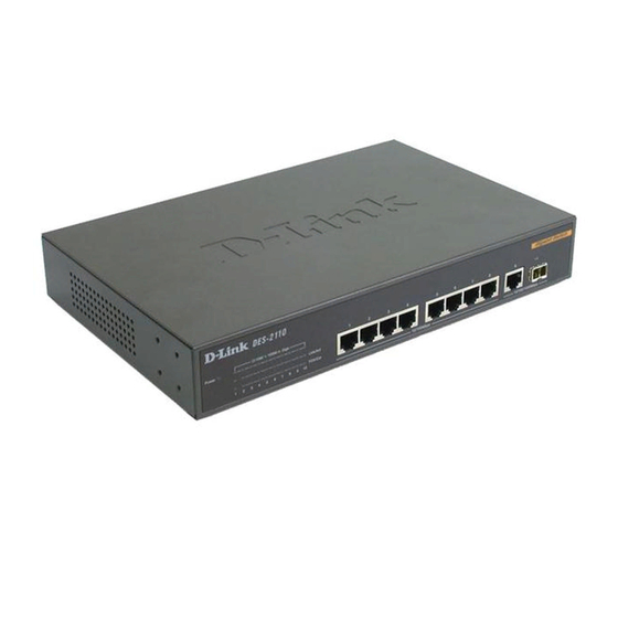
DENTIFYING XTERNAL OMPONENTS This chapter describes the front panel, rear panel and LED indicators of the Switch Front Panel Components The front panel of the Switch consists of eight (8) 10/100Mbps Fast Ethernet ports, one (1) 10/100/1000Mbps Gigabit Ethernet port, one (1) mini-GBIC port, LED indicators and Reset button. -
Page 22: Rear Panel
Rear Panel The rear panel of the Switch contains an AC power connector. Figure 5. Rear panel view The AC power connector is a standard three-pronged connector that supports the power cord. Plug-in the female connector of the provided power cord into this socket, and the male side of the cord into a power outlet. -
Page 23: Power And Cpu Leds
Power and CPU LEDs Power : This LED will light green after the Switch is powered on to indicate the ready state of the device. : When the switch powered off or the power cord has improper connection. : When the CPU is working, the CPU LED is blinking. Blinking : The CPU is not working. -
Page 24: Port 9, Gigabit Ethernet Port Status Leds
Port 9, Gigabit Ethernet Port Status LEDs Link/Act : When the Link/Act LED lights on, the respective port is successfully connected to an Ethernet network. Blinking : When the Link/Act LED is blinking, the port is transmitting or receiving data on the Ethernet network. : No link. -
Page 25: Introduction To Switch Management
NTRODUCTION WITCH ANAGEMENT Management Options Web Management Utility Web-based Management Interface Command Line Interface (CLI) SNMP-Based Management Managing Management Options This system may be managed in-band using TCP/IP Telnet protocol and web-based management, accessible through a web browser. Web Management Utility With the Web Management Utility, you can easily discover all the Web Management Switch, assign the IP Address, changing the password and upgrading the new firmware. -
Page 26: Command Line Interface (Cli)
Command Line Interface (CLI) The Switch supports a Command Line Interface (CLI) that allows the user to connect to the Switch’s management agent using the TCP/IP Telnet protocol. SNMP-Based Management You can manage the Switch with an SNMP-compatible console program. The Switch supports SNMP version 1.0. The SNMP agent decodes the incoming SNMP messages and responds to requests with MIB objects stored in the database. -
Page 27: Configuration The Switch
ONFIGURATION WITCH Through the Web Browser, Telnet and SNMP you can configure the Switch such as Port setting, VLAN, QoS, SNMP, Spanning Tree… etc. Web Management Utility With the attached Web Management Utility, you can easily discover all the Web Management Switch, assign the IP Address, changing the password and upgrading the new firmware. -
Page 28: Discovery List
Figure 7. Web Management Utility The Web Management Utility was divided into four parts, Discovery List, Monitor List, Device Setting and Toolbar function, for details instruction, follow the below section. Discovery List This is the list where you can discover all the Web management devices in the entire network. -
Page 29: Monitor List
System word definitions in the Discovery List: MAC Address: Shows the device MAC Address. IP Address: Shows the current IP address of the device. Protocol version: Shows the version of the Utility protocol. Product Name: Shows the device product name. System Name: Shows the appointed device system name. - Page 30 View Trap: The Trap function can receive the events that happen from the Web Management Switch in the Monitor List. There is a light indicator behind the “View Trap” button, when the light indicates in green, it means that there is no trap transmitted, and else when it indicates in red, it means that there is new trap transmitted, this is to remind us to view the trap.
-
Page 31: Device Setting
In factory default, the IP address of the DES-2110 will atomically assign from DHCP server (DHCP enabled). If your network has no DHCP server, the DES-2110 will fail to get IP address, and the IP address of DES-2110 will be assigned to default IP address of 192.168.0.1 and netmask is 255.255.255.0. -
Page 32: Firmware Upgrade
Figure 10. Configuration Setting Password Change: You can use this Password Change when you need to change the password, fill in the password needed in the dialog box and press “Set” button to precede the password change immediately. Figure 11. Password Change Firmware Upgrade: When the device has a new function, there will be a new firmware to update the device, use this function to update. -
Page 33: Toolbar
Figure 12. Firmware Upgrade Web Access: Double click the device in the Monitor List or select a device in the Monitor List and press this “Web Access” button to access the device in Web browser. Toolbar The toolbar in the Web Management Utility have four main tabs, File, View, Options and Help. -
Page 34: Configuring The Switch Using Web Browser
Web Management Utility. Configuring the Switch using Web Browser All software functions of the DES-2110 can be managed, configured and monitored via the embedded web-based (HTML) interface. The Switch can be managed from remote stations anywhere on the network through a standard browser such as Netscape Navigator or Microsoft Internet Explorer. -
Page 35: Login To Web Manager
web-based management are the same as those found in the console program. The section indicates how to manage, control and monitor the Switch via Web Browser. The Switch to enable its managed functions including: Port Setting Virtual LAN Group setting, Port-based or 802.1Q-based Port Mirroring Spanning Tree SNMP... - Page 36 Figure 13. Or through the Web Management Utility, you do not need to remember the IP Address, select the device shown in the Monitor List of the Web Management Utility to settle the device on the Web Browser. When the following dialog page appears, remain enter the default password "admin"...
- Page 37 Figure 15. Device Status...
-
Page 38: Setup Menu
Setup Menu When the main page appears, find the Setup menu in the left side of the screen (Figure 16). Click on the setup item that you want to configure. There are fifteen options: Port Settings, VLAN Settings, Mirror Setting, Spanning Tree Settings, SNMP Settings, Static MAC Settings, IGMP Snooping Settings, Device Status, Statistic, System Settings, Trap Setting, Password Setting, Backup Setting and Reset Setting as shown in the Main Menu screen. -
Page 39: Configuring Setup Setting
Configuring Setup Setting Find that there are four items, including Port Settings, VLAN Settings, Mirror Settings, Spanning Tree, SNMP, Static MAC and IGMP Snooping in Setup menu. Port Settings In Port Settings menu (Figure 17), this page will show each port’s status, press the ID parameter to set each port’s Speed, Flow Control, QoS priority and Link Status. - Page 40 To change the port setting, click on the ID parameter to enter to the selected port to configure its Speed/Disable, Flow control and QoS setting. Figure 18. Speed: Port 1~9: This setting has six modes -- 100M Full, 100M Half, 10M Full, 10M Half, Auto and Disable for speed or port disable selections.
-
Page 41: Vlan Settings (Virtual Local Area Network)
VLAN Settings (Virtual Local Area Network) The DES-2110 supports two of VLAN type: Port-Based VLAM or IEEE 802.1Q-Based VLAN. The VLAN setting only working on one of the two VLAN types, the default VLAN setting is Port-Based VLAN type, if you change to the other VLAN mode, the current VLAN setting will be erased. - Page 42 Once you want to modify the VLAN Group, check on the ID parameter, the ID VLAN configuration window will pop out. Figure 21. Port_based VLAN Settings IEEE 802.1Q VLAN: VID Table Setting: select the VID group that you set. When you select VID Table Setting, press “Add new VID” to create new VID group, from port 01 ~ port 10, select Untag Port, Tag Port or Not Member for each port.
- Page 43 Port VID Setting: When you select Port VLAN setting, fill in each port’s PVID value between 1 and 4094. Figure 23. 802.1Q Port VID Setting Note: If you change the VLAN mode to the other VLAN mode, the current VLAN setting will be erased. Figure 24.
-
Page 44: Mirror Setting
Mirror Setting Port Mirroring is a method of monitoring network traffic that forwards a copy of each incoming and/or outgoing packet from one port of a network switch to another port where the packet can be studied. It enables the manager to keep close track of switch performance and alter it if necessary. -
Page 45: Spanning Tree Setting
Spanning Tree Setting This Switch supports the 802.1d Spanning Tree Protocol. Every segment will have a single path to the root bridge. All bridges listen for BPDU packets. However, BPDU packets are sent more frequently - with every Hello packet. BPDU packets are sent even if a BPDU packet was not received. - Page 46 the network, preventing the effective propagation of the new information. Set by the Root Bridge, this value will aid in determining that the Switch has spanning tree configuration values consistent with other devices on the bridged LAN. If the value ages out and a BPDU has still not been received from the Root Bridge, the Switch will start sending its own BPDU to all other switches for permission to become the Root Bridge.
-
Page 47: Snmp Setting
MIB specifications and the protocol used to access this information over the network. The DES-2110 supports the SNMP versions 1. In SNMP v.1, user authentication is accomplished using 'community strings', which function like passwords. The remote user SNMP application and the Switch SNMP must use the same community string. - Page 48 Traps Traps are messages that alert network personnel of events that occur on the Switch. The events can be as serious as a reboot (someone accidentally turned OFF the Switch), or less serious like a port status change. The Switch generates traps and sends them to the trap recipient (or network manager).
- Page 49 MIBs Management and counter information are stored by the Switch in the Management Information Base (MIB). The Switch uses the standard MIB-II Management Information Base module. Consequently, values for MIB objects can be retrieved from any SNMP-based network management software. In addition to the standard MIB-II, the Switch also supports its own proprietary enterprise MIB as an extended Management Information Base.
- Page 50 Add Group: To add a SNMP Community group, press “Add Group” button, the Add SNMP Community configuration window will pop out; fill in the community name and assign the community enable read_only or read_write. Press “Apply” button to execute the setting. Figure 28.
- Page 51 Modify Group: To modify previously defined SNMP Community group, click on the ID parameter to enter to the selected SNMP Community Group to configure its community name and community enable. Press “Apply” to save change of the SNMP Community Group. Figure 30.
- Page 52 Add Trap: To create a recipient of SNMP traps generated by the Switch’s SNMP agent, press “Add Trap” button, and the SNMP Trap Set window will pop out; you can fill in the community name and trap IP address of the remote management station that will serve as the SNMP host for the Switch and checked the events selection to enabled selected event traps.
-
Page 53: Static Mac
Modify Trap: To modify previously defined SNMP Trap, click on the ID parameter to enter to the selected SNMP Trap to configure its community name, IP address and events. Press “Apply” to save change of the SNMP Trap. Figure 34. Modify SNMP Trap Static MAC The Static MAC function allows you to enable the Switch to forward the data packets to specific MAC address and specific port. - Page 54 excluding uplink port” setting), and the Switch will forward data following the Static MAC Address Table to the specific port. Select “Disabled”, the Switch will learn and build MAC address table automatically and the Switch will forward data following the auto learning MAC Address Table to the specific port.
-
Page 55: Igmp Snooping Setting
Remove Static MAC rule: Press “Delete Mac” button, and the Static MAC Delete window will pop out; checked the dialog box. Press “Apply” to delete the selected Static MAC rule from the list. Figure 37. Delete Static MAC IGMP Snooping Setting IGMP Snooping allows the Switch to read the Multicast Group IP address and the corresponding MAC address from IGMP packets that pass through the Switch. - Page 56 Enabled / Disabled: To selecting enable or disable IGMP Snooping function on the Switch. IGS Configure & Router Ports / Mcast table: To selecting of configure the IGMP Snooping or view the Multicast Entry Table. Host Timeout (1-16711450): Specifies the maximum amount of time a host can be a member of a multicast group without the Switch receiving a host membership report.
-
Page 57: Device Status
Device Status Click on the “Status” to present the device status on this screen, it will show the System Status, Port Status, VLAN Setting, Mirror Setting, Spanning Tree status, SNMP Setting and IGMP Setting. Figure 39. Device Status. Press “Refresh” when you need to renew the posted information. -
Page 58: Statistic
Statistic The Statistic Menu screen will show the status of each port packet count. Figure 40. Device Statistics For Detail packet information, click on the ID parameter as Figure 42. Figure 41. Port Statistics... -
Page 59: System Setting
System Setting The System Setting includes the System name, Location name, Login Timeout, IP Address, Subnet Mask and Gateway. Through the Web Management Utility, you can easily recognize the device by using the System Name and the Location Name. The Login Timeout is to set the idle time-out for security issue, when there is no action when running the Web Smart Utility and the time is up, you must re-login to Web Smart Utility before you set the Utility. -
Page 60: Trap Setting
Trap Setting The Trap Setting enables the device to monitor the Trap through the Web Management Utility, set the Trap IP Address of the manager where the trap to be sent. Figure 43. Trap Setting System Events: Monitoring the system’s trap. Device Bootup: a trap when booting up the system. -
Page 61: Set Password
Copper Port Events: Monitoring the copper port status. Abnormal* Receive Error: a trap when there are receive data error in copper port. Abnormal* Transmit Error: a trap when there are transmit data error in copper port. Abnormal*: 50 error packet count within 10 seconds. Set Password Password is the invaluable tool for the manager to secure Web Management Switch, use this function to change the password. -
Page 62: Backup Setting
Backup Setting The backup tools help you to backup the current setting of the Switch. Once you need to backup the setting, press the “Backup” button to save the setting. To restore a current setting file to the device, you must specify the backup file and press “Restore”... -
Page 63: Logout
Logout When press this function, the web configuration will go back to first Login page. Figure 47. Logout... -
Page 64: Configuring The Switch Using The Cli
Configuring the Switch using the CLI The Switch can be managed through the TCP/IP Telnet protocol. The Command Line Interface (CLI) can be used to configure and manage the Switch via TCP/IP Telnet protocol. This section provides a reference for all of the commands contained in the CLI. -
Page 65: Using The Cli Via Telnet Interface
Where ip-address is the IP address you have assigned to the Switch. When you telnet to the Switch, it displays its login-in message: Figure 49. The DES-2110 console login At this point you can enter the password you have assigned to your print server. -
Page 66: Command Syntax
Figure 50. DES-2110 CLI command prompt Command Syntax The following symbols are used to describe how command entries are made and values and arguments are specified in this manual. The online help contained in the CLI and available through console interface uses the same syntax. - Page 67 | vertical bar Separates two or more mutually exclusive items Purpose in a list, one of which must be entered. Syntax show snmp [community | host] In the above syntax sample, you must specify Description either a community or host configuration to be show.
-
Page 68: Basic Switch Commands
Basic Switch Commands The basic switch commands in the Command Line Interface (CLI) are listed (along with the appropriate parameters) in the following table. Command Parameters show switch auto_logout <value 3 ~ 30> config system {<system_name >} config system_name {<location_name>} config location_name reset <config>... - Page 69 Example usage: To display the Switch’s information: Figure 51. show switch command config system Used to configure the auto log out timer of the Purpose Switch. Syntax config system auto_logout < value 3 ~ 30 > This command is used to configure the auto log Description out timer of the Switch.
- Page 70 Example usage: To configure the Switch will auto log out if there is no user input for 10 minutes. Figure 52. config system command config system_name Used to configure the name for the Switch. Purpose Syntax config system_name {<system_name>} The config system_name command configures Description the name of the Switch.
- Page 71 config location_name Used to enter a description of location of the Purpose Switch. Syntax config location_name {<location_name>} The command is used to enter a description of Description the location of the Switch. A maximum of 20 characters can be used. Parameters <location_name>...
- Page 72 Example usage: To restore all of the Switch’s parameters to their default values: Figure 55. reset command logout Used to log out a user from the Switch’s console. Purpose Syntax logout This command terminates the current session on Description the Switch’s console. None.
-
Page 73: Basic Ip Commands
save Used save changes Switch’s Purpose configuration to non-volatile RAM. Syntax save This command is used to enter the current switch Description configuration into non-volatile RAM. The saved switch configuration will be loaded into the Switch’s memory each time the Switch is restarted. - Page 74 Each command is listed, in detail, in the following sections. config ipif Used to configure the System IP interface. Purpose Syntax config ipif [ipaddress <network address> | {gw <ipaddress>} | dhcp {vid <vlan_id>}] This command is used to configure the System Description IP interface on the Switch.
-
Page 75: Switch Port Commands
show ipif Used to display the configuration of an IP Purpose interface on the Switch. Syntax show ipif This command will display the configuration of an Description IP interface of the Switch. None. Parameters Example usage: To display IP interface settings: Figure 59. - Page 76 Each command is listed, in detail, in the following sections. config ports Purpose Used to configure the Switch’s Ethernet port settings. Syntax [<portlist | all> {speed [disable |auto |10_half | 10_full | 100_half | 100_full | 1000_full} | {flow_control [enable | disable] | qos {normal | high]} Description This command allows for the configuration of the...
- Page 77 Figure 60. config ports command show ports Used to display current configuration of a range Purpose of ports. Syntax show ports {portlist} This command is used to display current Description configuration of a range of ports. Parameters <portlist> - Specifies a port or range of ports to be displayed.
- Page 78 Example usage: To display the configuration of all ports on the switch: Figure 61. show ports command...
-
Page 79: Vlan Commands
VLAN Commands The VLAN commands in the Command Line Interface (CLI) are listed (along with the appropriate parameters) in the following table. Command Parameters [<vlan_name 8> | tag <vlanid create vlan 1~4094>] <vlan_name 8> {tag <vlanid delete vlan 1~4094>} [<vlan_name 8> { tag <vlanid config vlan 1~4094>} [add... - Page 80 Parameters <vlan_name 8> - The name of Port_based VLAN to be created. A maximum of 8 characters can be used. <vlanid 1~4094> - The VLAN ID of the 802.1Q_based VLAN to be created. Allowed values = 1~4094 Example usage: To create a Port_based VLAN, “sales” VLAN group: Figure 62.
-
Page 81: Example Usage
delete vlan Used to delete a previously configured VLAN on the Purpose Switch. Syntax delete vlan [<vlan_name 8> | tag <vlanid 1~4094>] This command will delete a previously configured VLAN Description on the Switch Parameters <vlan_name 8> - The VLAN name of the Port_based VLAN you want to delete. - Page 82 config vlan Used additional ports previously Purpose configured VLAN. Syntax config vlan [<vlan_name 8> | tag <vlanid 1~4094> add {tagged | untagged} | delete <portlist>] This command allows you to add ports to the port Description list of previously configured VLAN. Parameters <vlan_name 8>...
- Page 83 To delete 4 through 6 ports from the “sales” VLAN group: Figure 67. config vlan command, delete VLAN group members (port_based VLAN) To add 1 through 3 as tagged ports to the VLAN tag 10: Figure 68. config vlan command, add VLAN group members (802.1q_based VLAN) To delete port 3 from the VLAN tag 10: Figure 69.
- Page 84 enable port_based vlan Used to change the VLAN type to Port_based Purpose VLAN type on the Switch. Syntax enable port_based vlan This command allows you to change the VLAN Description type to Port_based VLAN on the Switch. None. Parameters Example usage: To switched the VLAN type to Port_based VLAN Figure 70.
- Page 85 Example usage: To switched the VLAN type to 802.1Q_based VLAN Figure 71. disable port_based vlan command enable 802.1q_based vlan Used to change the VLAN type to 802.1Q_based Purpose VLAN on the Switch. Syntax enable 802.1q_based vlan This command allows you to change the VLAN Description type to 802.1Q_based VLAN on the Switch.
- Page 86 disable 802.1q_based vlan Used to change the VLAN type to port_based Purpose VLAN on the Switch. Syntax disable 802.1q_based vlan This command allows you to change the VLAN Description type to port_based VLAN on the Switch. None. Parameters Example usage: To switched the VLAN type to Port_based VLAN Figure 73.
-
Page 87: Port Mirroring Commands
VLAN ID to the specified ports. priority <0~7> - To configure the priority to the specified PVID. Example usage: To configure the 802.1Q Port VLAN_ID: Figure 74. config pvid command Port Mirroring Commands The port mirroring commands in the Command Line Interface (CLI) are listed (along with the appropriate parameters) in the following table. - Page 88 Each command is listed, in detail, in the following sections. config mirror port Purpose Used to configure a mirror port – source port pair on the Switch. Traffic for any source port to a target port can be mirrored for real-time analysis. Syntax [enable | disable] {<port>...
- Page 89 Example usage: To enable and configure the Port Mirror function of the Switch: Figure 75. config mirror port command To disable Port Mirror function of the Switch: Figure 76. config mirror port command, disable port mirror function show mirror Used to show the current mirroring configuration Purpose on the Switch.
-
Page 90: Trap Commands
Example usage: To display port mirroring configuration: Figure 77. show mirror command Trap Commands The trap mirroring commands in the Command Line Interface (CLI) are listed (along with the appropriate parameters) in the following table. Command Parameters ipaddress <ip_address> {vid config discovery <vlan_id>} trap_ip... - Page 91 Each command is listed, in detail, in the following sections. config discovery trap_ip Purpose Used to configure an IP address of the trap recipient of Web Management Utility to the Switch. Syntax config discovery trap_ip ipaddress <ip_address> {vid <vlan_id>} The command is configure an IP address of the Description trap recipient of Web Management Utility to the Switch.
- Page 92 config discovery trap_event Used to configure the events of the trap on the Purpose Switch. Syntax config discovery trap_event {[bootup | illegal_login | t_rx_err | t_tx_err | f_rx_err | f_tx_err | f_link_change]} The command is configure the events of the trap Description on the Switch..
- Page 93 Example usage: To configure the events type of the Switch: Figure 79. config discovery trap_event command delete discovery trap_event Purpose Used to delete previously configured events of trap on the Switch. Syntax delete discovery trap_event {[bootup | illegal_login | t_rx_err | t_tx_err | f_rx_rtt | f_tx_err | f_link_change]} Description The command is delete previously configured...
- Page 94 delete discovery trap_event Parameters bootup - Disable the Switch’s boot up event. illegal_login - Disable the Switch’s illegal login event. t_rx_err - Disabled the Switch’s twisted-pair ports (port 1 – 9) error receive data packets event. t_tx_err - Disabled the Switch’s twisted-pair ports (port 1 –...
-
Page 95: Spanning Tree Commands
show discovery trap Used to show the configuration of the discovery Purpose trap on the Switch. Syntax show discovery trap The command is display the configuration of the Description discovery trap on the Switch.. None. Parameters Example usage: To display discovery trap configuration: Figure 81. - Page 96 Command Parameters enable stp disable stp {maxage <value 6-40> | hellotime config stp <value 1-10> | forwarddelay <4-30> | priority <value 1-65535> | fbpdu [enable | disable]} config stp ports [all | <portlist>] {cost <value 1- 65535> | priority <value 0-255>} show stp show stp ports <portlist>...
- Page 97 disable stp Used to disable STP on the Switch. Purpose Syntax disable stp This command allows the Spanning Tree Description Protocol to be disabled on the Switch. None. Parameters Example usage: To disable STP on the Switch: Figure 83. disable stp command config stp Purpose Used to setup STP on the Switch.
- Page 98 config stp devices on the bridged LAN. If the value ages out Parameters and a BPDU has still not been received from the Root Bridge, the Switch will sending its own BPDU to all other switches for permission become the Root Bridge. If it turns on that your switch has the lowest Bridge identifier, it will become the Root Bridge.
- Page 99 Example usage: To configure STP with maxage 40 and hellotime of 5 seconds: Figure 84. config stp command config stp ports Used to setup STP on the port level. Purpose Syntax config stp ports [all | <portlist>] {cost <value 1-65535> | priority <value 0-255>} This command is used to create and configure Description STP for a group of ports.
- Page 100 Example usage: To configure STP with path cost 10, priority of 100 for ports 1-5: Figure 85. config stp ports command show stp Purpose Used to display the Switch’s current STP configuration. Syntax show stp This command displays the Switch’s current STP Description configuration.
- Page 101 Example usage: To display the status of STP on the Switch: Figure 86. show stp command show stp ports Used to display the Switch’s current STP group Purpose of ports configuration on the Switch. Syntax show stp ports {portlist} This command displays the STP group of Description configuration on the Switch.
- Page 102 Example usage: To display the STP status of port on the Switch: Figure 87. show stp ports command...
-
Page 103: Snmp Commands
SNMP Commands The SNMP commands in the Command Line Interface (CLI) are listed (along with the appropriate parameters) in the following table. Command Parameters <community_string 20> [read_only | create snmp read_write] community delete snmp <community_string 20> [read_only | read_write] community show snmp <ipaddress>... - Page 104 create snmp community This command is used to create an SNMP Description community string and to assign access-limiting characteristics to this community string. Parameters <community_string 20> - An alphanumeric string of up to 20 characters that is used to identify members of an SNMP community. This string is used like a password to give remote SNMP managers access to MIB objects in the Switch’s SNMP agent.
- Page 105 delete snmp community Used to remove a specific SNMP community Purpose string from the Switch. Syntax delete snmp community <community_string 20> [ read_only | read_write ] Description This command is used to remove a previously defined SNMP community string from the Switch. Parameters <community_string 20>...
- Page 106 Used to display SNMP community strings Purpose configured on the Switch. Syntax show snmp community This command is used to display SNMP Description community strings that are configured on the Switch. Example usage: To display the currently entered SNMP community strings: Figure 90.
- Page 107 Parameters <ipaddress> - The IP address of the remote management station that will serve as the SNMP host for the Switch. <vlan_id> - Specific the 802.1Q VLAN ID of the SNMP recipient host. The range is between 1 to 4094. trap_community <community_string>...
- Page 108 Example usage: To display the currently configured SNMP hosts on the Switch: Figure 92. show snmp host command enable snmp traps Used to enable SNMP trap support on the Purpose Switch. Syntax enable snmp traps This command is used to enable SNMP trap Description support on the Switch.
- Page 109 Figure 93. enable snmp traps command disable snmp traps Used to disable SNMP trap support on the Purpose Switch. Syntax disable snmp traps Description This command is used to disable SNMP trap support on the Switch. None. Parameters Example usage: To disable SNMP trap support on the Switch: Figure 94.
-
Page 110: Igmp Snooping Commands
IGMP Snooping Commands The IGMP Snooping commands in the Command Line Interface (CLI) are listed (along with the appropriate parameters) in the following table. Command Parameters config router_ports [add | delete] <portlist> enable igmp snooping disable igmp snooping show router ports show igmp_snooping group config igmp_snooping... - Page 111 Example usage: To set up static router ports: Figure 95. config router_ports command (add static router ports) To delete static router ports: Figure 96. config router_ports command (delete static router ports) enable igmp snooping Used to enable IGMP snooping on the Switch. Purpose Syntax enable igmp snooping {forward_mcrouter_only}...
- Page 112 Example usage: To enable IGMP snooping on the Switch: Figure 97. enable igmp snooping command disable igmp snooping Used to disable IGMP snooping on the Switch. Purpose Syntax disable igmp snooping Description This command disables IGMP snooping on the Switch. None.
- Page 113 show router_ports Used to display the currently configured router Purpose ports on the Switch. Syntax show router_ports This command is used to display the currently Description configured router ports on the Switch. None. Parameters Example usage: To display the router ports: Figure 99.
- Page 114 Example usage: To view the current IGMP snooping group: Figure 100. show igmp_snooping command config igmp_snooping Used to configure IGMP snooping on the Switch. Purpose Syntax config igmp_snooping [host_timeout <sec 1- 16711450> | router_timeout <sec 1- 16711450>] This command allows you to configure IGMP Description snooping on the Switch.
- Page 115 Example usage: To configure IGMP snooping: Figure 101. config igmp_snooping command...
-
Page 116: Technical Specifications
ECHNICAL PECIFICATIONS General IEEE 802.3 10BASE-T Ethernet IEEE 802.3u 100BASE-TX Fast Ethernet IEEE 802.3ab 1000BASE-T Gigabit Ethernet Standards: ANSI/IEEE 802.3 Auto-negotiation IEEE 802.3x Full duplex Flow Control Protocol: CSMA/CD Ethernet: 10Mbps (half-duplex), 20Mbps (full-duplex) Data Fast Ethernet: 100Mbps (half-duplex), 200Mbps (full-duplex) Transfer Gigabit Ethernet: 2000Mbps (full-duplex) Rate:... -
Page 117: Physical And Environmental
Physical and Environmental 100-240 VAC, 50-60 Hz AC inputs: 9 watts maximum Power Consumption: Operating 0 ~ 40 degrees Celsius Temperature: -10 ~ 70 degree Celsius Storage Temperature: Humidity: 10% ~ 90% RH, non-condensing Dimensions: 280 mm x 180 mm x 44 mm EMI: FCC Class A, CE Mark Class A, VCCI Class A Performance... -
Page 118: All Countries And Regions Excluding Usa
A R R A N T Y A N D E G I S T R A T I O N N F O R M A T I O N (All countries and regions excluding USA) Wichtige Sicherheitshinweise Bitte lesen Sie sich diese Hinweise sorgfältig durch. Heben Sie diese Anleitung für den spätern Gebrauch auf. - Page 119 12. Wird das Gerät über einen längeren Zeitraum nicht benutzt, sollten Sie es vom Stromnetz trennen. Somit wird im Falle einer Überspannung eine Beschädigung vermieden. 13. Durch die Lüftungsöffnungen dürfen niemals Gegenstände oder Flüssigkeiten in das Gerät gelangen. Dies könnte einen Brand bzw. Elektrischen Schlag auslösen.
- Page 120 WITH THE SALE, INSTALLATION MAINTENANCE OR USE OF D-LINK'S PRODUCTS. D-LINK SHALL NOT BE LIABLE UNDER THIS WARRANTY IF ITS TESTING AND EXAMINATION DISCLOSE THAT THE ALLEGED DEFECT IN THE PRODUCT DOES NOT EXIST OR WAS CAUSED BY THE CUSTOMER'S OR...
- Page 121 This Warranty applies on the condition that the product Registration Card is filled out and returned to a D-Link office within ninety (90) days of purchase. A list of D-Link offices is provided at the back of this manual, together with a copy of the Registration Card.
- Page 122 Registration Card. If a Registration Card for the product in question has not been returned to a D-Link office, then a proof of purchase (such as a copy of the dated purchase invoice) must be provided when requesting warranty service.
- Page 123 D-Link's obligation under this warranty shall be a reasonable effort to provide compatibility, but D-Link shall have no obligation to provide compatibility when there is fault in the third-party hardware or software. D-Link makes no warranty that operation of its software products will be uninterrupted or absolutely error-free, and no warranty that all defects in the software product, within or without the scope of D-Link's applicable product documentation, will be corrected.
- Page 124 1000 or more 3. What network protocol(s) does your organization use ? XNS/IPX TCP/IP DECnet Others_____________________________ 4. What network operating system(s) does your organization use ? D-Link LANsmart Novell NetWare NetWare Lite SCO Unix/Xenix PC NFS 3Com 3+Open Banyan Vines...
- Page 125 Retail/Chainstore/Wholesale Government Transportation/Utilities/Communication System house/company Other________________________________ 9. Would you recommend your D-Link product to a friend? Don't know yet 10.Your comments on this product? _____________________________________________________________________________...