Lenovo x3550 M4 Installation And Service Manual
Hide thumbs
Also See for x3550 M4:
- Installation and service manual (1006 pages) ,
- Product manual (44 pages) ,
- Product manual (43 pages)
Table of Contents
Advertisement
Quick Links
Advertisement
Table of Contents
Troubleshooting

Related Manuals for Lenovo x3550 M4


Summary of Contents for Lenovo x3550 M4
- Page 1 System x3550 M4 Type 7914 Installation and Service Guide...
- Page 3 System x3550 M4 Type 7914 Installation and Service Guide...
- Page 4 Environmental Notices and User Guide documents on the IBM Documentation CD. Nineteenth Edition (June 2015) © Copyright Lenovo 2012, 2015. LIMITED AND RESTRICTED RIGHTS NOTICE: If data or software is delivered pursuant a General Services Administration “GSA” contract, use, reproduction, or disclosure is subject to restrictions set forth in Contract No.
-
Page 5: Table Of Contents
Installing a USB embedded hypervisor flash device Safety statements . Installing an additional microprocessor and heat sink . . 81 Chapter 1. The System x3550 M4 server Thermal grease . . 88 The Documentation CD. Installing a SAS/SATA 4 Pac HDD option . - Page 6 How to send DSA data . . 598 Chapter 5. Parts listing, Lenovo Creating a personalized support web page . 599 System x3550 M4 Type 7914 ..179 Software service and support . . 599 Hardware service and support . 599 Replaceable server components .
- Page 7 People's Republic of China Class A electronic Index ....609 emission statement . 607 Taiwan Class A compliance statement . . 607 Contents...
- Page 8 System x3550 M4 Type 7914: Installation and Service Guide...
-
Page 9: Safety
Ennen kuin asennat tämän tuotteen, lue turvaohjeet kohdasta Safety Information. Avant d'installer ce produit, lisez les consignes de sécurité. Vor der Installation dieses Produkts die Sicherheitshinweise lesen. Prima di installare questo prodotto, leggere le Informazioni sulla Sicurezza. © Copyright Lenovo 2012, 2015... -
Page 10: Guidelines For Trained Service Technicians
Use good judgment to identify potential unsafe conditions that might be caused by unsupported alterations or attachment of unsupported features or optional devices that are not addressed in this section. If viii System x3550 M4 Type 7914: Installation and Service Guide... -
Page 11: Guidelines For Servicing Electrical Equipment
you identify an unsafe condition, you must determine how serious the hazard is and whether you must correct the problem before you work on the product. Consider the following conditions and the safety hazards that they present: v Electrical hazards, especially primary power. Primary voltage on the frame can cause serious or fatal electrical shock. -
Page 12: Safety Statements
Be sure to read all caution and danger statements in this documentation before you perform the procedures. Read any additional safety information that comes with your system or optional device before you install the device. Statement 1 System x3550 M4 Type 7914: Installation and Service Guide... - Page 13 DANGER Electrical current from power, telephone, and communication cables is hazardous. To avoid a shock hazard: v Do not connect or disconnect any cables or perform installation, maintenance, or reconfiguration of this product during an electrical storm. v Connect all power cords to a properly wired and grounded electrical outlet. v Connect to properly wired outlets any equipment that will be attached to this product.
- Page 14 Luokan 1 Laserlaite Appareil A Laser de Classe 1 Statement 4 CAUTION: Use safe practices when lifting. ≥ 18 kg (39.7 lb) ≥ 32 kg (70.5 lb) ≥ 55 kg (121.2 lb) System x3550 M4 Type 7914: Installation and Service Guide...
- Page 15 Statement 5 CAUTION: The power control button on the device and the power switch on the power supply do not turn off the electrical current supplied to the device. The device also might have more than one power cord. To remove all electrical current from the device, ensure that all power cords are disconnected from the power source.
- Page 16 The following label indicates a hot surface nearby. Statement 26 CAUTION: Do not place any object on top of rack-mounted devices. Statement 27 CAUTION: Hazardous moving parts are nearby. Rack Safety Information, Statement 2 System x3550 M4 Type 7914: Installation and Service Guide...
- Page 17 DANGER v Always lower the leveling pads on the rack cabinet. v Always install stabilizer brackets on the rack cabinet. v Always install servers and optional devices starting from the bottom of the rack cabinet. v Always install the heaviest devices in the bottom of the rack cabinet. Safety...
- Page 18 System x3550 M4 Type 7914: Installation and Service Guide...
-
Page 19: Chapter 1. The System X3550 M4 Server
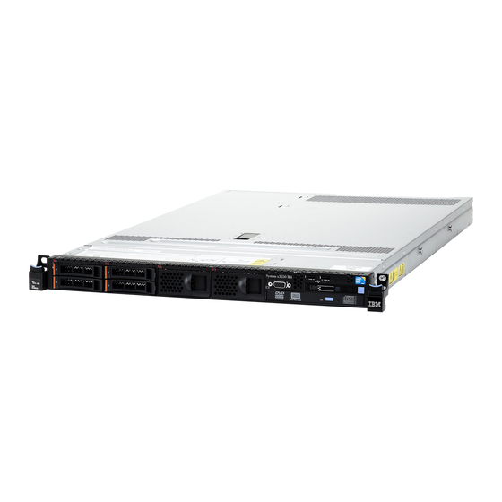
Chapter 1. The System x3550 M4 server This publication contains information and instructions for setting up your System x3550 M4 server, instructions for installing some optional devices, cabling and configuring the server, removing and replacing devices, and diagnostics and troubleshooting information. - Page 20 Machine type 7914 Model number _____________________________________________ Serial number _____________________________________________ The model number and serial number are on the ID label on the front of the server, as shown in the following illustration. System x3550 M4 Type 7914: Installation and Service Guide...
-
Page 21: The Documentation Cd
Hardware and software requirements The Documentation CD requires the following minimum hardware and software: v Microsoft Windows XP, Windows 2000, or Red Hat Linux v 100 MHz microprocessor v 32 MB of RAM Chapter 1. The System x3550 M4 server... -
Page 22: Using The Documentation Browser
The following documentation also comes with the server: v Environmental Notices and User Guide System x3550 M4 Type 7914: Installation and Service Guide... - Page 23 Warranty Information This document is in printed format and comes with the server. It contains warranty terms and a pointer to the Lenovo Statement of Limited Warranty on the website. Depending on the server model, additional documentation might be included on the Documentation CD.
-
Page 24: Notices And Statements In This Document
Server features and specifications The following information is a summary of the features and specifications of the server. Depending on the model, some features might not be available, or some specifications might not apply. System x3550 M4 Type 7914: Installation and Service Guide... - Page 25 Slot 1 supports low-profile cards. – PCI Express 3.0 x16 v Slot 2 supports half-length, full-height cards. – PCI Express 3.0 x8 – PCI Express 3.0 x16 (two microprocessors installed) – PCI-X 64-bit/133 MHz Chapter 1. The System x3550 M4 server...
- Page 26 – RAID 5/50 (512 MB Flash) with optional FoD RAID 6/60 and SED upgrade – RAID 5/50 (1 GB Flash) with optional FoD RAID 6/60 and SED upgrade – RAID 5/50 and SED (Zero Cache) System x3550 M4 Type 7914: Installation and Service Guide...
- Page 27 Maximum dew point: 29°C (84.2°F) v Sound power, idling: 6.5 bels maximum v Sound power, operating: 6.5 bels maximum EU Regulation 617/2013 Technical Documentation: International Business Machines Corporation New Orchard Road Armonk, New York 10504 Chapter 1. The System x3550 M4 server...
-
Page 28: What Your Server Offers
Generalized Test Protocol for Calculating the Energy Efficiency of Internal Ac-Dc and Dc-Dc Power Supplies. What your server offers This section introduces features and technologies the server uses and provides. v Active Energy Manager System x3550 M4 Type 7914: Installation and Service Guide... - Page 29 (as the IPMI event log), the integrated management module (IMM) event log (as the ASM event log), and the operating-system event logs. You can send the DSA log as a file to Lenovo Support or view the information as a text file or HTML file.
- Page 30 Service Information website provides additional information for parts installation and replacement videos, and error codes for server support. For the QR code, see QR code information on page Chapter 1, “The System x3550 M4 server,” on page 1. v Multi-core processing The server supports up to two multi-core microprocessors.
- Page 31 Note: The server does not support DOS (Disk Operating System). v VMware ESXi embedded hypervisor An optional USB flash device with VMware ESXi embedded hypervisor software is available for purchase. Hypervisor is virtualization software that enables Chapter 1. The System x3550 M4 server...
-
Page 32: Reliability, Availability, And Serviceability
Parity checking on the small computer system interface (SCSI) bus and PCI-E and PCI/PCI-X buses v Power management: Compliance with Advanced Configuration and Power Interface (ACPI) v Power-on self-test (POST) System x3550 M4 Type 7914: Installation and Service Guide... -
Page 33: Ibm Systems Director
Monitoring v Updates v Event notification v Automation for managed systems The IBM Systems Director Web and command-line interfaces provide a consistent interface that is focused on driving these common tasks and capabilities: Chapter 1. The System x3550 M4 server... -
Page 34: Server Controls, Leds, And Power
The following illustrations show the controls, LEDs, and connectors on the front of your server model. 2.5-inch hard disk drive server model. Figure 5. Front view: 2.5-inch 3.5-inch hard disk drive server model. System x3550 M4 Type 7914: Installation and Service Guide... -
Page 35: Operator Information Panel
USB connectors: Connect a USB device, such as a USB mouse or keyboard to any of these connectors. Operator information panel The following illustrations show the controls and LEDs on the advanced operator information panel and the operator information panel depending on your server model. Chapter 1. The System x3550 M4 server... - Page 36 This LED is controlled by the IMM. Notes: System x3550 M4 Type 7914: Installation and Service Guide...
-
Page 37: Light Path Diagnostics Panel
Figure 9. Light path diagnostics panel exposure The following illustration shows the LEDs and controls on the light path diagnostics panel. Chapter 1. The System x3550 M4 server... -
Page 38: Rear View
NMI button: Press this button to force a nonmaskable interrupt to the microprocessor. It allows you to blue screen the server and take a memory dump (use this button only when directed by the Lenovo service support). You System x3550 M4 Type 7914: Installation and Service Guide... - Page 39 IMM2 using either the Ethernet 1 or the system-management Ethernet (default) connector. The following illustration shows the LEDs on the rear of the server. Figure 12. Rear view LEDs The following illustration shows the LEDs on a dc power supply. Chapter 1. The System x3550 M4 server...
- Page 40 Flashing rapidly (4 times per second): The server is turned off and is not ready to be turned on. The power-control button is disabled. This will last approximately 5 to 10 seconds. System x3550 M4 Type 7914: Installation and Service Guide...
-
Page 41: Server Power Features
Use this information to turn off the server. When you turn off the server and leave it connected to power, the server can respond to requests to the service processor, such as a remote request to turn on Chapter 1. The System x3550 M4 server... - Page 42 PCI-X riser-card assembly. Otherwise, the Wake on LAN feature might not work. v The Integrated Management Module (IMM) can turn off the server as an automatic response to a critical system failure. System x3550 M4 Type 7914: Installation and Service Guide...
-
Page 43: Chapter 2. Installing Optional Devices
2. Shut down and restart the server multiple times to ensure that the server is correctly configured and functions correctly with the newly installed devices. 3. Save the DSA log as a file and send it to Lenovo. For information about transferring data and logs, see “How to send DSA data” on page 26. -
Page 44: How To Send Dsa Data
Secure upload with the system serial number: https://www.ecurep.ibm.com/ app/upload_hw Server components The following illustration shows the major components in the server. The illustrations in this document might differ slightly from your hardware. System x3550 M4 Type 7914: Installation and Service Guide... - Page 45 Figure 14. Server components Blue on a component indicates touch points, where you can grip the component to remove it from or install it in the server, open or close a latch, and so on. Orange on a component or an orange label on or near a component indicates that the component can be hot-swapped, which means that if the server and operating system support hot-swap capability, you can remove or install the component while the server is running.
-
Page 46: System-Board Internal Connectors
System-board internal connectors The following illustration shows the internal connectors on the system board. Figure 15. System-board internal connectors System-board external connectors The following illustration shows the external connectors on the system board. System x3550 M4 Type 7914: Installation and Service Guide... -
Page 47: System-Board Switches, Jumpers, And Buttons
Figure 16. System-board external connectors System-board switches, jumpers, and buttons The following illustration shows the location of the switches, jumpers, and buttons on the server. Important: 1. Before you change any switch settings or move any jumpers, turn off the server;... - Page 48 2 and 3 before the server is turned on alters which flash ROM page is loaded. Do not change the jumper pin position after the server is turned on. This can cause an unpredictable problem. System x3550 M4 Type 7914: Installation and Service Guide...
-
Page 49: System-Board Leds
You can also use it to force a blue-screen memory dump (use this button only when you are directed to do so by Lenovo Support). System-board LEDs The following illustration shows the light-emitting diodes (LEDs) on the system board. -
Page 50: System-Board Optional-Device Connectors
Figure 18. System-board LEDs System-board optional-device connectors The following illustration shows the connectors on the system board for the optional devices. System x3550 M4 Type 7914: Installation and Service Guide... -
Page 51: Installation Guidelines
Figure 19. System-board optional-device connectors Installation guidelines Use this information for installation. Attention: Static electricity that is released to internal server components when the server is powered-on might cause the system to halt, which might result in the loss of data. To avoid this potential problem, always use an electrostatic-discharge wrist strap or other grounding system when removing or installing a hot-swap device. -
Page 52: System Reliability Guidelines
When you are finished working on the server, reinstall all safety shields, guards, labels, and ground wires. System reliability guidelines To help ensure proper system cooling and system reliability, make sure that the following requirements are met. System x3550 M4 Type 7914: Installation and Service Guide... -
Page 53: Working Inside The Server With The Power On
v Each of the drive bays has a drive or a filler panel and electromagnetic compatibility (EMC) shield installed in it. v Each of the power-supply bays has a power supply or a filler installed in it. v If the server has redundant power, each of the power-supply bays has a power supply installed in it. -
Page 54: Handling Static-Sensitive Devices
4. Pull up firmly on the blue latch on the top (in the center of the front of the server) of the cover and slide the cover toward the rear of the server until the cover has disengaged from the chassis. System x3550 M4 Type 7914: Installation and Service Guide... -
Page 55: Removing The Air Baffle
Figure 20. Cover removal 5. Lift the server cover off the server and set it aside. Attention: For proper cooling and airflow, replace the server cover before you turn on the server. Removing the air baffle Use this information to remove the air baffle. About this task To remove the air baffle, complete the following steps: Procedure... -
Page 56: Installing Drives
The drive ID that is assigned to each drive is printed on the front of the server. The following illustrations show the locations of the IDs of the drives. The ID numbers and the drive bay numbers are the same. System x3550 M4 Type 7914: Installation and Service Guide... - Page 57 2.5-inch hot-swap hard disk drive IDs The hot-swap-drive ID that is assigned to each drive is printed on the front of the server. The following illustration shows the location of the IDs of the hard disk drives. The ID numbers and the drive bay numbers are the same. Figure 22.
-
Page 58: Installing Hot-Swap Hard Disk Drives
4. Install the hard disk drive in the drive bay: a. Make sure that the tray handle is in the open (unlocked) position. b. Align the drive with the guide rails in the bay. System x3550 M4 Type 7914: Installation and Service Guide... -
Page 59: Installing Simple-Swap Hard Disk Drives
Figure 26. Hot-swap hard disk drives installation c. Gently push the drive into the bay until the drive stops. d. Rotate the tray handle to the closed (locked) position. e. Check the hard disk drive status LED to verify that the hard disk drive is operating correctly. - Page 60 Gently push the drive into the bay until the drive stops. 6. Reinstall the drive bay filler panel that you removed earlier. 7. If you are installing additional simple-swap hard disk drives, do so now. System x3550 M4 Type 7914: Installation and Service Guide...
-
Page 61: Installing An Optional Dvd Drive
Results If you have other devices to install or remove, do so now. Otherwise, go to “Completing the installation” on page 92. Installing an optional DVD drive Use this information to install an optional DVD drive. About this task To install an optional DVD drive, complete the following steps: Procedure 1. - Page 62 7. Follow the instructions that come with the DVD drive to set any jumpers or switches. 8. Attach the drive retention clip that you removed from the DVD drive filler panel to the side of the new DVD drive. System x3550 M4 Type 7914: Installation and Service Guide...
- Page 63 Figure 30. DVD drive retention clip installation 9. Align the DVD drive in the drive bay and slide the DVD drive into the optical drive bay until the DVD drive clicks into place. Figure 31. DVD drive installation 10. Connect the DVD drive cable (see “Replacing the DVD drive cable” on page 226).
-
Page 64: Installing An Optional Dvd Drive Cable
4. Remove the air baffle (see “Removing the air baffle” on page 37). 5. Align the cable connector with the connector on the rear of the DVD drive cage. Press the cable connector into the optical drive cage connector and slide it System x3550 M4 Type 7914: Installation and Service Guide... - Page 65 to the left until it is firmly seated. Figure 33. DVD drive cable latch The following illustration shows cable routing for the DVD cable: Attention: Follow the optical drive cable routing as the illustration shows. Make sure that the cable is not pinched and does not cover any connectors or obstruct any components on the system board.
-
Page 66: Installing A Memory Module
– The specifications of a DDR3 DIMM are on a label on the DIMM, in the following format. ggggg eRxff PC3v-wwwwwm-aa-bb-ccd where: System x3550 M4 Type 7914: Installation and Service Guide... - Page 67 - ggggg is the total capacity of the DIMM (for example, 1 GB, 2 GB, or 4 GB) - eR is the number of ranks 1R = single-rank 2R = dual-rank 4R = quad-rank - xff is the device organization (bit width) x4 = x4 organization (4 DQ lines per SDRAM) x8 = x8 organization x16 = x16 organization...
- Page 68 A minimum of one DIMM must be installed for each microprocessor. For example, you must install a minimum of two DIMMs if the server has two microprocessors installed. However, to improve system performance, install a minimum of four DIMMs for each microprocessor. System x3550 M4 Type 7914: Installation and Service Guide...
-
Page 69: Dimm Installation Sequence
v DIMMs in the server must be the same type (RDIMM, UDIMM, or LRDIMM) to ensure that the server will operate correctly. v When you install one quad-rank DIMM in a channel, install it in the DIMM connector furthest away from the microprocessor. Notes: 1. -
Page 70: Memory Mirrored Channel
13, 16 Eighth pair of DIMMs 21, 24 Ninth pair of DIMMs 14, 17 Tenth pair of DIMMs 20, 23 Eleventh pair of DIMMs 15, 18 Twelfth pair of DIMMs 19, 22 System x3550 M4 Type 7914: Installation and Service Guide... -
Page 71: Memory Rank Sparing
Table 7. Memory mirrored channel mode DIMM population sequence (continued) Number of installed Number of DIMMs microprocessor DIMM connector Table note: DIMM connectors 3, 6, 7, 10, 15, 18, 19, and 22 are not used in memory mirrored channel mode when UDIMMs are installed in the server. Memory rank sparing The memory rank sparing feature disables the failed memory from the system configuration and activates a rank sparing DIMM to replace the failed active... -
Page 72: Installing A Memory Module
Note: If there is a gap between the DIMM and the retaining clips, the DIMM has not been correctly inserted; open the retaining clips, remove the DIMM, and then reinsert it. System x3550 M4 Type 7914: Installation and Service Guide... -
Page 73: Installing An Adapter
Results If you have other devices to install or remove, do so now. Otherwise, go to “Completing the installation” on page 92. Installing an adapter The following notes describe the types of adapters that the server supports and other information that you must consider when you install an adapter. About this task v Locate the documentation that comes with the adapter and follow those instructions in addition to the instructions in this section. - Page 74 System x Table note: 1. You can purchase System x3550 M4 Thermal Solution Kit (option part number 00Y7117) to acquire two additional fans for your server. v Any high-definition video-out connector or stereo connector on any add-on video adapter is not supported v The server does not support full-length, full-height PCI adapters or legacy 5V PCI adapters.
- Page 75 Table 11. PCI riser slots supported configurations Configuration 2 (Two PCI riser-card microprocessors slot number Configuration 1 installed) Configuration 3 Slot 1 PCI Express 3.0 (x16) PCI Express 3.0 (x16) PCI Express 3.0 (x16) card with a PCI Express card with a PCI Express card with a PCI Express riser card with a riser card with a...
- Page 76 8. Perform any configuration tasks that are required for the adapter. Results If you have other devices to install or remove, do so now. Otherwise, go to “Completing the installation” on page 92. System x3550 M4 Type 7914: Installation and Service Guide...
-
Page 77: Installing A Serveraid Sas/Sata Controller
Installing a ServeRAID SAS/SATA controller Use this information to install a ServeRAID SAS/SATA controller. About this task Note: For brevity, in this documentation the ServeRAID SAS/SATA controller is often referred to as the SAS/SATA adapter or the ServeRAID adapter. The ServeRAID SAS/SATA controller can be installed in the dedicated connector on the system board or PCI riser-card slots (see “System-board internal connectors”... - Page 78 Insert the SAS/SATA adapter into the PCI riser cards (see “Replacing an adapter” on page 241). Figure 42. Adapter installation 8. Route the backplane signal cables (see “Cabling backplane” on page 195). System x3550 M4 Type 7914: Installation and Service Guide...
- Page 79 Figure 43. ServeRAID adapter cable routing 9. Connect the signal cables to the SAS/SATA adapter: a. ServeRAID H1110 adapter: Take the signal cable that is attached to the drive backplane for drive bays 0 through 3 and connect it to the SAS/SATA connector on the ServeRAID adapter.
- Page 80 Note: When you restart the server, you are prompted to import the existing RAID configuration to the new ServeRAID adapter. If you have other devices to install or remove, do so now. Otherwise, go to “Completing the installation” on page 92. System x3550 M4 Type 7914: Installation and Service Guide...
-
Page 81: Installing The Serveraid Adapter Memory Module
Installing the ServeRAID adapter memory module Use this information to install the ServeRAID adapter memory module. About this task To install the ServeRAID adapter memory module, complete the following steps: Procedure 1. Read the safety information that begins on “Safety” on page vii and “Installation guidelines”... - Page 82 7. Remove any cable covering or obstructing the battery holder before opening the battery holder. 8. Install the battery or flash power module: System x3550 M4 Type 7914: Installation and Service Guide...
-
Page 83: Installing The Dual-Port Network Adapter
a. Release the retention clip in the open position. b. Align the cable connector with the slot on the holder. Place the battery or flash power module into the holder and make sure that the holder engages the battery or flash power module securely. Figure 49. - Page 84 System x required Table note: 1. You can purchase System x3550 M4 Thermal Solution Kit (option part number 00Y7117) to acquire two additional fans for your server. The following notes describe the types of adapters that the server supports and...
- Page 85 – Emulex FCoE Device Driver for Windows 2008 Note: Changes are made periodically to the website. The actual procedure might vary slightly from what is described in this document. v Port 0 on the Emulex Dual Port 10GbE SFP+ Embedded VFA III can be configured as shared system management.
- Page 86 An incorrectly seated adapter might cause damage to the system board or the adapter. 9. Fasten the thumbscrew on the rear side of the chassis. System x3550 M4 Type 7914: Installation and Service Guide...
-
Page 87: Installing A Power Supply
Figure 52. Screws engagement 10. Fasten the two captive screws on the network adapter. 11. Reinstall the PCI riser-card assembly in PCI riser connector 2 if you have removed it previously (see “Replacing a PCI riser-card assembly” on page 237). Results If you have other devices to install or remove, do so now. - Page 88 To install a hot-swap ac power supply, complete the following steps: Procedure 1. Read the safety information that begins on “Safety” on page vii and “Installation guidelines” on page 33. System x3550 M4 Type 7914: Installation and Service Guide...
- Page 89 2. Touch the static-protective package that contains the hot-swap power supply to any unpainted metal surface on the server; then, remove the power supply from the package and place it on a static-protective surface. 3. If you are installing a hot-swap power supply into an empty bay, remove the power-supply filler from the power-supply bay.
-
Page 90: Installing A Hot-Swap Dc Power Supply
Power supply 1 is the default/primary power supply. If power supply 1 fails, you must replace the power supply with the same wattage immediately. v You can order an optional power supply for redundancy. System x3550 M4 Type 7914: Installation and Service Guide... - Page 91 v These power supplies are designed for parallel operation. In the event of a power-supply failure, the redundant power supply continues to power the system. The server supports a maximum of two power supplies. Regulations v It is the customer's responsibility to supply the necessary power cable. To reduce the risk of electric shock or energy hazards: –...
- Page 92 The product also might have more than one power cord. To remove all electrical current from the product, make sure that all power cords are disconnected from the power source. System x3550 M4 Type 7914: Installation and Service Guide...
- Page 93 Statement 34 CAUTION: To reduce the risk of electric shock or energy hazards: v This equipment must be installed by trained service personnel in a restricted-access location, as defined by the NEC and IEC 60950-1, First Edition, The Standard for Safety of Information Technology Equipment. v Connect the equipment to a properly grounded safety extra low voltage (SELV) source.
- Page 94 -48 volt dc power supply, and make the connections to and disconnections from the -48 volt dc power source. Lenovo service technicians are not certified or authorized to install or remove the -48 volt power cable.
- Page 95 Figure 57. Power supply installation 6. Grasp the handle on the rear of the power supply and slide the power supply forward into the power-supply bay until it clicks. Make sure that the power supply connects firmly into the power-supply connector. 7.
-
Page 96: Installing A Hot-Swap Fan
4. Touch the static-protective package that contains the new fan to any unpainted metal surface on the server. Then, remove the new fan from the package. System x3550 M4 Type 7914: Installation and Service Guide... - Page 97 Figure 60. Fan installation 5. Orient the fan over the fan slot in the fan assembly bracket so that the fan connector aligns with the connector on the system board. Chapter 2. Installing optional devices...
-
Page 98: Installing A Usb Embedded Hypervisor Flash Device
“Installation guidelines” on page 33. 2. Turn off the server and peripheral devices and disconnect the power cords. 3. Remove the cover (see “Removing the cover” on page 36). 4. Install the flash device: System x3550 M4 Type 7914: Installation and Service Guide... -
Page 99: Installing An Additional Microprocessor And Heat Sink
Figure 62. USB hypervisor flash device installation a. Align the flash device with the connector on the system board and push it into the USB connector until it is firmly seated. b. Press down on the retention latch to lock the flash device into the USB connector. - Page 100 “Thermal grease” on page 88. Note: Removing the heat sink from the microprocessor destroys the even distribution of the thermal grease and requires replacing the thermal grease. System x3550 M4 Type 7914: Installation and Service Guide...
- Page 101 v To order an additional optional microprocessor, contact your sales representative or reseller. There are two types of microprocessor installation tools. The tools are similar in function and design, however Tool A has one setting for installing one size of microprocessor, and supports the following families of microprocessors: E5-26xx, E5-46xx.
- Page 102 Remove the microprocessor protective cover if one is present. The microprocessor is preinstalled on the installation tool. System x3550 M4 Type 7914: Installation and Service Guide...
- Page 103 Installation tool Microprocessor Cover Figure 66. Installation tool cover removal c. Align the installation tool with the microprocessor socket. The installation tool rests flush on the socket only if properly aligned. Figure 67. Installation tool alignment d. Install the microprocessor using the following instructions for your installation tool.
- Page 104 Touching the thermal material will contaminate it. 8. Remove the microprocessor socket cover, tape, or label from the surface of the microprocessor socket, if one is present. Store the socket cover in a safe place. System x3550 M4 Type 7914: Installation and Service Guide...
- Page 105 Socket cover Microprocessor Figure 70. Socket cover removal Attention: When you handle static-sensitive devices, take precautions to avoid damage from static electricity. For details about handling these devices, see “Handling static-sensitive devices” on page 36. 9. Close the microprocessor socket release levers and retainer: Microprocessor release lever Microprocessor...
-
Page 106: Thermal Grease
The thermal grease must be replaced whenever the heat sink has been removed from the top of the microprocessor and is going to be reused or when debris is found in the grease. System x3550 M4 Type 7914: Installation and Service Guide... - Page 107 About this task When you are installing the heat sink on the same microprocessor that it was removed from, make sure that the following requirements are met: v The thermal grease on the heat sink and microprocessor is not contaminated. v Additional thermal grease is not added to the existing thermal grease on the heat sink and microprocessor.
-
Page 108: Installing A Sas/Sata 4 Pac Hdd Option
6. Install the heat sink onto the microprocessor. Installing a SAS/SATA 4 Pac HDD option You can install an System x3550 M4 Hot-swap SAS/SATA 4 Pac HDD option to add four additional 2.5-inch hot-swap hard disk drives in the server. -
Page 109: Installing The Operator Information Panel Assembly
7. Install the filler panels that come with the SAS/SATA 4 Pac HDD option into empty drive bays. Results If you have other devices to install or remove, do so now. Otherwise, go to “Completing the installation” on page 92. Installing the operator information panel assembly Use this information to install the operator information panel assembly. -
Page 110: Completing The Installation
2. If you removed the server cover, replace it (see “Replacing the cover” on page 94). 3. Install the server in the rack cabinet (see the Rack Installation Instructions that comes with the server for instructions). System x3550 M4 Type 7914: Installation and Service Guide... -
Page 111: Replacing The Air Baffle
4. Reconnect the cables and power cords (see “Connecting the cables” on page 95). 5. Update the server configuration (see “Updating the server configuration” on page 96). 6. Slide the server back into the rack, if necessary. 7. Start the server. Confirm that it starts correctly and recognizes the newly installed devices, and make sure that no error LEDs are lit. -
Page 112: Replacing The Cover
4. Make sure that the cover correctly engages all the inset tabs on the server. 5. Press down the blue latch on the top (in the center of the front of the server) of the cover. System x3550 M4 Type 7914: Installation and Service Guide... -
Page 113: Connecting The Cables
Figure 80. Cover installation 6. Slide the server all the way into the rack until it latches. Connecting the cables The following illustrations show the locations of the input and output connectors of the server. Figure 81. 2.5-inch model front of server Figure 82. -
Page 114: Updating The Server Configuration
RAID adapter for information about reconfiguring the disk arrays. For information about configuring the integrated Gigabit Ethernet controller, see “Configuring the Ethernet controller” on page 113. System x3550 M4 Type 7914: Installation and Service Guide... -
Page 115: Chapter 3. Configuring
To check for the latest level of firmware, such as the UEFI firmware, device drivers, and integrated management module (IMM) firmware, go to http://www.ibm.com/support/fixcentral/. Download the latest firmware for the server; then, install the firmware, using the instructions that are included with the downloaded files. © Copyright Lenovo 2012, 2015... -
Page 116: Configuring The Server
For information about using the IMM, see “Using the integrated management module” on page 109 and the Integrated Management Module II User's Guide at http://www.ibm.com/support/entry/ portal/docdisplay?lndocid=MIGR-5086346. System x3550 M4 Type 7914: Installation and Service Guide... - Page 117 v VMware ESXi embedded hypervisor An optional USB flash device with VMware ESXi embedded hypervisor software is available for purchase. Hypervisor is virtualization software that enables multiple operating systems to run on a host system at the same time. The USB embedded hypervisor flash device can be installed in USB connectors 3 and 4 on the system board.
-
Page 118: Using The Serverguide Setup And Installation Cd
In addition to the ServerGuide Setup and Installation CD, you must have your operating-system CD to install the operating system. ServerGuide features This information provides an overview of the ServerGuide features. System x3550 M4 Type 7914: Installation and Service Guide... - Page 119 When you use the ServerGuide Setup and Installation CD, you do not need setup diskettes. You can use the CD to configure any supported Lenovo server model. The setup program provides a list of tasks that are required to set up your server model.
-
Page 120: Using The Setup Utility
Setup utility menu is available. 3. Select settings to view or change. Setup utility menu choices Use the Setup utility main menu to view and configure server configuration data and settings. System x3550 M4 Type 7914: Installation and Service Guide... - Page 121 The following choices are on the Setup utility main menu for the UEFI. Depending on the version of the firmware, some menu choices might differ slightly from these descriptions. v System Information Select this choice to view information about the server. When you make changes through other choices in the Setup utility, some of those changes are reflected in the system information;...
- Page 122 Select this choice to view or set the POST loader watchdog timer value. v Reboot System on NMI Select this choice to enable or disable restarting the system whenever a nonmaskable interrupt (NMI) occurs. Enable is the default. System x3550 M4 Type 7914: Installation and Service Guide...
- Page 123 v Halt on Severe Error Select this choice to enable or disable the system from booting into OS, displaying the POST event viewer whenever a severe error was detected. Disable is the default. – Storage Select this choice to view or change the storage device settings. –...
- Page 124 Setup utility menu. If you set a power-on password for a user and an administrator password for a system administrator, you can type either password to complete the system System x3550 M4 Type 7914: Installation and Service Guide...
- Page 125 startup. A system administrator who types the administrator password has access to the full Setup utility menu; the system administrator can give the user authority to set, change, and delete the power-on password. A user who types the power-on password has access to only the limited Setup utility menu; the user can set, change, and delete the power-on password, if the system administrator has given the user that authority.
-
Page 126: Using The Boot Manager
UEFI boot backup jumper (JP2) in the backup position (pins 2 and 3). See “System-board switches, jumpers, and buttons” on page 29 for the location of the UEFI boot backup jumper (JP2). System x3550 M4 Type 7914: Installation and Service Guide... -
Page 127: The Updatexpress System Pack Installer
Use the backup copy of the server firmware until the primary copy is restored. After the primary copy is restored, turn off the server; then, move the UEFI boot backup jumper (JP2) back to the primary position (pins 1 and 2). The UpdateXpress System Pack Installer The UpdateXpress System Pack Installer detects supported and installed device drivers and firmware in the server and installs available updates. -
Page 128: Using The Remote Presence And Blue-Screen Capture Features
Obtaining the IMM host name Use this information to obtain the IMM host name. System x3550 M4 Type 7914: Installation and Service Guide... - Page 129 About this task If you are logging on to the IMM for the first time after installation, the IMM defaults to DHCP. If a DHCP server is not available, the IMM uses a static IP address of 192.168.70.125. The default IPv4 host name is “IMM-” (plus the last 12 characters on the IMM MAC address).
-
Page 130: Using The Embedded Hypervisor
“System-board internal connectors” on page 28 for the location of the connectors). Hypervisor is virtualization software that enables multiple operating systems to run on a host system at the same time. The USB flash device is required to activate the hypervisor functions. System x3550 M4 Type 7914: Installation and Service Guide... -
Page 131: Configuring The Ethernet Controller
To start using the embedded hypervisor functions, you must add the USB flash device to the startup sequence in the Setup utility. To add the USB flash device to the startup sequence, complete the following steps: Procedure 1. Turn on the server. Note: Approximately 5 to 10 seconds after the server is connected to power, the power-control button becomes active. -
Page 132: Enabling Features On Demand Ethernet Software
Setup utility. You can also use the ASU program to configure the optional remote presence features or other IMM2 settings. The remote presence features provide enhanced systems-management capabilities. System x3550 M4 Type 7914: Installation and Service Guide... -
Page 133: Updating Ibm Systems Director
In addition, the ASU program provides IMM LAN over USB interface configuration through the command-line interface. Use the command-line interface to issue setup commands. You can save any of the settings as a file and run the file as a script. The ASU program supports scripting environments through a batch-processing mode. -
Page 134: Updating The Universal Unique Identifier (Uuid)
Online from the target system (LAN or keyboard console style (KCS) access) v Remote access to the target system (LAN based) v Bootable media containing ASU (LAN or KCS, depending upon the bootable media) System x3550 M4 Type 7914: Installation and Service Guide... - Page 135 3. Copy and unpack the ASU package, which also includes other required files, to the server. Make sure that you unpack the ASU and the required files to the same directory. In addition to the application executable (asu or asu64), the following files are required: v For Windows based operating systems: –...
-
Page 136: Updating The Dmi/Smbios Data
To download the ASU and update the DMI, complete the following steps. Note: Changes are made periodically to the website. The actual procedure might vary slightly from what is described in this document. System x3550 M4 Type 7914: Installation and Service Guide... - Page 137 Procedure 1. Download the Advanced Settings Utility (ASU) at http://www.ibm.com/ support/entry/portal/docdisplay?lndocid=TOOL-ASU. 2. ASU sets the DMI in the Integrated Management Module (IMM). Select one of the following methods to access the Integrated Management Module (IMM) to set the DMI: v Online from the target system (LAN or keyboard console style (KCS) access) v Remote access to the target system (LAN based) v Bootable media containing ASU (LAN or KCS, depending upon the bootable media)
- Page 138 The IMM account password (1 of 12 accounts). The default value is PASSW0RD (with a zero 0 not an O). The following commands are examples of using the userid and password default values and not using the default values. System x3550 M4 Type 7914: Installation and Service Guide...
- Page 139 Examples that do not use the userid and password default values: asu set SYSTEM_PROD_DATA.SysInfoProdName <m/t_model> --host <imm_ip> --user <imm_user_id> --password <imm_password> asu set SYSTEM_PROD_DATA.SysInfoSerialNum <s/n> --host <imm_ip> --user <imm_user_id> --password <imm_password> asu set SYSTEM_PROD_DATA.SysEncloseAssetTag <asset_tag> --host <imm_ip> --user <imm_user_id> --password <imm_password> Examples that do use the userid and password default values: asu set SYSTEM_PROD_DATA.SysInfoProdName <m/t_model>...
- Page 140 System x3550 M4 Type 7914: Installation and Service Guide...
-
Page 141: Chapter 4. Troubleshooting
System Analysis (DSA) to collect information about the hardware, firmware, software, and operating system. Have this information available when you contact your approved warranty service provider. For instructions for running DSA, see the Dynamic System Analysis Installation and User's Guide. © Copyright Lenovo 2012, 2015... - Page 142 If any hardware or software component is not supported, uninstall it to determine whether it is causing the problem. You System x3550 M4 Type 7914: Installation and Service Guide...
-
Page 143: Undocumented Problems
Service bulletins Lenovo continually updates the support website with the latest tips and techniques that you can use to solve problem that you might have with the System x3550 M4 server. Chapter 4. Troubleshooting... -
Page 144: Checkout Procedure
To find service bulletins that are available for the System x3550 M4 server, go to http://www.ibm.com/supportportal/ and search for 7914, and retain. Checkout procedure The checkout procedure is the sequence of tasks that you should follow to diagnose a problem in the server. -
Page 145: Performing The Checkout Procedure
Performing the checkout procedure Use this information to perform the checkout procedure. About this task To perform the checkout procedure, complete the following steps: Procedure 1. Is the server part of a cluster? v No: Go to step 2. v Yes: Shut down all failing servers that are related to the cluster. Go to step 2. 2. - Page 146 DSA Portable creates a DSA log, which is a chronologically ordered merge of the system-event log (as the IPMI event log), the integrated management module (IMM) event log (as the ASM event log), and the operating-system System x3550 M4 Type 7914: Installation and Service Guide...
- Page 147 You can send the DSA log as a file to Lenovo Support (when requested by Lenovo Support) or view the information as a text file or HTML file. Note: Use the latest available version of DSA to make sure you are using the most recent configuration data.
-
Page 148: Light Path Diagnostics
This reveals the light path diagnostics panel. Lit LEDs on this panel indicate the type of error that has occurred. System x3550 M4 Type 7914: Installation and Service Guide... - Page 149 Figure 86. Light path diagnostics panel disengagement The following illustration shows the light path diagnostics panel. Figure 87. Light path diagnostics panel Note any LEDs that are lit, and then reinstall the light path diagnostics panel in the server. v Remind button: Press this button to place the system-error LED/check log LED on the front information panel into Remind mode.
- Page 150 The following illustration shows the LEDs on the system board. Figure 88. System board error LEDs Light path diagnostics LEDs This section describes the LEDs on the light path diagnostics panel and suggested actions to correct the detected problems. System x3550 M4 Type 7914: Installation and Service Guide...
- Page 151 For additional information, see “Server controls, LEDs, and power” on page 16 and “System-board LEDs” on page 31 for the location of the system board LEDs. Table 14. Light path diagnostics panel LEDs v Follow the suggested actions in the order in which they are listed in the Action column until the problem is solved.
- Page 152 Setup utility or IMM2 error messages. has occurred. Follow steps indicated in Appendix B, “UEFI/POST diagnostic codes,” on page 519 and Appendix A, “Integrated management module II (IMM2) error messages,” on page 323. LINK Reserved. System x3550 M4 Type 7914: Installation and Service Guide...
- Page 153 Table 14. Light path diagnostics panel LEDs (continued) v Follow the suggested actions in the order in which they are listed in the Action column until the problem is solved. v If an action step is preceded by "(trained technician only)," that step must be performed only by a trained technician.
- Page 154 2. Reseat the failing fan, which is indicated by a lit LED near the fan connector on the system board. 3. Replace the failing fan (see “Removing a hot-swap fan” on page 257 and “Replacing a hot-swap fan” on page 258). System x3550 M4 Type 7914: Installation and Service Guide...
- Page 155 Table 14. Light path diagnostics panel LEDs (continued) v Follow the suggested actions in the order in which they are listed in the Action column until the problem is solved. v If an action step is preceded by "(trained technician only)," that step must be performed only by a trained technician.
- Page 156 4. If the problem remains, replace the power-supply. The power supply Replace the power supply. has failed. The power supply Replace the power supply. has failed. The power supply Replace the power supply. has failed. System x3550 M4 Type 7914: Installation and Service Guide...
- Page 157 AC power-supply LEDs Error (!) Description Action Notes Power-supply not Typically indicates a 1. Reseat the power supply. fully seated, faulty power-supply is not 2. Follow actions in the “Power system board, or fully seated. problems” on page 161. the power supply 3.
-
Page 158: System Pulse Leds
The following LEDs are on the system board and help you to monitor the system power-on and power-off sequencing and boot progress (see “System-board LEDs” on page 31 for the location of these LEDs). System x3550 M4 Type 7914: Installation and Service Guide... -
Page 159: Event Logs
Table 15. System pulse LEDs Description Action RTMM heartbeat Power-on and power-off 1. If the LED blinks at 1Hz, it is functioning sequencing. properly and no action is necessary. 2. If the LED is not blinking, (trained technician only) replace the system board. IMM heartbeat IMM2 heartbeat boot process. - Page 160 3. Select System Event Logs and use one of the following procedures: v To view the POST event log, select POST Event Viewers. v To view the system-event log, select System Event Log. System x3550 M4 Type 7914: Installation and Service Guide...
-
Page 161: Viewing Event Logs Without Restarting The Server
Run DSA Portable to view the diagnostic controlled network ports). event log (requires IPMI driver) or create an output file that you can send to Lenovo service and support (using ftp or local copy). v Use IPMItool to view the system-event log (requires IPMI driver). -
Page 162: Post
“Event logs” on page 141 for more information. Dynamic System Analysis Dynamic System Analysis (DSA) collects and analyzes system information to aid in diagnosing server problems. DSA collects the following information about the server: v Drive health information System x3550 M4 Type 7914: Installation and Service Guide... - Page 163 v Event logs for ServeRAID controllers and service processors v Hardware inventory, including PCI and USB information v Installed applications and hot fixes (available in DSA Portable only) v Kernel modules (available in DSA Portable only) v Light path diagnostics status v Network interfaces and settings v Performance data and details about processes that are running v RAID controller configuration...
- Page 164 A single problem might cause more than one error message. When this happens, correct the cause of the first error message. The other error messages usually will not occur the next time you run the diagnostic programs. System x3550 M4 Type 7914: Installation and Service Guide...
-
Page 165: Automated Service Request (Call Home)
If you are running the DSA interactive menu (CLI), type :x to exit the Execute Tests menu; then, select completed tests to view the results. Results You can also send the DSA error log to Lenovo support to aid in diagnosing the server problems. Automated service request (call home) Lenovo provides tools that can automatically collect and send data or call Lenovo Support when an error is detected. -
Page 166: Error Messages
3. Run Dynamic System Analysis (DSA) to determine whether the server is running correctly (for information about using DSA, see Appendix C, “DSA diagnostic test results,” on page 531). 4. Reinstall the new software or new device. System x3550 M4 Type 7914: Installation and Service Guide... -
Page 167: Cd/Dvd Drive Problems
Results CD/DVD drive problems Use this information to solve CD/DVD drive problems. v Follow the suggested actions in the order in which they are listed in the Action column until the problem is solved. v If an action step is preceded by “(Trained technician only),” that step must be performed only by a Trained technician. -
Page 168: Hard Disk Drive Problems
Replace the failed hard disk drive (see “Removing hot-swap hard disk drives” on and the associated yellow hard page 211 and “Replacing hot-swap hard disk drives” on page 212). disk drive status LED is lit. System x3550 M4 Type 7914: Installation and Service Guide... - Page 169 v Follow the suggested actions in the order in which they are listed in the Action column until the problem is solved. v If an action step is preceded by “(Trained technician only),” that step must be performed only by a trained technician.
-
Page 170: Hypervisor Problems
282). 3. See the documentation that comes with the optional embedded hypervisor flash device for setup and configuration information. 4. Make sure that other software works on the server. System x3550 M4 Type 7914: Installation and Service Guide... -
Page 171: Intermittent Problems
Intermittent problems Use this information to solve intermittent problems. v Follow the suggested actions in the order in which they are listed in the Action column until the problem is solved. v If an action step is preceded by “(Trained technician only),” that step must be performed only by a trained technician. - Page 172 2. If you are using a USB mouse or USB device and it is connected to a USB hub, disconnect the mouse or USB device from the hub and connect it directly to the server. 3. Replace the mouse or USB-device. System x3550 M4 Type 7914: Installation and Service Guide...
-
Page 173: Memory Problems
Memory problems Use this information to solve memory problems. v Follow the suggested actions in the order in which they are listed in the Action column until the problem is solved. v If an action step is preceded by “(Trained technician only),” that step must be performed only by a trained technician. -
Page 174: Microprocessor Problems
4. (Trained technician only) Remove microprocessor 2 and restart the server. 5. Replace the following components one at a time, in the order shown, restarting the server each time: a. (Trained technician only) Microprocessor b. (Trained technician only) System board System x3550 M4 Type 7914: Installation and Service Guide... -
Page 175: Monitor And Video Problems
Monitor and video problems Use this information to solve monitor and video problems. Some IBM monitors have their own self-tests. If you suspect a problem with your monitor, see the documentation that comes with the monitor for instructions for testing and adjusting the monitor. If you cannot diagnose the problem, call for service. - Page 176 3. Replace the components listed in step 2 one at a time, in the order shown, restarting the server each time: a. Monitor cable b. Video adapter (if one is installed) c. Monitor d. (Trained technician only) System board. System x3550 M4 Type 7914: Installation and Service Guide...
-
Page 177: Network Connection Problems
Network connection problems Use this information to solve network connection problems. v Follow the suggested actions in the order in which they are listed in the Action column until the problem is solved. v If an action step is preceded by “(Trained technician only),” that step must be performed only by a trained technician. - Page 178 Any external SCSI device is turned on. You must turn on an external SCSI device before you turn on the server. 4. Reseat the failing device. 5. Replace the failing device. System x3550 M4 Type 7914: Installation and Service Guide...
-
Page 179: Power Problems
Power problems Use this information to solve power problems. v Follow the suggested actions in the order in which they are listed in the Action column until the problem is solved. v If an action step is preceded by “(Trained technician only),” that step must be performed only by a trained technician. - Page 180 299 and “Replacing a microprocessor and heat sink” on page 304). 5. Replace the power supply if the OVER SPEC LED on the light path diagnostics panel is still lit. System x3550 M4 Type 7914: Installation and Service Guide...
- Page 181 v Follow the suggested actions in the order in which they are listed in the Action column until the problem is solved. v If an action step is preceded by “(Trained technician only),” that step must be performed only by a trained technician.
- Page 182 5. Follow actions in “Solving power problems” on page 169, if the OVER SPEC LED on the light path diagnostics panel is still lit. 6. Replace the power supply if the OVER SPEC LED on the light path diagnostics panel is still lit. System x3550 M4 Type 7914: Installation and Service Guide...
- Page 183 v Follow the suggested actions in the order in which they are listed in the Action column until the problem is solved. v If an action step is preceded by “(Trained technician only),” that step must be performed only by a trained technician.
- Page 184 5. Follow actions in “Solving power problems” on page 169, if the OVER SPEC LED on the light path diagnostics panel is still lit. 6. Replace the power supply if the OVER SPEC LED on the light path diagnostics panel is still lit. System x3550 M4 Type 7914: Installation and Service Guide...
-
Page 185: Serial-Device Problems
v Follow the suggested actions in the order in which they are listed in the Action column until the problem is solved. v If an action step is preceded by “(Trained technician only),” that step must be performed only by a trained technician. -
Page 186: Serverguide Problems
(SCSI RAID servers), or the ServerGuide System Partition available. is not present. Run the ServerGuide program and make sure that setup is complete. System x3550 M4 Type 7914: Installation and Service Guide... -
Page 187: Software Problems
Software problems Use this information to solve software problems. v Follow the suggested actions in the order in which they are listed in the Action column until the problem is solved. v If an action step is preceded by “(Trained technician only),” that step must be performed only by a trained technician. - Page 188 DIMMs 7 through 12 Pwr rail 5 error v DVD drive (if one is installed) v Fan 3 v Fan 4 v Hard disk drives v DIMMs 13 through 18 System x3550 M4 Type 7914: Installation and Service Guide...
-
Page 189: Solving Ethernet Controller Problems
Table 17. Components associated with power rail errors (continued) Pwr rail error in the IMM event log Components Pwr rail 6 error v Optional adapter (if one is installed) in PCI riser-card assembly 2 v PCI riser-card assembly 2 v Dual-port network adapter (if one is installed) v Fan 5 v Fan 6 v DIMMs 19 through 24... -
Page 190: Solving Undetermined Problems
Printer, mouse, and non-IBM devices. v Each adapter. v Hard disk drives. v Memory modules. The minimum configuration requirement is 2 GB DIMM in slot 1. 4. Turn on the server. System x3550 M4 Type 7914: Installation and Service Guide... -
Page 191: Problem Determination Tips
Because of the variety of hardware and software combinations that can encounter, use the following information to assist you in problem determination. If possible, have this information available when requesting assistance from Lenovo. The model name and serial number are located on the ID label on the front of the server as shown in the following illustration. -
Page 192: Recovering The Server Firmware (Uefi Update Failure)
Automated Boot Recovery function. In-band manual recovery method Use this information to recover the server firmware and restore the server operation to the primary bank. System x3550 M4 Type 7914: Installation and Service Guide... - Page 193 About this task To recover the server firmware and restore the server operation to the primary bank, complete the following steps: Procedure 1. Read the safety information that begins on “Safety” on page vii and “Installation guidelines” on page 33. 2.
-
Page 194: In-Band Automated Boot Recovery Method
About this task For instructions for recovering the UEFI firmware, see “Recovering the server firmware (UEFI update failure)” on page 174. After you have recovered the System x3550 M4 Type 7914: Installation and Service Guide... -
Page 195: Nx-Boot Failure
firmware in the primary bank, complete the following steps: Procedure 1. Restart the server. 2. When the prompt Press F3 to restore to primary is displayed, press F3 to start the server from the primary bank. Nx-boot failure Configuration changes, such as added devices or adapter firmware updates, and firmware or application code problems can cause the server to fail POST (the power-on self-test). - Page 196 System x3550 M4 Type 7914: Installation and Service Guide...
-
Page 197: Chapter 5. Parts Listing, Lenovo System X3550 M4 Type 7914
See “Structural parts” on page 188 for the list of structural parts. v Tier 1 customer replaceable unit (CRU): Replacement of Tier 1 CRUs is your responsibility. If Lenovo installs a Tier 1 CRU at your request, you will be charged for the installation. - Page 198 Figure 94. Server components The following table lists the part numbers for the server replaceable components. System x3550 M4 Type 7914: Installation and Service Guide...
- Page 199 ServeRAID M5200 Series 1 GB Cahe (RAID 5 Upgrade) 47C8657 ServeRAID M5200 Series 1 GB Flash (RAID 5 Upgrade) 47C8661 ServeRAID M5200 Series 2 GB Flash (RAID 5 Upgrade) 47C8665 Chapter 5. Parts listing, Lenovo System x3550 M4 Type 7914...
- Page 200 Hard disk drive, 3.5-inch hot-swap, 2 TB, 7.2 K 90Y8573 Hard disk drive, 3.5-inch hot-swap, 3 TB, 7.2 K 90Y8578 Solid state drive, 2.5-inch simple-swap, SATA, 100 GB 00W1131 Solid state drive, 2.5-inch simple-swap, SATA, 120 GB 00AJ376 System x3550 M4 Type 7914: Installation and Service Guide...
- Page 201 Hard disk drive, 2.5-inch hot-swap, 900 GB, 10 K, SED 81Y9663 Backplate assembly, 3.5-inch simple-swap hard disk drive 94Y7611 Backplane, 3.5-inch hot-swap hard disk drive 90Y5088 Backplane, 2.5-inch hot-swap hard disk drive 94Y7587 Fan module, hot-swap 94Y7564 Chapter 5. Parts listing, Lenovo System x3550 M4 Type 7914...
- Page 202 Microprocessor, Intel E5-2637 v2, 3.5 GHz, 15 MB, 1866 MHz, 130 W 00Y2789 (4-core) Microprocessor, Intel E5-2643 v2, 3.5 GHz, 25 MB, 1866 MHz, 130 W 00Y2790 (6-core) Microprocessor, Intel E5-2667 v2, 3.3 GHz, 25 MB, 1866 MHz, 130 W 00Y2791 (8-core) System x3550 M4 Type 7914: Installation and Service Guide...
- Page 203 94Y7603 Thermal grease kit 41Y9292 Alcohol wipes 59P4739 Mellanox ConnectX-3 VPI single-port QSFP FDR14 40GbE HCA 00W0039 Qlogic 10Gb converged network adapter (CNA) 00Y3274 Adapter, DVI to VGA adapter 25R9043 Chapter 5. Parts listing, Lenovo System x3550 M4 Type 7914...
- Page 204 95Y3461 Emulex 10GbE virtual fabric adapter III 95Y3766 Solarflare SFN5162F MR dual-port 10GbE SFP+ Adapter 47C9955 Solarflare SFN6122F LL dual-port 10GbE SFP+ Adapter 47C9963 Battery, 3.0 volt 33F8354 Battery, ServeRAID 81Y4579 System x3550 M4 Type 7914: Installation and Service Guide...
- Page 205 Cable, flash power module cable, 925 mm (for ServRAID M5200 46C9793 Series Flash) Drive, 5.25-inch, 36 GB, USB 99Y3868 Drive, 5.25-inch, 80 GB, USB 99Y3870 Hypervisor, embedded USB flash device 42D0545 Labels, system service and FRU/CRU (3.5-inch) 00D4097 Chapter 5. Parts listing, Lenovo System x3550 M4 Type 7914...
-
Page 206: Structural Parts
Screw, four M3x5 screws 42C3933 Supercap pack 47C8696 Structural parts Structural parts are not covered by the Lenovo Statement of Limited Warranty. The following structural parts are available for purchase from the retail store. Table 19. Structural parts, Type 7914 Index Description... -
Page 207: Power Cords
CSA-certified cord set consisting of a minimum 18 AWG, Type SVT or SJT, three-conductor cord, a maximum of 15 feet in length and a tandem blade, grounding-type attachment plug rated 15 amperes, 250 volts. Chapter 5. Parts listing, Lenovo System x3550 M4 Type 7914... - Page 208 Colombia, Costa Rica, Cuba, Dominican Republic, Ecuador, El Salvador, Guam, Guatemala, Haiti, Honduras, Jamaica, Mexico, Micronesia (Federal States of), Netherlands Antilles, Nicaragua, Panama, Peru, Philippines, Saudi Arabia, Thailand, Taiwan, United States of America, Venezuela System x3550 M4 Type 7914: Installation and Service Guide...
- Page 209 Panama, Peru, Philippines, Saudi Arabia, Thailand, Taiwan, United States of America, Venezuela 39M5219 Korea (Democratic People’s Republic of), Korea (Republic of) 39M5199 Japan 39M5068 Argentina, Paraguay, Uruguay 39M5226 India 39M5240 Brazil Chapter 5. Parts listing, Lenovo System x3550 M4 Type 7914...
- Page 210 System x3550 M4 Type 7914: Installation and Service Guide...
-
Page 211: Chapter 6. Removing And Replacing Components
Lenovo to install it, at no additional charge, under the type of warranty service that is designated for your server. See Chapter 5, “Parts listing, Lenovo System x3550 M4 Type 7914,” on page 179 to determine whether a component is a structural part, Tier 1 CRU, or Tier 2 CRU. - Page 212 Figure 95. ServeRAID-H1110 cable connection Figure 96. ServeRAID-M1115 cable connection Figure 97. ServeRAID-M5110 cable connection System x3550 M4 Type 7914: Installation and Service Guide...
-
Page 213: Cabling Backplane
Cabling backplane Use this information to cable the backplane. The following illustration shows the internal routing and connectors for the 3.5-inch simple-swap hard disk drives SATA signal and power cables. Figure 98. 3.5-inch simple-swap backplate assembly cable connection The following illustration shows the internal routing and connectors for the 3.5-inch hot-swap hard disk drives SAS/SATA signal, power and configuration cables with the SAS/SATA adapter installed. - Page 214 Figure 99. 3.5-inch hot-swap backplane cable connection The following illustration shows the internal routing and connectors for the SAS/SATA signal, power and configuration cables with the SAS/SATA adapter installed. System x3550 M4 Type 7914: Installation and Service Guide...
-
Page 215: Cabling Raid Adapter Battery Or Flash Power Module
Figure 100. 2.5-inch hot-swap backplane cable connection Cabling RAID adapter battery or flash power module Use this information to cable the RAID adapter battery or flash power module. The following illustration shows the internal routing and connectors for the RAID adapter battery or flash power module cable with the RAID adapter memory module installed. -
Page 216: Cabling Specpower
Figure 101. RAID adapter battery or flash power module cable connection Cabling SPECpower Use this information to cable the SPECpower. The following illustration shows the internal routing and connectors for the server models with one 2.5-inch simple-swap hard disk drives. System x3550 M4 Type 7914: Installation and Service Guide... -
Page 217: Cabling Dvd Drive
Figure 102. SPECpower cable connection Cabling DVD drive The internal routing and connectors for the DVD drive. Notes: 1. To disconnect the optional optical drive cable, you must first press the connector release tab, and then disconnect the cable from the connector on the system board. -
Page 218: Cabling Operator Information Panel
To connect the operator information panel cable on the system board, press evenly on the cable. Pressing on one side of the cable might cause damage to the cable or connector. System x3550 M4 Type 7914: Installation and Service Guide... -
Page 219: Cabling Front Usb And Video Connector
Figure 104. Operator information panel cable connection Cabling front USB and video connector The internal routing and connectors for the front USB and video cables. The following notes describe additional information you must consider when you install or remove the front USB and video cables: v To remove the front USB and video cables, slightly press the cables toward the chassis;... -
Page 220: Removing And Replacing Server Components
Removing and replacing structural parts Replacement of structural parts is your responsibility. If Lenovo installs a structural part at your request, you will be charged for the installation. The illustrations in this document might differ slightly from your hardware. - Page 221 Procedure 1. Read the safety information that begins on “Safety” on page vii and “Installation guidelines” on page 33. 2. Turn off the server and peripheral devices and disconnect the power cords and all external cables, if necessary. 3. If the server has been installed in a rack, slide the server out from the rack enclosure.
- Page 222 (see “Turning off the server” on page 23). 3. Remove the cover (see “Removing the cover” on page 36). 4. Grasp the air baffle, disengage pins from pin holes; then, lift the air baffle up. System x3550 M4 Type 7914: Installation and Service Guide...
- Page 223 Figure 108. Air baffle removal 5. Remove the air baffle from the server and set it aside. Attention: For proper cooling and airflow, replace the air baffle before you turn on the server. Operating the server with the air baffle removed might damage server components.
- Page 224 3. Remove the cover (see “Removing the cover” on page 36). 4. Remove any cable covering or obstructing the holder before opening the holder. 5. Pull the release tab toward the fan cage and unlock the retention clip. System x3550 M4 Type 7914: Installation and Service Guide...
- Page 225 Figure 110. RAID adapter battery or flash power module removal Attention: Make sure that the cable is not pinched and does not cover any connectors or obstruct any components on the system board. 6. Disconnect the cable from the connector on the battery. Note: You don't have to disconnect the cable from the flash power module.
- Page 226 7. Remove any cable covering or obstructing the holder before opening the holder. 8. Install the battery or flash power module: a. Release the retention clip in the open position. System x3550 M4 Type 7914: Installation and Service Guide...
- Page 227 b. Align the cable connector with the slot on the holder. Place the battery or flash power module into the holder and make sure that the holder engages the battery or flash power module securely. Figure 112. RAID adapter battery or flash power module installation Note: The positioning of the battery or flash power module depends on the type of the battery or flash power module that you install.
- Page 228 To install a RAID adapter battery or flash power module holder, complete the following steps: Procedure 1. Read the safety information that begins on “Safety” on page vii and “Installation guidelines” on page 33. System x3550 M4 Type 7914: Installation and Service Guide...
-
Page 229: Removing And Replacing Tier 1 Crus
Removing and replacing Tier 1 CRUs Replacement of Tier 1 CRUs is your responsibility. If Lenovo installs a Tier 1 CRU at your request, you will be charged for the installation. The illustrations in this document might differ slightly from your hardware. - Page 230 For a list of supported hard disk drives, see http://www.ibm.com/systems/info/ x86servers/serverproven/compat/us/. v Locate the documentation that comes with the hard disk drive and follow those instructions in addition to the instructions in this chapter. System x3550 M4 Type 7914: Installation and Service Guide...
- Page 231 v Make sure that you have all the cables and other equipment that are specified in the documentation that comes with the drive. v Select the bay in which you want to install the drive. v Check the instructions that come with the drive to determine whether you have to set any switches or jumpers on the drive.
- Page 232 The hot-swap-drive ID that is assigned to each drive is printed on the front of the server. The following illustration shows the location of the IDs of the hard disk drives. The ID numbers and the drive bay numbers are the same. System x3550 M4 Type 7914: Installation and Service Guide...
- Page 233 Figure 118. 3.5-inch hot-swap hard disk drive IDs Removing simple-swap hard disk drives Use this information to remove simple-swap hard disk drives. About this task You must turn off the server before removing simple-swap drives from the server. To remove a simple-swap SATA hard disk drive, complete the following steps. Attention: v To avoid damage to the hard disk drive connectors, make sure that the server cover is in place and fully closed whenever you install or remove a hard disk...
- Page 234 To install a simple-swap hard disk drive, complete the following steps: Procedure 1. Read the safety information that begins on “Safety” on page vii and “Installation guidelines” on page 33. System x3550 M4 Type 7914: Installation and Service Guide...
- Page 235 2. Turn off the server and peripheral devices and disconnect the power cords and all external cables. 3. Remove the filler panel from the empty drive bay. 4. Touch the static-protective package that contains the drive to any unpainted metal surface on the server; then, remove the drive from the package and place it on a static-protective surface.
-
Page 236: Removing A Dvd Drive
3. Remove the server cover (see “Removing the cover” on page 36). 4. Press and hold the release tab down as you push the drive from the rear to slide it out of the bay. System x3550 M4 Type 7914: Installation and Service Guide... - Page 237 Figure 125. DVD drive removal 5. Slide the drive retention clip from the side of the drive. Save the clip to use when you install the replacement drive or replace the DVD drive filler panel. Figure 126. DVD drive retention clip removal 6.
- Page 238 Before you disconnect the power source, make a note of which LEDs are lit, including the LEDs that are lit on the operation information panel, on the light path diagnostics panel, and LEDs inside the server on the system board. System x3550 M4 Type 7914: Installation and Service Guide...
- Page 239 3. Remove the cover (see “Removing the cover” on page 36). 4. Remove the DVD drive filler panel if it is installed. Locate the blue release tab on the rear of the DVD drive filler panel; then, while you press the tab, push the DVD drive filler panel out of the drive bay.
- Page 240 Figure 129. DVD drive retention clip installation 9. Align the DVD drive in the drive bay and slide the DVD drive into the optical drive bay until the DVD drive clicks into place. System x3550 M4 Type 7914: Installation and Service Guide...
- Page 241 Figure 130. DVD drive installation 10. Connect the DVD drive cable (see “Replacing the DVD drive cable” on page 226). The following illustration shows the cable routing for the DVD drive: Chapter 6. Removing and replacing components...
-
Page 242: Removing The Dvd Drive Cable
4. Remove the air baffle (see “Removing the air baffle” on page 37). 5. Press and hold the connector release tab; then, remove the DVD drive cable from the connector on the system board. System x3550 M4 Type 7914: Installation and Service Guide... - Page 243 Attention: You must press the connector release tab in order to disconnect the DVD drive cable from the system board. Do not disconnect the DVD drive cable by using excessive force. Figure 132. DVD drive cable routing 6. From the rear of the DVD drive cage, press and hold the connector latch (on the left of the cable connector) and grasp the cable connector and slide it to the right;...
- Page 244 5. Align the cable connector with the connector on the rear of the DVD drive cage. Press the cable connector into the optical drive cage connector and slide it to the left until it is firmly seated. System x3550 M4 Type 7914: Installation and Service Guide...
- Page 245 Figure 134. DVD drive cable latch The following illustration shows cable routing for the DVD cable: Attention: Follow the optical drive cable routing as the illustration shows. Make sure that the cable is not pinched and does not cover any connectors or obstruct any components on the system board.
- Page 246 3. Remove the cover (see “Removing the cover” on page 36). 4. Remove the air baffle (see “Removing the air baffle” on page 37). 5. Carefully open the retaining clips on each end of the DIMM connector and remove the DIMM. System x3550 M4 Type 7914: Installation and Service Guide...
- Page 247 Attention: To avoid breaking the retaining clips or damaging the DIMM connectors, open and close the clips gently. Figure 136. DIMM removal Results If you are instructed to return the DIMM, follow all packaging instructions, and use any packaging materials for shipping that are supplied to you. Installing a memory module The following notes describe the types of DIMMs that the server supports and other information that you must consider when you install DIMMs.
- Page 248 1600 MHz when the following condition is met: – Two 1.35 V single-rank, dual-ranl, or quad-rank UDIMMs, RDIMMs or LRDIMMs are installed in the same channel. In the Setup utility, Memory System x3550 M4 Type 7914: Installation and Service Guide...
- Page 249 speed is set to Max performance and LV-DIMM power is set to Enhance performance mode. The 1.35 V UDIMMs, RDIMMs or LRDIMMs will function at 1.5 V. v The server supports a maximum of 16 dual-rank UDIMMs. The server supports up to two UDIMMs per channel.
- Page 250 Setup utility, select System Settings > Memory. For more information, see “Using the Setup utility” on page 102. When you use the memory mirrored channel feature, consider the following information: System x3550 M4 Type 7914: Installation and Service Guide...
- Page 251 v When you use memory mirrored channel, you must install a pair of DIMMs at a time. The two DIMMs in each pair must be identical in size, type, and rank (single, dual, or quad), and organization, but not in speed. The channels run at the speed of the slowest DIMM in any of the channels.
- Page 252 About this task To install a memory module, complete the following steps: Procedure 1. Read the safety information that begins on “Safety” on page vii and “Installation guidelines” on page 33. System x3550 M4 Type 7914: Installation and Service Guide...
- Page 253 2. Turn off the server and peripheral devices and disconnect the power cords and all external cables, if necessary. 3. Remove the cover (see “Removing the cover” on page 36). 4. Remove the air baffle (see “Removing the air baffle” on page 37). 5.
- Page 254 7. Set the adapter and the PCI riser-card assembly aside. Results If you are instructed to return the PCI riser-card assembly, follow all packaging instructions, and use any packaging materials for shipping that are supplied to you. System x3550 M4 Type 7914: Installation and Service Guide...
- Page 255 Replacing a PCI riser-card assembly Use this information to replace a PCI riser-card assembly. About this task Note: PCI riser-card brackets must be installed even if you do not install an adapter. To install a PCI riser-card assembly, complete the following steps: Procedure 1.
- Page 256 3. Remove the cover (see “Removing the cover” on page 36). 4. Remove the PCI riser-card assembly (see “Removing a PCI riser-card assembly” on page 236). 5. Remove the screws that attach the PCI riser card to the riser-card bracket. System x3550 M4 Type 7914: Installation and Service Guide...
- Page 257 Figure 144. PCI riser-card bracket removal Results If you are instructed to return the PCI riser-card bracket, follow all packaging instructions, and use any packaging materials for shipping that are supplied to you. Replacing the PCI riser-card bracket to the riser card Use this information to replace the PCI riser-card bracket to the riser card.
-
Page 258: Removing An Adapter
(see “Removing the cover” on page 36). 3. Disconnect any cables from the adapter. For PCI riser-card assembly 2, push the latch to easily release the network cable, as shown in the following illustration. System x3550 M4 Type 7914: Installation and Service Guide... - Page 259 Figure 146. Cable removal 4. Grasp the PCI riser-card assembly at the blue tabs and lift to remove the PCI riser-card assembly. 5. Place the PCI riser-card assembly on a flat and static-protective surface. 6. Carefully grasp the adapter by its top edge or upper corners, and pull the adapter from the PCI riser-card assembly.
- Page 260 Six fans installed Six fans installed required required ServeRAID M5120 SAS/SATA 81Y4478 Six fans installed Six fans installed controller required required ServeRAID M5225 SAS/SATA 00AE938 Not supported Four fans installed controller required System x3550 M4 Type 7914: Installation and Service Guide...
- Page 261 System x Table note: 1. You can purchase System x3550 M4 Thermal Solution Kit (option part number 00Y7117) to acquire two additional fans for your server. v Any high-definition video-out connector or stereo connector on any add-on video adapter is not supported v The server does not support full-length, full-height PCI adapters or legacy 5V PCI adapters.
- Page 262 6. Install the PCI riser-card assembly in the server (see “Replacing a PCI riser-card assembly” on page 237). 7. Connect the cable to the newly-installed adapter. System x3550 M4 Type 7914: Installation and Service Guide...
- Page 263 Note: You might need to remove the blue latch from PCI riser-card assembly 2 to easily connect the cables. Figure 149. Latch removal 8. Perform any configuration tasks that are required for the adapter. 9. Reinstall the cover (see “Replacing the cover” on page 203). 10.
- Page 264 Note: Remove the PCI bracket that come with ServeRAID H1110, ServeRAID M1115, ServeRAID M5110 SAS/SATA, or a ServeRAID 5210 adapter before installing a SAS/SATA adapter in the dedicated connector on the system board. System x3550 M4 Type 7914: Installation and Service Guide...
- Page 265 Attention: v You can not install ServeRAID H1110 when microprocessor Intel Xeon E5-2637 (FRU part number 49Y8124) is installed. v You can not install ServeRAID M1115 or IBM 6Gb performance optimized HBA when Quadro 2000 is installed. You can replace the ServeRAID controller with another supported ServeRAID controller.
- Page 266 Insert the SAS/SATA adapter into the PCI riser cards (see “Replacing an adapter” on page 241). Figure 152. Adapter installation 8. Route the backplane signal cables (see “Cabling backplane” on page 195). System x3550 M4 Type 7914: Installation and Service Guide...
- Page 267 Figure 153. ServeRAID adapter cable routing 9. Connect the signal cables to the SAS/SATA adapter: a. ServeRAID H1110 adapter: Take the signal cable that is attached to the drive backplane for drive bays 0 through 3 and connect it to the SAS/SATA connector on the ServeRAID adapter.
- Page 268 11. Replace PCI riser-card assembly 1 if you have removed it earlier (see “Replacing a PCI riser-card assembly” on page 237). 12. Replace the cover (see “Replacing the cover” on page 203). 13. Turn on the peripheral devices and the server. System x3550 M4 Type 7914: Installation and Service Guide...
- Page 269 Results Note: When you restart the server, you are prompted to import the existing RAID configuration to the new ServeRAID adapter. Removing the ServeRAID adapter memory module Use this information to remove the ServeRAID adapter memory module. About this task To remove the ServeRAID adapter memory module, complete the following steps: Procedure 1.
- Page 270 4. Remove the PCI riser-card assembly (if installed) from PCI riser connector 2 (see “Removing a PCI riser-card assembly” on page 236). 5. Loosen the two captive screws on the network adapter from the screw holes on the system board. System x3550 M4 Type 7914: Installation and Service Guide...
- Page 271 Figure 159. Screws disengagement 6. Loosen the thumbscrew on the chassis. 7. Grasp the network adapter and disengage it from the pin, retention brackets, and the connector on the system board; then, lift the adapter out of the port openings on the rear of the chassis and remove it from the server. Figure 160.
- Page 272 System x required Table note: 1. You can purchase System x3550 M4 Thermal Solution Kit (option part number 00Y7117) to acquire two additional fans for your server. The following notes describe the types of adapters that the server supports and...
- Page 273 To download the latest version of drivers for iSCSI and FCoE from the website, complete the following steps: 1. Go to http://www.ibm.com/support/fixcentral/. 2. Click Product support > System x > Product family > Lenovo System x3550 M4 > 7914. 3. From the Operating system menu, select your operating system, and then click Search to display the available drivers.
- Page 274 7. Align the adapter so that the port connectors on the adapter line up with the pin and thumbscrew on the chassis; then, align the connector of the adapter with the adapter connector on the system board. Figure 162. Network adapter installation System x3550 M4 Type 7914: Installation and Service Guide...
- Page 275 8. Press the adapter firmly until the pin, and retention brackets engage the adapter. Make sure the adapter is securely seated on the connector on the system board. Attention: Make sure the port connectors on the adapter are aligned properly with the chassis on the rear of the server. An incorrectly seated adapter might cause damage to the system board or the adapter.
- Page 276 To replace a hot-swap fan, complete the following steps: Procedure 1. Read the safety information that begins on “Safety” on page vii and “Installation guidelines” on page 33. 2. Remove the cover (see “Removing the cover” on page 36). System x3550 M4 Type 7914: Installation and Service Guide...
- Page 277 3. Touch the static-protective package that contains the new fan to any unpainted metal surface on the server. Then, remove the new fan from the package. Figure 165. Fan installation 4. Orient the fan over the fan slot in the fan assembly bracket so that the fan connector aligns with the connector on the system board.
-
Page 278: Removing A Power Supply
Removing a hot-swap ac power supply: Use this information to remove a hot-swap ac power supply. About this task When you remove or install a hot-swap power supply, observe the following precautions. Statement 5 System x3550 M4 Type 7914: Installation and Service Guide... - Page 279 CAUTION: The power control button on the device and the power switch on the power supply do not turn off the electrical current supplied to the device. The device also might have more than one power cord. To remove all electrical current from the device, ensure that all power cords are disconnected from the power source.
- Page 280 The dc system shall not be earthed elsewhere. v The dc supply source shall be located within the same premises as this equipment. System x3550 M4 Type 7914: Installation and Service Guide...
- Page 281 v Switching or disconnecting devices shall not be in the earthed circuit conductor between the dc source and the point of connection of the earthing electrode conductor. Statement 31 DANGER Electrical current from power, telephone, and communication cables is hazardous. To avoid a shock hazard: v Do not connect or disconnect any cables or perform installation, maintenance, or reconfiguration of this product during an electrical storm.
- Page 282 Important: Be sure to read the multilingual safety instructions on the CD that comes with the server before you use the product. To remove a hot-swap dc power supply, complete the following steps: System x3550 M4 Type 7914: Installation and Service Guide...
- Page 283 Procedure 1. Read the safety information that begins on “Safety” on page vii and “Installation guidelines” on page 33. 2. If only one power supply is installed, turn off the server and peripheral devices and disconnect all power cords. 3. If the server is in a rack, at the back of the server, pull back the cable management arm to gain access to the rear of the server and the power supply.
- Page 284 There are no serviceable parts inside these components. If you suspect a problem with one of these parts, contact a service technician. To install a hot-swap ac power supply, complete the following steps: System x3550 M4 Type 7914: Installation and Service Guide...
- Page 285 Procedure 1. Read the safety information that begins on “Safety” on page vii and “Installation guidelines” on page 33. 2. Touch the static-protective package that contains the hot-swap power supply to any unpainted metal surface on the server; then, remove the power supply from the package and place it on a static-protective surface.
- Page 286 Power supply 1 is the default/primary power supply. If power supply 1 fails, you must replace the power supply with the same wattage immediately. v You can order an optional power supply for redundancy. System x3550 M4 Type 7914: Installation and Service Guide...
- Page 287 v These power supplies are designed for parallel operation. In the event of a power-supply failure, the redundant power supply continues to power the system. The server supports a maximum of two power supplies. Regulations v It is the customer's responsibility to supply the necessary power cable. To reduce the risk of electric shock or energy hazards: –...
- Page 288 The product also might have more than one power cord. To remove all electrical current from the product, make sure that all power cords are disconnected from the power source. System x3550 M4 Type 7914: Installation and Service Guide...
- Page 289 Statement 34 CAUTION: To reduce the risk of electric shock or energy hazards: v This equipment must be installed by trained service personnel in a restricted-access location, as defined by the NEC and IEC 60950-1, First Edition, The Standard for Safety of Information Technology Equipment. v Connect the equipment to a properly grounded safety extra low voltage (SELV) source.
- Page 290 -48 volt dc power supply, and make the connections to and disconnections from the -48 volt dc power source. Lenovo service technicians are not certified or authorized to install or remove the -48 volt power cable.
- Page 291 Figure 173. Power supply installation 6. Grasp the handle on the rear of the power supply and slide the power supply forward into the power-supply bay until it clicks. Make sure that the power supply connects firmly into the power-supply connector. 7.
- Page 292 (see “Removing hot-swap hard disk drives” on page 211). 5. Remove the hot-swap hard disk drive backplane. If you would like to remove the 3.5-inch drive backplane. a. Adjust the latch to the unlocked position. System x3550 M4 Type 7914: Installation and Service Guide...
- Page 293 Figure 176. Latch adjustment b. Lift the hard disk drive backplane up to remove it from the server. Figure 177. Backplane removal If you would like to remove the 2.5-inch drive backplane. a. Lift the hard disk drive backplane up to remove it from the server. Chapter 6.
- Page 294 If you would like to install the 3.5-inch drive backplane. a. Insert the hard disk drive backplane into the slots on the backplane bracket and push the hard disk drive backplane down until the backplane System x3550 M4 Type 7914: Installation and Service Guide...
- Page 295 is fully seated. Figure 179. Backplane installation b. Adjust the latch to the locked position. Figure 180. Latch adjustment If you would like to install the 2.5-inch drive backplane. Chapter 6. Removing and replacing components...
- Page 296 1. Read the safety information that begins on “Safety” on page vii and “Installation guidelines” on page 33. 2. Turn off the server and peripheral devices and disconnect all power cords. System x3550 M4 Type 7914: Installation and Service Guide...
- Page 297 3. Remove the cover (see “Removing the cover” on page 36). 4. Remove the filler panels from the drive bay. 5. Slide the blue release tab to the right with one finger while using another finger to grasp the black drive handle and pull the hard disk drives out of the server slightly to disengage them from the hard disk drive backplate (see “Removing simple-swap hard disk drives”...
- Page 298 3.5-inch drive backplate assembly. a. Insert the hard disk drive backplate into the slots on the backplate bracket and push the hard disk drive backplate assembly down until the backplate is seated firmly. System x3550 M4 Type 7914: Installation and Service Guide...
- Page 299 Figure 184. Backplate assembly installation b. Adjust the latch to the locked position on 3.5-inch server models. Figure 185. Latch adjustment 4. Connect the signal and power cables to the system board. Route the signal cable from the drive backplane along the chassis and connect it to the SAS/SATA signal connector.
- Page 300 Replacing a USB embedded hypervisor flash device Use this information to replace a USB embedded hypervisor flash device. About this task To install a USB hypervisor flash device, complete the following steps: System x3550 M4 Type 7914: Installation and Service Guide...
- Page 301 The following notes describe information that you must consider when replacing the battery. v Lenovo has designed this product with your safety in mind. The lithium battery must be handled correctly to avoid possible danger. If you replace the battery, you must adhere to the following instructions.
- Page 302 3. Remove the cover (see “Removing the cover” on page 36). 4. If necessary, lift the PCI riser-card assembly 2 out of the way (see “Removing a PCI riser-card assembly” on page 236). 5. Remove the system battery: System x3550 M4 Type 7914: Installation and Service Guide...
-
Page 303: Replacing The System Battery
Figure 188. System battery removal a. If there is a rubber cover on the battery holder, use your fingers to lift the battery cover from the battery connector. b. Use one finger to tilt the battery horizontally out of its socket, pushing it away from the socket. - Page 304 4. Remove the cover (see “Removing the cover” on page 36). 5. If necessary, lift the PCI riser-card assembly 2 out of the way (see “Removing a PCI riser-card assembly” on page 236). 6. Insert the new battery: System x3550 M4 Type 7914: Installation and Service Guide...
-
Page 305: Removing The Bezel
Figure 190. System battery installation a. Tilt the battery so that you can insert it into the socket on the side opposite the battery clip. Figure 191. System battery installation b. Press the battery down into the socket until it clicks into place. Make sure that the battery clip holds the battery securely. - Page 306 Figure 193. Bezel screws removal 6. Pull the top of the bezel out slightly; then, rotate it downward until the tabs on the bottom of the bezel disengages from the chassis and set it aside. System x3550 M4 Type 7914: Installation and Service Guide...
-
Page 307: Replacing The Bezel
Figure 194. Bezel removal Replacing the bezel Use this information to replace the bezel. About this task To install the bezel, complete the following steps: Procedure 1. Read the safety information that begins on “Safety” on page vii and “Installation guidelines” on page 33. 2. - Page 308 3. Remove the hard disk drives and filler panels from the hard disk drive bays (see “Removing hot-swap hard disk drives” on page 211 or “Removing simple-swap hard disk drives” on page 215). 4. Remove the bezel (see “Removing the bezel” on page 287). System x3550 M4 Type 7914: Installation and Service Guide...
- Page 309 5. Remove the USB cage screw from the chassis. Figure 198. USB cage screw removal 6. Disconnect the cables from the front USB connector. Figure 199. Front USB and video cables connection 7. Pull the front USB connector assembly out slightly; then, rotate it downward until the tabs on the bottom of the front USB connector assembly disengages from the chassis and set it aside.
-
Page 310: Replacing The Front Usb Connector Assembly
Figure 201. Front USB connector assembly installation 4. Rotate the front USB connector assembly upward to the server. 5. Reinstall the USB cage screw to the chassis. System x3550 M4 Type 7914: Installation and Service Guide... - Page 311 Figure 202. USB cage screw installation 6. Reconnect the front USB cable to the front USB connector on the system board. Figure 203. Front USB and video cables connection 7. Reinstall the bezel (see “Replacing the bezel” on page 289). 8.
- Page 312 3. Disconnect the cables from the front video connector. Figure 204. Front USB and video cables connection 4. Remove the screws from the video connector assembly. System x3550 M4 Type 7914: Installation and Service Guide...
- Page 313 Figure 205. Video connector assembly screws removal 5. Pull the front video connector assembly out slightly until it disengages from the chassis and set it aside. Figure 206. Front video connector assembly removal Replacing the front video connector assembly Use this information to replace the front video connector assembly. About this task To install the front video connector assembly, complete the following steps: Procedure...
- Page 314 6. Install the cover (see “Replacing the cover” on page 203). 7. Reconnect the power cords and any cables that you removed. 8. Slide the server into the rack. 9. Turn on the peripheral devices and the server. System x3550 M4 Type 7914: Installation and Service Guide...
- Page 315 Removing the operator information panel assembly Use this information to remove the operator information panel assembly. About this task To remove the operator information panel, complete the following steps. Procedure 1. Read the safety information that begins on “Safety” on page vii and “Installation guidelines”...
- Page 316 The following illustration shows the cable routing for the operator information panel. Figure 212. Operator information panel cable connection The following notes describe additional information when you install the cable: System x3550 M4 Type 7914: Installation and Service Guide...
-
Page 317: Removing And Replacing Tier 2 Crus
9. Turn on the peripheral devices and the server. Removing and replacing Tier 2 CRUs You may install a Tier 2 CRU yourself or request Lenovo to install it, at no additional charge, under the type of warranty service that is designated for your server. - Page 318 Open the heat sink retention module release lever to the fully open position. b. Lift the heat sink out of the server. After removal, place the heat sink (with the thermal grease side up) on a clean, flat surface. System x3550 M4 Type 7914: Installation and Service Guide...
- Page 319 Figure 214. Heat sink removal 7. Open the microprocessor socket release levers and retainer. Microprocessor release lever Microprocessor Microprocessor release lever Figure 215. Microprocessor socket levers and retainer disengagement a. Identify which release lever is labeled as the first release lever to open and open it.
- Page 320 Align the installation tool with the screws, as shown in the following graphic, and lower the installation tool on the microprocessor. The installation tool rests flush on the socket only when it is aligned correctly. System x3550 M4 Type 7914: Installation and Service Guide...
- Page 321 Installation tool Microprocessor Alignment pins Figure 218. Installation tool alignment c. Using the following instructions for your installation tool to remove the microprocessor. v If using Installation Tool A, gently twist the handle clockwise to the closed position and lift the microprocessor out of the socket. v If using Installation Tool B, gently twist the handle of the installation tool clockwise until it locks in the “H”...
- Page 322 Do not allow the thermal grease on the microprocessor and heat sink to come in contact with anything. Contact with any surface can contaminate the thermal grease and the microprocessor socket. System x3550 M4 Type 7914: Installation and Service Guide...
- Page 323 v Do not use any tools or sharp objects to lift the locking levers on the microprocessor socket. Doing so might result in permanent damage to the system board. v Each microprocessor socket must always contain either a socket cover or a microprocessor and heat sink.
- Page 324 3. Remove the cover (see “Removing the cover” on page 36). 4. Remove the air baffle (see “Removing the air baffle” on page 37). 5. Rotate the heat sink retention module release lever to the open position. System x3550 M4 Type 7914: Installation and Service Guide...
- Page 325 Figure 222. Heat-sink lever rotation 6. Open the microprocessor socket release levers and retainer: Figure 223. Microprocessor socket levers and retainer disengagement a. Identify which release lever is labeled as the first release lever to open and open it. b. Open the second release lever on the microprocessor socket. c.
- Page 326 If using Installation Tool B, twist the handle of the installation tool assembly counterclockwise until the microprocessor is inserted into the socket, and lift the installation tool out of the socket. The following illustration shows the tool handle in the open position. System x3550 M4 Type 7914: Installation and Service Guide...
- Page 327 E5-x6xx E5-x6xx v2 Figure 226. Installation Tool B Figure 227. Installation tool handle adjustment Attention: v Do not press the microprocessor into the socket. v Make sure that the microprocessor is oriented and aligned correctly in the socket before you try to close the microprocessor retainer. v Do not touch the thermal material on the bottom of the heat sink or on top of the microprocessor.
- Page 328 Do not touch the thermal grease on the bottom of the heat sink after you remove the plastic cover. Touching the thermal grease will contaminate it. See “Thermal grease” on page 88 for more information. System x3550 M4 Type 7914: Installation and Service Guide...
- Page 329 Figure 230. Thermal grease a. Remove the plastic protective cover from the bottom of the heat sink. b. Position the heat sink over the microprocessor. The heat sink is keyed to assist with proper alignment. Figure 231. Heat sink installation c.
- Page 330 0.02 mL of thermal grease Microprocessor Figure 232. Thermal grease distribution Note: If the grease is properly applied, approximately half of the grease will remain in the syringe. System x3550 M4 Type 7914: Installation and Service Guide...
- Page 331 Figure 233. Syringe 6. Install the heat sink onto the microprocessor. Removing the heat-sink retention module Use this information to remove the heat-sink retention module. About this task To remove a heat-sink retention module, complete the following steps: Procedure 1. Read the safety information that begins on “Safety” on page vii and “Installation guidelines”...
-
Page 332: Removing The System Board
Instructions for automating the activation of features and installing activation keys is in the Features on Demand User's Guide. To download the document, go to /, log in, and click Help. System x3550 M4 Type 7914: Installation and Service Guide... - Page 333 To remove the system board, complete the following steps: Procedure 1. Read the safety information that begins on “Safety” on page vii, “Handling static-sensitive devices” on page 36, and “Installation guidelines” on page 33. 2. Turn off the server and any attached devices. 3.
- Page 334 16. Loosen the two thumbscrews (one is near PCI slot 2 and one is between fans 4 and 5). Figure 237. Thumbscrews disengagement 17. Grasp the system board handles and slide the system board toward the front of the server until it stops. System x3550 M4 Type 7914: Installation and Service Guide...
- Page 335 Figure 238. System-board standoffs Note: Make sure that the system board disengage from all system-board standoffs. 18. Grasp the system board handles and lift up the system board and carefully remove it from the server, being careful not to damage any surrounding components.
-
Page 336: Replacing The System Board
“Updating the DMI/SMBIOS data” on page 118 for more information. 3. When you replace the system board, make sure that you remove the Integrated Management Module Advanced Upgrade and place it on the new system System x3550 M4 Type 7914: Installation and Service Guide... - Page 337 board. For information about the Advanced Upgrade, see “Using the remote presence and blue-screen capture features” on page 110. 4. Reactivate any Features on Demand features. Instructions for automating the activation of features and installing activation keys is in the Features on Demand User's Guide.
- Page 338 3. Fasten the two thumbscrews (one is near PCI slot 2 and one is between fans 4 and 5). Figure 242. Thumbscrews engagement 4. Rotate the fan assembly bracket down toward the rear of the server. System x3550 M4 Type 7914: Installation and Service Guide...
- Page 339 Figure 243. Fan assembly bracket rotation 5. Install the hot-swap fans (see “Replacing a hot-swap fan” on page 258). 6. Install the system battery (see “Replacing the system battery” on page 285). 7. (Trained technician only) Install the microprocessor and heat sink (see “Replacing a microprocessor and heat sink”...
- Page 340 System x3550 M4 Type 7914: Installation and Service Guide...
-
Page 341: Appendix A. Integrated Management Module Ii (Imm2) Error Messages
System: The event is the result of a system error or a configuration change. device is the specific device in the server that caused the event to be generated. Serviceable Whether user action is required to correct the problem. © Copyright Lenovo 2012, 2015... -
Page 342: Imm Events That Automatically Notify Support
If this field is set to Yes, and you have enabled Electronic Service Agent (ESA), Lenovo Support will be notified automatically if the event is generated. While you wait for Lenovo Support to call, you can perform the recommended actions for the event. User response The actions that you should perform to solve the event. - Page 343 Table 28. Events that automatically notify Support (continued) Automatically Notify Event ID Message String Support 806f0021-2582ffff Fault in slot [PhysicalConnectorSystemElementName] on system [ComputerSystemElementName]. (All PCI Error) 806f0021-2c01ffff Fault in slot [PhysicalConnectorSystemElementName] on system [ComputerSystemElementName]. (Mezz Card Error) 806f0021-3001ffff Fault in slot [PhysicalConnectorSystemElementName] on system [ComputerSystemElementName].
- Page 344 Subsystem [MemoryElementName]. (DIMM 806f010c-2012ffff Uncorrectable error detected for [PhysicalMemoryElementName] on Subsystem [MemoryElementName]. (DIMM 806f010c-2013ffff Uncorrectable error detected for [PhysicalMemoryElementName] on Subsystem [MemoryElementName]. (DIMM 806f010c-2014ffff Uncorrectable error detected for [PhysicalMemoryElementName] on Subsystem [MemoryElementName]. (DIMM System x3550 M4 Type 7914: Installation and Service Guide...
- Page 345 Table 28. Events that automatically notify Support (continued) Automatically Notify Event ID Message String Support 806f010c-2015ffff Uncorrectable error detected for [PhysicalMemoryElementName] on Subsystem [MemoryElementName]. (DIMM 806f010c-2016ffff Uncorrectable error detected for [PhysicalMemoryElementName] on Subsystem [MemoryElementName]. (DIMM 806f010c-2017ffff Uncorrectable error detected for [PhysicalMemoryElementName] on Subsystem [MemoryElementName].
- Page 346 Memory Logging Limit Reached for [PhysicalMemoryElementName] on Subsystem [MemoryElementName]. (DIMM 806f050c-2003ffff Memory Logging Limit Reached for [PhysicalMemoryElementName] on Subsystem [MemoryElementName]. (DIMM 806f050c-2004ffff Memory Logging Limit Reached for [PhysicalMemoryElementName] on Subsystem [MemoryElementName]. (DIMM System x3550 M4 Type 7914: Installation and Service Guide...
- Page 347 Table 28. Events that automatically notify Support (continued) Automatically Notify Event ID Message String Support 806f050c-2005ffff Memory Logging Limit Reached for [PhysicalMemoryElementName] on Subsystem [MemoryElementName]. (DIMM 806f050c-2006ffff Memory Logging Limit Reached for [PhysicalMemoryElementName] on Subsystem [MemoryElementName]. (DIMM 806f050c-2007ffff Memory Logging Limit Reached for [PhysicalMemoryElementName] on Subsystem [MemoryElementName].
- Page 348 (Drive 1) 806f060d-0402ffff Array [ComputerSystemElementName] has failed. (Drive 2) 806f060d-0403ffff Array [ComputerSystemElementName] has failed. (Drive 3) 806f060d-0404ffff Array [ComputerSystemElementName] has failed. (Drive 4) 806f060d-0405ffff Array [ComputerSystemElementName] has failed. (Drive 5) System x3550 M4 Type 7914: Installation and Service Guide...
- Page 349 40000001-00000000 • 40000004-00000000 Table 28. Events that automatically notify Support (continued) Automatically Notify Event ID Message String Support 806f060d-0406ffff Array [ComputerSystemElementName] has failed. (Drive 6) 806f060d-0407ffff Array [ComputerSystemElementName] has failed. (Drive 7) 806f0813-2581ffff A Uncorrectable Bus Error has occurred on system [ComputerSystemElementName].
- Page 350 IP subnet mask of a Management Controller. Alert Category: none May also be shown as 4000000a00000000 or Serviceable: No 0x4000000a00000000 CIM Information: Prefix: IMM and ID: 0007 Severity: Info System x3550 M4 Type 7914: Installation and Service Guide...
- Page 351 4000000b-00000000 • 4000000f-00000000 Alert Category: none May also be shown as 4000000d00000000 or 0x4000000d00000000 Serviceable: No Severity: Warning CIM Information: Prefix: IMM and ID: 0010 Alert Category: none SNMP Trap ID: Serviceable: No Automatically notify Support: No CIM Information: Prefix: IMM and ID: 0013 User response: Information only;...
- Page 352 User response: Information only; no action is required. Explanation: This message is for the use case where a remote user has failed to establish a remote control session from a Web browser session. System x3550 M4 Type 7914: Installation and Service Guide...
- Page 353 40000015-00000000 • 4000001a-00000000 Automatically notify Support: No 40000015-00000000 Management Controller [arg1] reset was initiated by user [arg2]. User response: Information only; no action is required. Explanation: This message is for the use case where a Management Controller reset is initiated by a user. 40000018-00000000 LAN: Ethernet[[arg1]] interface is May also be shown as 4000001500000000 or...
- Page 354 If there was an operating-system error, check the cluster solution, verify that the latest level of code is integrity of the installed operating system. supported for the cluster solution before you update the code. System x3550 M4 Type 7914: Installation and Service Guide...
- Page 355 4000001f-00000000 • 40000023-00000000 Severity: Info 4000001f-00000000 Please ensure that the Management Controller [arg1] is flashed Alert Category: none with the correct firmware. The Serviceable: No Management Controller is unable to match its firmware to the server. CIM Information: Prefix: IMM and ID: 0033 Explanation: This message is for the use case where a SNMP Trap ID: Management Controller firmware version does not...
- Page 356 SNMP Trap ID: 22 May also be shown as 4000002600000000 or Automatically notify Support: No 0x4000002600000000 User response: Information only; no action is Severity: Info required. Alert Category: System - Event Log 75% full System x3550 M4 Type 7914: Installation and Service Guide...
- Page 357 40000029-00000000 • 4000002e-00000000 SNMP Trap ID: 40000029-00000000 Security: Userid: [arg1] had [arg2] login failures from an SSH client at IP Automatically notify Support: No address [arg3]. User response: Information only; no action is Explanation: This message is for the use case where a required.
- Page 358 CIM Information: Prefix: IMM and ID: 0052 SNMP Trap ID: SNMP Trap ID: Automatically notify Support: No Automatically notify Support: No User response: Information only; no action is User response: Information only; no action is required. required. System x3550 M4 Type 7914: Installation and Service Guide...
- Page 359 40000035-00000000 • 4000003a-00000000 40000035-00000000 IPv6 DHCP disabled by user 40000038-00000000 ENET[[arg1]] IPv6- [arg1]. Static:HstName=[arg2], IP@=[arg3] ,Pref=[arg4], GW@=[arg5] . Explanation: IPv6 DHCP assignment method is disabled by user Explanation: IPv6 Static address is active May also be shown as 4000003500000000 or May also be shown as 4000003800000000 or 0x4000003500000000 0x4000003800000000...
- Page 360 [arg1] to [arg2] by user [arg3]. [arg3]. Explanation: A user has modified the telnet port Explanation: A user has modified the Web HTTPS number port number May also be shown as 4000003d00000000 or 0x4000003d00000000 System x3550 M4 Type 7914: Installation and Service Guide...
- Page 361 40000041-00000000 • 40000045-00000000 May also be shown as 4000004000000000 or 40000043-00000000 SNMP Agent port number 0x4000004000000000 changed from [arg1] to [arg2] by user [arg3]. Severity: Info Explanation: A user has modified the SNMP Agent Alert Category: none port number Serviceable: No May also be shown as 4000004300000000 or CIM Information: Prefix: IMM and ID: 0064 0x4000004300000000...
- Page 362 Severity: Info Severity: Info Alert Category: none Alert Category: none Serviceable: No Serviceable: No CIM Information: Prefix: IMM and ID: 0072 CIM Information: Prefix: IMM and ID: 0075 SNMP Trap ID: System x3550 M4 Type 7914: Installation and Service Guide...
- Page 363 4000004c-00000000 • 40000050-00000000 SNMP Trap ID: 4000004e-00000000 Serial Redirection set by user [arg1]: Mode=[arg2], BaudRate=[arg3], Automatically notify Support: No StopBits=[arg4], Parity=[arg5], User response: Information only; no action is SessionTerminateSequence=[arg6]. required. Explanation: A user configured the Serial Port mode May also be shown as 4000004e00000000 or 4000004c-00000000 LDAP Server configuration set by 0x4000004e00000000...
- Page 364 Serviceable: No Serviceable: No CIM Information: Prefix: IMM and ID: 0086 CIM Information: Prefix: IMM and ID: 0083 SNMP Trap ID: SNMP Trap ID: Automatically notify Support: No Automatically notify Support: No System x3550 M4 Type 7914: Installation and Service Guide...
- Page 365 40000057-00000000 • 4000005c-00000000 User response: Information only; no action is User response: Information only; no action is required. required. 40000057-00000000 Telnet [arg1] by user [arg2]. 4000005a-00000000 LAN over USB Port Forwarding set by user [arg1]: ExternalPort=[arg2], Explanation: A user enables or disables Telnet services USB-LAN port=[arg3].
- Page 366 Severity: Info Severity: Info Alert Category: none Alert Category: none Serviceable: No Serviceable: No CIM Information: Prefix: IMM and ID: 0095 CIM Information: Prefix: IMM and ID: 0098 SNMP Trap ID: System x3550 M4 Type 7914: Installation and Service Guide...
- Page 367 40000063-00000000 • 40000068-00000000 SNMP Trap ID: Severity: Info Automatically notify Support: No Alert Category: none User response: Information only; no action is Serviceable: No required. CIM Information: Prefix: IMM and ID: 0101 SNMP Trap ID: 40000063-00000000 Global Login Account Security set by user [arg1]: Automatically notify Support: No PasswordRequired=[arg2],...
- Page 368 May also be shown as 4000006b00000000 or 0x4000006b00000000 May also be shown as 4000006e00000000 or 0x4000006e00000000 Severity: Info Severity: Info Alert Category: none Alert Category: none Serviceable: No Serviceable: No CIM Information: Prefix: IMM and ID: 0107 System x3550 M4 Type 7914: Installation and Service Guide...
- Page 369 4000006f-00000000 • 40000074-00000000 CIM Information: Prefix: IMM and ID: 0110 Severity: Info SNMP Trap ID: Alert Category: none Automatically notify Support: No Serviceable: No User response: Information only; no action is CIM Information: Prefix: IMM and ID: 0113 required. SNMP Trap ID: Automatically notify Support: No 4000006f-00000000 Alert Recipient Number [arg1]...
- Page 370 Explanation: Static Power Savings mode turned off by user Explanation: Power capping activated by user May also be shown as 4000007a00000000 or May also be shown as 4000007700000000 or 0x4000007a00000000 0x4000007700000000 Severity: Info Severity: Info Alert Category: none System x3550 M4 Type 7914: Installation and Service Guide...
- Page 371 4000007b-00000000 • 40000080-00000000 Serviceable: No Serviceable: No CIM Information: Prefix: IMM and ID: 0122 CIM Information: Prefix: IMM and ID: 0125 SNMP Trap ID: SNMP Trap ID: Automatically notify Support: No Automatically notify Support: No User response: Information only; no action is User response: Information only;...
- Page 372 Severity: Info Serviceable: No Alert Category: none CIM Information: Prefix: IMM and ID: 0131 Serviceable: No SNMP Trap ID: 164 CIM Information: Prefix: IMM and ID: 0134 Automatically notify Support: No System x3550 M4 Type 7914: Installation and Service Guide...
- Page 373 40000087-00000000 • 4000008b-00000000 SNMP Trap ID: CIM Information: Prefix: IMM and ID: 0137 Automatically notify Support: Yes SNMP Trap ID: 22 User response: Information only; no action is Automatically notify Support: No required. User response: Turn off the server and disconnect it from the 40000087-00000000 Manual Call Home by user power source.
- Page 374 (n = power supply number) low (lower critical) has asserted. (Fan 3A/3B Tach) Explanation: This message is for the use case when an implementation has detected a Lower Critical sensor going low has asserted. System x3550 M4 Type 7914: Installation and Service Guide...
- Page 375 80010204-1d04ffff • 80010701-0c01ffff May also be shown as 800102041d03ffff or SNMP Trap ID: 11 0x800102041d03ffff Automatically notify Support: No Severity: Error User response: Alert Category: Critical - Fan Failure Reseat the failing fan n, which is indicated by a lit LED near the fan connector on the system board.
- Page 376 (upper non-critical) has asserted. 0x800107011403ffff (CPU1 VR Temp) Severity: Warning Explanation: This message is for the use case when an Alert Category: Warning - Temperature implementation has detected an Upper Non-critical System x3550 M4 Type 7914: Installation and Service Guide...
- Page 377 80010701-1404ffff • 80010701-2c01ffff Serviceable: Yes Reduce the temperature. Check the server airflow. Make sure that nothing is CIM Information: Prefix: PLAT and ID: 0490 blocking the air from coming into or preventing the SNMP Trap ID: 12 air from exiting the server. Automatically notify Support: No 80010701-1406ffff Numeric sensor...
- Page 378 (upper critical) has asserted. (PCI Riser 1 Temp) May also be shown as 800109011401ffff or 0x800109011401ffff Explanation: This message is for the use case when an System x3550 M4 Type 7914: Installation and Service Guide...
- Page 379 80010901-1402ffff • 80010901-1405ffff Severity: Error CIM Information: Prefix: PLAT and ID: 0494 Alert Category: Critical - Temperature SNMP Trap ID: 0 Serviceable: Yes Automatically notify Support: No CIM Information: Prefix: PLAT and ID: 0494 User response: Reduce the ambient temperature. SNMP Trap ID: 0 Ensure the air baffle is installed correctly.
- Page 380 Check power supply n LED. User response: Remove the failing power supply. Reduce the ambient temperature. (Trained technician only) Replace the system board. Ensure the air baffle is installed correctly. (n = power supply number) System x3550 M4 Type 7914: Installation and Service Guide...
- Page 381 80010b01-0c01ffff • 80010b01-1402ffff Alert Category: Critical - Temperature 80010b01-0c01ffff Numeric sensor [NumericSensorElementName] going Serviceable: Yes high (upper non-recoverable) has CIM Information: Prefix: PLAT and ID: 0498 asserted. (Ambient Temp) SNMP Trap ID: 0 Explanation: This message is for the use case when an implementation has detected an Upper Non-recoverable Automatically notify Support: No sensor going high has asserted.
- Page 382 User response: Check the server airflow. Make sure May also be shown as 80010b011405ffff or that nothing is blocking the air from coming into or 0x80010b011405ffff preventing the air from exiting the server. Severity: Error System x3550 M4 Type 7914: Installation and Service Guide...
- Page 383 80010b01-2d01ffff • 8007010f-2201ffff User response: No action; information only. 80010b01-2d01ffff Numeric sensor [NumericSensorElementName] going high (upper non-recoverable) has 80030108-1301ffff Sensor [SensorElementName] has asserted. (PCH Temp) asserted. (PS Heavy Load) Explanation: This message is for the use case when an Explanation: This message is for the use case when an implementation has detected an Upper Non-recoverable implementation has detected a Sensor has asserted.
- Page 384 Severity: Error CIM Information: Prefix: PLAT and ID: 0520 Alert Category: Critical - Temperature SNMP Trap ID: 60 Serviceable: Yes Automatically notify Support: No CIM Information: Prefix: PLAT and ID: 0522 System x3550 M4 Type 7914: Installation and Service Guide...
- Page 385 80070202-0701ffff • 80070208-0a01ffff SNMP Trap ID: 0 Severity: Error Automatically notify Support: No Alert Category: Critical - Fan Failure User response: Serviceable: Yes Make sure that the fans are operating, that there CIM Information: Prefix: PLAT and ID: 0522 are no obstructions to the airflow (front and rear of SNMP Trap ID: 11 the server), that the air baffles are in place and correctly installed, and that the server cover is...
- Page 386 May also be shown as 8007020f2201ffff or SNMP Trap ID: 0x8007020f2201ffff Automatically notify Support: No Severity: Error User response: Alert Category: Critical - Other Update the server firmware (see Recovering the Serviceable: Yes server firmware). System x3550 M4 Type 7914: Installation and Service Guide...
- Page 387 80070219-0701ffff • 80070301-0301ffff If the problem persists, (trained technician only) Make sure that the installed microprocessors are replace the system board (see Removing the system compatible. board and Installing the system board). Make sure the microprocessor 2 expansion board is installed correctly (see Installing the microprocessor 2 expansion board).
- Page 388 0x800706030701ffff (n = power supply number) Severity: Error If the specified sensor is PS n 12Vaux Fault, complete Alert Category: Critical - Power the following steps until the problem is solved: System x3550 M4 Type 7914: Installation and Service Guide...
- Page 389 80070608-0a02ffff • 80080128-2101ffff Check power supply n LED. 80070614-2201ffff Sensor [SensorElementName] has Replace power supply n. (n = power supply transitioned to non-recoverable. (TPM number) Phy Pres Set) Explanation: This message is for the use case when an 80070608-0a02ffff Sensor [SensorElementName] has implementation has detected a Sensor transitioned to transitioned to non-recoverable.
- Page 390 Explanation: This message is for the use case when Severity: Error Redundancy Lost has asserted. Alert Category: Critical - Memory May also be shown as 800b010a1e81ffff or 0x800b010a1e81ffff Serviceable: Yes Severity: Error System x3550 M4 Type 7914: Installation and Service Guide...
- Page 391 800b0309-1301ffff • 800b050a-1e81ffff CIM Information: Prefix: PLAT and ID: 0802 Automatically notify Support: No SNMP Trap ID: 41 User response: Check the system-event log for DIMM failure Automatically notify Support: No events (uncorrectable or PFA) and correct the User response: failures.
- Page 392 May also be shown as 800b050c2581ffff or Condition. 0x800b050c2581ffff May also be shown as 806f00070302ffff or Severity: Error 0x806f00070302ffff Alert Category: Critical - Memory Severity: Error Serviceable: Yes Alert Category: Critical - CPU System x3550 M4 Type 7914: Installation and Service Guide...
- Page 393 806f0008-0a01ffff • 806f000d-0401ffff Serviceable: Yes Alert Category: System - Other CIM Information: Prefix: PLAT and ID: 0042 Serviceable: No SNMP Trap ID: 40 CIM Information: Prefix: PLAT and ID: 0084 Automatically notify Support: No SNMP Trap ID: User response: Automatically notify Support: No Make sure that the latest level of firmware and User response: No action;...
- Page 394 Drive has been Added. implementation has detected a Drive has been Added. May also be shown as 806f000d0404ffff or May also be shown as 806f000d0407ffff or 0x806f000d0404ffff 0x806f000d0407ffff Severity: Info Severity: Info System x3550 M4 Type 7914: Installation and Service Guide...
- Page 395 806f000f-220101ff • 806f000f-220104ff Alert Category: Critical - Hard Disk drive Severity: Error Serviceable: No Alert Category: Critical - Memory CIM Information: Prefix: PLAT and ID: 0162 Serviceable: Yes SNMP Trap ID: 5 CIM Information: Prefix: PLAT and ID: 0132 Automatically notify Support: No SNMP Trap ID: 41 User response: No action;...
- Page 396 May also be shown as 806f000f22010aff or 0x806f000f22010aff Explanation: This message is for the use case when an implementation has detected a CPU voltage mismatch Severity: Error with the socket voltage. Alert Category: Critical - Other System x3550 M4 Type 7914: Installation and Service Guide...
- Page 397 806f000f-2201ffff • 806f0021-2582ffff May also be shown as 806f000f22010cff or SNMP Trap ID: 50 0x806f000f22010cff Automatically notify Support: No Severity: Error User response: If the NMI button has not been Alert Category: Critical - CPU pressed, complete the following steps: Make sure that the NMI button is not pressed.
- Page 398 Replace the riser card. CIM Information: Prefix: PLAT and ID: 0368 (Trained service technicians only) Replace the system board. SNMP Trap ID: Automatically notify Support: No User response: No action; information only. System x3550 M4 Type 7914: Installation and Service Guide...
- Page 399 806f0028-2101ffff • 806f0108-0a01ffff 806f0028-2101ffff Sensor [SensorElementName] is 806f0107-0302ffff An Over-Temperature Condition unavailable or degraded on management has been detected on system [ComputerSystemElementName]. [ProcessorElementName]. (CPU 2) (TPM Cmd Failures) Explanation: This message is for the use case when an Explanation: This message is for the use case when an implementation has detected an Over-Temperature implementation has detected a Sensor is Unavailable or Condition Detected for Processor.
- Page 400 Memory uncorrectable SNMP Trap ID: 41 error. Automatically notify Support: Yes May also be shown as 806f010c2001ffff or 0x806f010c2001ffff User response: Severity: Error Refer to TIP H212293 for minimum code level. System x3550 M4 Type 7914: Installation and Service Guide...
- Page 401 806f010c-2003ffff • 806f010c-2004ffff Check the IBM support website for an applicable (Trained technician only) If the problem occurs on retain tip or firmware update that applies to this the same DIMM connector, check the DIMM memory error. connector. If the connector contains any foreign material or is damaged, replace the system board.
- Page 402 Explanation: This message is for the use case when an (Trained Service technician only) Replace the implementation has detected a Memory uncorrectable affected microprocessor. error. May also be shown as 806f010c2007ffff or 0x806f010c2007ffff System x3550 M4 Type 7914: Installation and Service Guide...
- Page 403 806f010c-2008ffff • 806f010c-2009ffff Severity: Error Refer to TIP H212293 for minimum code level. Check the IBM support website for an applicable Alert Category: Critical - Memory retain tip or firmware update that applies to this Serviceable: Yes memory error. Swap the affected DIMMs (as indicated by the CIM Information: Prefix: PLAT and ID: 0138 error LEDs on the system board or the event logs) SNMP Trap ID: 41...
- Page 404 (Trained Service technician only) Replace the pins for any damaged pins. If a damage is found, affected microprocessor. replace the system board. (Trained technician only) Replace the affected microprocessor. System x3550 M4 Type 7914: Installation and Service Guide...
- Page 405 806f010c-200cffff • 806f010c-200effff Severity: Error 806f010c-200cffff Uncorrectable error detected for [PhysicalMemoryElementName] on Alert Category: Critical - Memory Subsystem [MemoryElementName]. Serviceable: Yes (DIMM 12) CIM Information: Prefix: PLAT and ID: 0138 Explanation: This message is for the use case when an implementation has detected a Memory uncorrectable SNMP Trap ID: 41 error.
- Page 406 If a damage is found, to a different memory channel or microprocessor. replace the system board. If the problem follows the DIMM, replace the (Trained technician only) Replace the affected failing DIMM. microprocessor. System x3550 M4 Type 7914: Installation and Service Guide...
- Page 407 806f010c-2011ffff • 806f010c-2013ffff Manually re-enable all affected DIMMs if the server 806f010c-2012ffff Uncorrectable error detected for firmware version is older than UEFI v1.10. If the [PhysicalMemoryElementName] on server firmware version is UEFI v1.10 or newer, Subsystem [MemoryElementName]. disconnect and reconnect the server to the power (DIMM 18) source and restart the server.
- Page 408 LEDs on the system board or the event logs) SNMP Trap ID: 41 to a different memory channel or microprocessor. Automatically notify Support: Yes If the problem follows the DIMM, replace the failing DIMM. User response: System x3550 M4 Type 7914: Installation and Service Guide...
- Page 409 806f010c-2016ffff • 806f010c-2017ffff (Trained technician only) If the problem occurs on Manually re-enable all affected DIMMs if the server the same DIMM connector, check the DIMM firmware version is older than UEFI v1.10. If the connector. If the connector contains any foreign server firmware version is UEFI v1.10 or newer, material or is damaged, replace the system board.
- Page 410 Explanation: This message is for the use case when an implementation has detected a Memory uncorrectable SNMP Trap ID: 5 error. Automatically notify Support: Yes May also be shown as 806f010c2581ffff or User response: 0x806f010c2581ffff System x3550 M4 Type 7914: Installation and Service Guide...
- Page 411 806f010d-0401ffff • 806f010d-0404ffff Run the hard disk drive diagnostic test on drive n. CIM Information: Prefix: PLAT and ID: 0164 Reseat the following components: a. Hard disk SNMP Trap ID: 5 drive (wait 1 minute or more before reinstalling the Automatically notify Support: Yes drive) b.
- Page 412 [StorageVolumeElementName] has been the backplane c. Hard disk drive backplane (n = disabled due to a detected fault. (Drive hard disk drive number) Explanation: This message is for the use case when an System x3550 M4 Type 7914: Installation and Service Guide...
- Page 413 806f010f-2201ffff • 806f011b-0701ffff 806f010f-2201ffff The System 806f0113-0302ffff A bus timeout has occurred on [ComputerSystemElementName] system [ComputerSystemElementName]. encountered a firmware hang. (Firmware (CPU 2 PECI) Error) Explanation: This message is for the use case when an Explanation: This message is for the use case when an implementation has detected a Bus Timeout.
- Page 414 Alert Category: Critical - CPU Serviceable: No Serviceable: Yes CIM Information: Prefix: PLAT and ID: 0392 CIM Information: Prefix: PLAT and ID: 0044 SNMP Trap ID: SNMP Trap ID: 40 Automatically notify Support: No System x3550 M4 Type 7914: Installation and Service Guide...
- Page 415 806f0207-0302ffff • 806f020d-0400ffff Automatically notify Support: Yes 806f0207-2584ffff [ProcessorElementName] has Failed with FRB1/BIST condition. (All User response: CPUs) Make sure that the latest levels of firmware and device drivers are installed for all adapters and Explanation: This message is for the use case when an standard devices, such as Ethernet, SCSI, and SAS.
- Page 416 May also be shown as 806f020d0404ffff or 0x806f020d0404ffff Alert Category: System - Predicted Failure Severity: Warning Serviceable: Yes Alert Category: System - Predicted Failure CIM Information: Prefix: PLAT and ID: 0168 Serviceable: Yes SNMP Trap ID: 27 System x3550 M4 Type 7914: Installation and Service Guide...
- Page 417 806f020d-0405ffff • 806f0223-2101ffff CIM Information: Prefix: PLAT and ID: 0168 Alert Category: System - Predicted Failure SNMP Trap ID: 27 Serviceable: Yes Automatically notify Support: Yes CIM Information: Prefix: PLAT and ID: 0168 User response: SNMP Trap ID: 27 Run the hard disk drive diagnostic test on drive n. Automatically notify Support: Yes Reseat the following components: a.
- Page 418 Automatically notify Support: No [PhysicalMemoryElementName] on Subsystem [MemoryElementName]. User response: (DIMM 2) Reconnect the power cords. Explanation: This message is for the use case when an Check power supply n LED. System x3550 M4 Type 7914: Installation and Service Guide...
- Page 419 806f030c-2003ffff • 806f030c-2004ffff implementation has detected a Memory Scrub failure. SNMP Trap ID: 41 May also be shown as 806f030c2002ffff or Automatically notify Support: No 0x806f030c2002ffff User response: Note: Each time you install or remove Severity: Error a DIMM, you must disconnect the server from the power source;...
- Page 420 If the problem is related to a DIMM, replace the connector. If the connector contains any foreign failing DIMM indicated by the error LEDs. material or is damaged, replace the system board. System x3550 M4 Type 7914: Installation and Service Guide...
- Page 421 806f030c-2007ffff • 806f030c-2009ffff (Trained service technician only) Remove the 806f030c-2008ffff Scrub Failure for affected microprocessor and check the [PhysicalMemoryElementName] on microprocessor socket pins for any damaged pins. If Subsystem [MemoryElementName]. a damage is found, replace the system board. (DIMM 8) (Trained service technician only) If the problem is Explanation: This message is for the use case when an related to microprocessor socket pins, replace the...
- Page 422 CIM Information: Prefix: PLAT and ID: 0136 Check the IBM support website for an applicable SNMP Trap ID: 41 retain tip or firmware update that applies to this memory error. Automatically notify Support: No System x3550 M4 Type 7914: Installation and Service Guide...
- Page 423 806f030c-200cffff • 806f030c-200dffff Make sure that the DIMMs are firmly seated and by the error LEDs on the system board or the event no foreign material is found in the DIMM logs) to a different memory channel or connector. Then, retry with the same DIMM. microprocessor.
- Page 424 (DIMM 16) system board. Explanation: This message is for the use case when an implementation has detected a Memory Scrub failure. May also be shown as 806f030c2010ffff or 0x806f030c2010ffff System x3550 M4 Type 7914: Installation and Service Guide...
- Page 425 806f030c-2011ffff • 806f030c-2012ffff Severity: Error User response: Note: Each time you install or remove a DIMM, you must disconnect the server from the Alert Category: Critical - Memory power source; then, wait 10 seconds before restarting the server. Serviceable: Yes Refer to TIP H212293 for minimum code level.
- Page 426 If the problem occurs on the same DIMM material or is damaged, replace the system board. connector, swap the affected DIMMs (as indicated (Trained service technician only) Remove the affected microprocessor and check the System x3550 M4 Type 7914: Installation and Service Guide...
- Page 427 806f030c-2015ffff • 806f030c-2017ffff microprocessor socket pins for any damaged pins. If 806f030c-2016ffff Scrub Failure for a damage is found, replace the system board. [PhysicalMemoryElementName] on (Trained service technician only) If the problem is Subsystem [MemoryElementName]. related to microprocessor socket pins, replace the (DIMM 22) system board.
- Page 428 Update all device drivers to the latest level. Serviceable: Yes Update the firmware (UEFI and IMM). CIM Information: Prefix: PLAT and ID: 0136 SNMP Trap ID: 41 Automatically notify Support: No System x3550 M4 Type 7914: Installation and Service Guide...
- Page 429 806f0323-2101ffff • 806f040c-2003ffff 806f0323-2101ffff Power cycle of system 806f040c-2002ffff [PhysicalMemoryElementName] [ComputerSystemElementName] Disabled on Subsystem initiated by watchdog [MemoryElementName]. (DIMM 2) [WatchdogElementName]. (IPMI Explanation: This message is for the use case when an Watchdog) implementation has detected that Memory has been Explanation: This message is for the use case when an Disabled.
- Page 430 SNMP Trap ID: Severity: Info Automatically notify Support: No Alert Category: System - Other User response: Serviceable: No Make sure the DIMM is installed correctly. CIM Information: Prefix: PLAT and ID: 0131 System x3550 M4 Type 7914: Installation and Service Guide...
- Page 431 806f040c-2008ffff • 806f040c-200bffff SNMP Trap ID: Alert Category: System - Other Automatically notify Support: No Serviceable: No User response: CIM Information: Prefix: PLAT and ID: 0131 Make sure the DIMM is installed correctly. SNMP Trap ID: If the DIMM was disabled because of a memory Automatically notify Support: No fault (memory uncorrectable error or memory logging limit reached), follow the suggested actions...
- Page 432 DIMM through the Setup utility or the Advanced Settings Utility (ASU). Check the IBM support website for an applicable retain tip or firmware update that applies to this System x3550 M4 Type 7914: Installation and Service Guide...
- Page 433 806f040c-200fffff • 806f040c-2012ffff memory event. If no memory fault is recorded in If the DIMM was disabled because of a memory the logs and no DIMM connector error LED is lit, fault (memory uncorrectable error or memory you can re-enable the DIMM through the Setup logging limit reached), follow the suggested actions utility or the Advanced Settings Utility (ASU).
- Page 434 Memory has been 806f040c-2016ffff [PhysicalMemoryElementName] Disabled. Disabled on Subsystem [MemoryElementName]. (DIMM 22) May also be shown as 806f040c2014ffff or 0x806f040c2014ffff Explanation: This message is for the use case when an Severity: Info System x3550 M4 Type 7914: Installation and Service Guide...
- Page 435 806f040c-2017ffff • 806f040c-2581ffff implementation has detected that Memory has been 806f040c-2018ffff [PhysicalMemoryElementName] Disabled. Disabled on Subsystem [MemoryElementName]. (DIMM 24) May also be shown as 806f040c2016ffff or 0x806f040c2016ffff Explanation: This message is for the use case when an implementation has detected that Memory has been Severity: Info Disabled.
- Page 436 0x806f05072584ffff Automatically notify Support: No Severity: Error User response: Alert Category: Critical - CPU Check the CPU LED. See more information about the CPU LED in Light path diagnostics. Serviceable: Yes System x3550 M4 Type 7914: Installation and Service Guide...
- Page 437 806f050c-2001ffff • 806f050c-2003ffff CIM Information: Prefix: PLAT and ID: 0062 (Trained technician only) Replace the affected microprocessor. SNMP Trap ID: 40 Automatically notify Support: No 806f050c-2002ffff Memory Logging Limit Reached for [PhysicalMemoryElementName] on User response: Subsystem [MemoryElementName]. Check the CPU LED. See more information about (DIMM 2) the CPU LED in Light path diagnostics.
- Page 438 Subsystem [MemoryElementName]. (DIMM 6) If the error still occurs on the same DIMM, replace the affected DIMM. Explanation: This message is for the use case when an System x3550 M4 Type 7914: Installation and Service Guide...
- Page 439 806f050c-2007ffff • 806f050c-2008ffff implementation has detected that the Memory Logging Check the IBM support website for an applicable Limit has been Reached. retain tip or firmware update that applies to this memory error. May also be shown as 806f050c2006ffff or Swap the affected DIMMs (as indicated by the 0x806f050c2006ffff error LEDs on the system board or the event logs)
- Page 440 LEDs on the system board or the event logs) to a different memory channel or microprocessor. Severity: Warning If the error still occurs on the same DIMM, replace Alert Category: Warning - Memory the affected DIMM. System x3550 M4 Type 7914: Installation and Service Guide...
- Page 441 806f050c-200cffff • 806f050c-200effff (Trained technician only) If the problem occurs on implementation has detected that the Memory Logging the same DIMM connector, check the DIMM Limit has been Reached. connector. If the connector contains any foreign May also be shown as 806f050c200dffff or material or is damaged, replace the system board.
- Page 442 (Trained technician only) Remove the affected microprocessor and check the microprocessor socket Severity: Warning pins for any damaged pins. If a damage is found, Alert Category: Warning - Memory replace the system board. System x3550 M4 Type 7914: Installation and Service Guide...
- Page 443 806f050c-2012ffff • 806f050c-2014ffff Serviceable: Yes (Trained technician only) If the problem occurs on the same DIMM connector, check the DIMM CIM Information: Prefix: PLAT and ID: 0144 connector. If the connector contains any foreign material or is damaged, replace the system board. SNMP Trap ID: 43 (Trained technician only) Remove the affected Automatically notify Support: Yes...
- Page 444 (Trained technician only) Remove the affected microprocessor and check the microprocessor socket User response: pins for any damaged pins. If a damage is found, Refer to TIP H212293 for minimum code level. replace the system board. System x3550 M4 Type 7914: Installation and Service Guide...
- Page 445 806f050c-2017ffff • 806f050c-2581ffff (Trained technician only) Replace the affected Serviceable: Yes microprocessor. CIM Information: Prefix: PLAT and ID: 0144 SNMP Trap ID: 43 806f050c-2017ffff Memory Logging Limit Reached for [PhysicalMemoryElementName] on Automatically notify Support: Yes Subsystem [MemoryElementName]. User response: (DIMM 23) Refer to TIP H212293 for minimum code level.
- Page 446 Alert Category: Critical - Hard Disk drive Serviceable: Yes Serviceable: Yes CIM Information: Prefix: PLAT and ID: 0174 CIM Information: Prefix: PLAT and ID: 0174 SNMP Trap ID: 5 SNMP Trap ID: 5 Automatically notify Support: No System x3550 M4 Type 7914: Installation and Service Guide...
- Page 447 806f050d-0404ffff • 806f050d-0407ffff Automatically notify Support: No SNMP Trap ID: 5 User response: Automatically notify Support: No Make sure that the RAID adapter firmware and User response: hard disk drive firmware are at the latest level. Make sure that the RAID adapter firmware and Make sure that the SAS cable is connected hard disk drive firmware are at the latest level.
- Page 448 [ComputerSystemElementName]. (IMM2 microprocessor requirements). FW Failover) Update the server firmware to the latest level (see Explanation: This message is for the use case when an Updating the firmware). System x3550 M4 Type 7914: Installation and Service Guide...
- Page 449 806f0607-0302ffff • 806f060d-0400ffff (Trained technician only) Replace the incompatible Update the server firmware to the latest level (see microprocessor. Updating the firmware). (Trained technician only) Replace the incompatible microprocessor. One of the CPUs : 806f0607-0302ffff An SM BIOS Uncorrectable CPU complex error for [ProcessorElementName] has asserted.
- Page 450 Replace the RAID adapter. Replace the RAID adapter. Replace the hard disk drive that is indicated by a Replace the hard disk drive that is indicated by a lit status LED. lit status LED. System x3550 M4 Type 7914: Installation and Service Guide...
- Page 451 806f060d-0405ffff • 806f070c-2002ffff 806f060d-0405ffff Array 806f060d-0407ffff Array [ComputerSystemElementName] has [ComputerSystemElementName] has failed. (Drive 5) failed. (Drive 7) Explanation: This message is for the use case when an Explanation: This message is for the use case when an implementation has detected that an Array Failed. implementation has detected that an Array Failed.
- Page 452 Subsystem [MemoryElementName]. CIM Information: Prefix: PLAT and ID: 0126 (DIMM 7) SNMP Trap ID: 41 Explanation: This message is for the use case when an implementation has detected a Memory DIMM System x3550 M4 Type 7914: Installation and Service Guide...
- Page 453 806f070c-2008ffff • 806f070c-200cffff configuration error has been corrected. Automatically notify Support: No May also be shown as 806f070c2007ffff or User response: Make sure that DIMMs are installed in 0x806f070c2007ffff the correct sequence and have the same size, type, speed, and technology. Severity: Error Alert Category: Critical - Memory 806f070c-200affff...
- Page 454 Subsystem [MemoryElementName]. CIM Information: Prefix: PLAT and ID: 0126 (DIMM 17) SNMP Trap ID: 41 Explanation: This message is for the use case when an implementation has detected a Memory DIMM System x3550 M4 Type 7914: Installation and Service Guide...
- Page 455 806f070c-2012ffff • 806f070c-2016ffff configuration error has been corrected. Automatically notify Support: No May also be shown as 806f070c2011ffff or User response: Make sure that DIMMs are installed in 0x806f070c2011ffff the correct sequence and have the same size, type, speed, and technology. Severity: Error Alert Category: Critical - Memory 806f070c-2014ffff...
- Page 456 Serviceable: Yes implementation has detected that an Array Rebuild is in Progress. CIM Information: Prefix: PLAT and ID: 0126 May also be shown as 806f070d0401ffff or SNMP Trap ID: 41 0x806f070d0401ffff System x3550 M4 Type 7914: Installation and Service Guide...
- Page 457 806f070d-0402ffff • 806f070d-0406ffff Severity: Info May also be shown as 806f070d0404ffff or 0x806f070d0404ffff Alert Category: System - Other Severity: Info Serviceable: No Alert Category: System - Other CIM Information: Prefix: PLAT and ID: 0178 Serviceable: No SNMP Trap ID: CIM Information: Prefix: PLAT and ID: 0178 Automatically notify Support: No SNMP Trap ID: User response: No action;...
- Page 458 Alert Category: System - Other Severity: Error Serviceable: No Alert Category: Critical - Other CIM Information: Prefix: PLAT and ID: 0061 Serviceable: Yes SNMP Trap ID: CIM Information: Prefix: PLAT and ID: 0240 System x3550 M4 Type 7914: Installation and Service Guide...
- Page 459 806f0813-2582ffff • 806f090c-2001ffff SNMP Trap ID: 50 Alert Category: Critical - Other Automatically notify Support: Yes Serviceable: Yes User response: CIM Information: Prefix: PLAT and ID: 0240 Check the system-event log. SNMP Trap ID: 50 Check the DIMM error LEDs. Automatically notify Support: Yes Remove the failing DIMM from the system board.
- Page 460 Reseat the DIMM, and then restart the server. implementation has detected Memory has been Replace DIMM n. (n = DIMM number) Throttled. May also be shown as 806f090c2006ffff or 0x806f090c2006ffff Severity: Warning Alert Category: System - Other System x3550 M4 Type 7914: Installation and Service Guide...
- Page 461 806f090c-2007ffff • 806f090c-200bffff Serviceable: Yes 806f090c-2009ffff [PhysicalMemoryElementName] on Subsystem [MemoryElementName] CIM Information: Prefix: PLAT and ID: 0142 Throttled. (DIMM 9) SNMP Trap ID: 22 Explanation: This message is for the use case when an Automatically notify Support: No implementation has detected Memory has been Throttled.
- Page 462 User response: Reseat the DIMM, and then restart the server. May also be shown as 806f090c2010ffff or 0x806f090c2010ffff Replace DIMM n. (n = DIMM number) Severity: Warning Alert Category: System - Other System x3550 M4 Type 7914: Installation and Service Guide...
- Page 463 806f090c-2011ffff • 806f090c-2015ffff Serviceable: Yes 806f090c-2013ffff [PhysicalMemoryElementName] on Subsystem [MemoryElementName] CIM Information: Prefix: PLAT and ID: 0142 Throttled. (DIMM 19) SNMP Trap ID: 22 Explanation: This message is for the use case when an Automatically notify Support: No implementation has detected Memory has been Throttled.
- Page 464 Automatically notify Support: No (Trained technician only) Replace microprocessor n. User response: (n = microprocessor number) Reseat the DIMM, and then restart the server. Replace DIMM n. (n = DIMM number) System x3550 M4 Type 7914: Installation and Service Guide...
- Page 465 806f0a07-0302ffff • 806f0a0c-2003ffff If a fan has failed, complete the action for a fan 806f0a07-0302ffff [ProcessorElementName] is failure. operating in a Degraded State. (CPU 2) Replace DIMM n. (n = DIMM number) Explanation: This message is for the use case when an implementation has detected a Processor is running in 806f0a0c-2002ffff An Over-Temperature Condition...
- Page 466 Explanation: This message is for the use case when an Severity: Error implementation has detected an Over Temperature Alert Category: Critical - Temperature Condition for Memory that has been Detected. Serviceable: Yes System x3550 M4 Type 7914: Installation and Service Guide...
- Page 467 806f0a0c-2008ffff • 806f0a0c-200affff May also be shown as 806f0a0c2007ffff or 806f0a0c-2009ffff An Over-Temperature Condition 0x806f0a0c2007ffff has been detected on the [PhysicalMemoryElementName] on Severity: Error Subsystem [MemoryElementName]. Alert Category: Critical - Temperature (DIMM 9) Serviceable: Yes Explanation: This message is for the use case when an implementation has detected an Over Temperature CIM Information: Prefix: PLAT and ID: 0146 Condition for Memory that has been Detected.
- Page 468 May also be shown as 806f0a0c200effff or Serviceable: Yes 0x806f0a0c200effff CIM Information: Prefix: PLAT and ID: 0146 Severity: Error SNMP Trap ID: 0 Alert Category: Critical - Temperature Automatically notify Support: No System x3550 M4 Type 7914: Installation and Service Guide...
- Page 469 806f0a0c-200fffff • 806f0a0c-2011ffff Serviceable: Yes May also be shown as 806f0a0c2010ffff or 0x806f0a0c2010ffff CIM Information: Prefix: PLAT and ID: 0146 Severity: Error SNMP Trap ID: 0 Alert Category: Critical - Temperature Automatically notify Support: No Serviceable: Yes User response: CIM Information: Prefix: PLAT and ID: 0146 Make sure that the fans are operating, that there are no obstructions to the airflow, that the air baffles SNMP Trap ID: 0...
- Page 470 SNMP Trap ID: 0 server cover is installed and completely closed. Automatically notify Support: No System x3550 M4 Type 7914: Installation and Service Guide...
- Page 471 806f0a0c-2016ffff • 806f0a13-0301ffff User response: Serviceable: Yes Make sure that the fans are operating, that there CIM Information: Prefix: PLAT and ID: 0146 are no obstructions to the airflow, that the air baffles SNMP Trap ID: 0 are in place and correctly installed, and that the server cover is installed and completely closed.
- Page 472 Serviceable: No going low has deasserted. CIM Information: Prefix: PLAT and ID: 0477 May also be shown as 810102041d02ffff or SNMP Trap ID: 13 0x810102041d02ffff Automatically notify Support: No Severity: Info System x3550 M4 Type 7914: Installation and Service Guide...
- Page 473 81010204-1d03ffff • 81010701-0c01ffff Alert Category: Critical - Fan Failure 81010204-1d05ffff Numeric sensor [NumericSensorElementName] going Serviceable: No low (lower critical) has deasserted. (Fan CIM Information: Prefix: PLAT and ID: 0481 5A Tach) SNMP Trap ID: 11 Explanation: This message is for the use case when an implementation has detected a Lower Critical sensor Automatically notify Support: No going low has deasserted.
- Page 474 (upper non-critical) has deasserted. (CPU1 VR Temp) User response: No action; information only. Explanation: This message is for the use case when an implementation has detected an Upper Non-critical sensor going high has deasserted. System x3550 M4 Type 7914: Installation and Service Guide...
- Page 475 81010701-1404ffff • 81010901-0c01ffff CIM Information: Prefix: PLAT and ID: 0491 81010701-1404ffff Numeric sensor [NumericSensorElementName] going SNMP Trap ID: 12 high (upper non-critical) has deasserted. Automatically notify Support: No (DIMM CD VR Temp) User response: No action; information only. Explanation: This message is for the use case when an implementation has detected an Upper Non-critical sensor going high has deasserted.
- Page 476 May also be shown as 810109011403ffff or SNMP Trap ID: 0 0x810109011403ffff Automatically notify Support: No Severity: Info User response: No action; information only. Alert Category: Critical - Temperature Serviceable: No System x3550 M4 Type 7914: Installation and Service Guide...
- Page 477 81010901-1404ffff • 81010901-2d01ffff CIM Information: Prefix: PLAT and ID: 0495 May also be shown as 810109011406ffff or 0x810109011406ffff SNMP Trap ID: 0 Severity: Info Automatically notify Support: No Alert Category: Critical - Temperature User response: No action; information only. Serviceable: No 81010901-1404ffff Numeric sensor CIM Information: Prefix: PLAT and ID: 0495...
- Page 478 0x81010b011001ffff Explanation: This message is for the use case when an Severity: Info implementation has detected an Upper Non-recoverable Alert Category: Critical - Temperature sensor going high has deasserted. Serviceable: No System x3550 M4 Type 7914: Installation and Service Guide...
- Page 479 81010b01-1403ffff • 81010b01-2c01ffff May also be shown as 81010b011402ffff or 81010b01-1405ffff Numeric sensor 0x81010b011402ffff [NumericSensorElementName] going high (upper non-recoverable) has Severity: Info deasserted. (DIMM EF VR Temp) Alert Category: Critical - Temperature Explanation: This message is for the use case when an Serviceable: No implementation has detected an Upper Non-recoverable sensor going high has deasserted.
- Page 480 May also be shown as 810300122301ffff or 0x810300122301ffff May also be shown as 8107010f2201ffff or 0x8107010f2201ffff Severity: Info Severity: Info Alert Category: System - Other Alert Category: Warning - Other Serviceable: No System x3550 M4 Type 7914: Installation and Service Guide...
- Page 481 8107010f-2582ffff • 81070204-0a02ffff Serviceable: No Severity: Info CIM Information: Prefix: PLAT and ID: 0521 Alert Category: Critical - Temperature SNMP Trap ID: 60 Serviceable: No Automatically notify Support: No CIM Information: Prefix: PLAT and ID: 0523 User response: No action; information only. SNMP Trap ID: 0 Automatically notify Support: No 8107010f-2582ffff...
- Page 482 SNMP Trap ID: 4 Severity: Info Automatically notify Support: No Alert Category: Critical - Other User response: No action; information only. Serviceable: No CIM Information: Prefix: PLAT and ID: 0523 SNMP Trap ID: 50 System x3550 M4 Type 7914: Installation and Service Guide...
- Page 483 81070219-0701ffff • 81070603-0701ffff Automatically notify Support: No CIM Information: Prefix: PLAT and ID: 0523 User response: No action; information only. SNMP Trap ID: 50 Automatically notify Support: No 81070219-0701ffff Sensor [SensorElementName] has User response: No action; information only. transitioned to a less severe state from critical.
- Page 484 User response: No action; information only. PS2 12V OV Fault : PS2 12V UV Fault : PS2 12Vaux Fault : SNMP Trap ID: 41 Automatically notify Support: No User response: No action; information only. System x3550 M4 Type 7914: Installation and Service Guide...
- Page 485 810b0309-1301ffff • 810b050c-2581ffff Serviceable: No 810b0309-1301ffff Non-redundant:Sufficient Resources from Redundancy Degraded CIM Information: Prefix: PLAT and ID: 0811 or Fully Redundant for SNMP Trap ID: 9 [RedundancySetElementName] has deasserted. (Power Resource) Automatically notify Support: No Explanation: This message is for the use case when a User response: No action;...
- Page 486 816f0008-0a01ffff [PowerSupplyElementName] has Automatically notify Support: No been removed from container [PhysicalPackageElementName]. (Power User response: No action; information only. Supply 1) Explanation: This message is for the use case when an System x3550 M4 Type 7914: Installation and Service Guide...
- Page 487 816f000d-0400ffff • 816f000d-0403ffff Check the SAS cable. 816f000d-0400ffff The Drive [StorageVolumeElementName] has been removed from unit 816f000d-0402ffff The Drive [PhysicalPackageElementName]. (Drive [StorageVolumeElementName] has been removed from unit [PhysicalPackageElementName]. (Drive Explanation: This message is for the use case when an implementation has detected a Drive has been Removed.
- Page 488 Automatically notify Support: No Automatically notify Support: No User response: Reseat hard disk drive n.(n = hard disk drive User response: number). Wait 1 minute or more before reinstalling the drive. System x3550 M4 Type 7914: Installation and Service Guide...
- Page 489 816f000f-2201ffff • 816f0021-2c01ffff Reseat hard disk drive n.(n = hard disk drive implementation has detected a Fault condition in a slot number). Wait 1 minute or more before reinstalling has been removed. the drive. May also be shown as 816f00212201ffff or Replace the hard disk drive.
- Page 490 May also be shown as 816f01070301ffff or normal operational status. 0x816f01070301ffff May also be shown as 816f01080a02ffff or Severity: Info 0x816f01080a02ffff Alert Category: Critical - Temperature Severity: Info Serviceable: No Alert Category: Critical - Power System x3550 M4 Type 7914: Installation and Service Guide...
- Page 491 816f010c-2001ffff • 816f010c-2005ffff Serviceable: No Explanation: This message is for the use case when an implementation has detected a Memory uncorrectable CIM Information: Prefix: PLAT and ID: 0087 error recovery. SNMP Trap ID: 4 May also be shown as 816f010c2003ffff or 0x816f010c2003ffff Automatically notify Support: No Severity: Info...
- Page 492 SNMP Trap ID: 41 Explanation: This message is for the use case when an Automatically notify Support: No implementation has detected a Memory uncorrectable error recovery. User response: No action; information only. System x3550 M4 Type 7914: Installation and Service Guide...
- Page 493 816f010c-200bffff • 816f010c-2010ffff Serviceable: No 816f010c-200bffff Uncorrectable error recovery detected for CIM Information: Prefix: PLAT and ID: 0139 [PhysicalMemoryElementName] on SNMP Trap ID: 41 Subsystem [MemoryElementName]. (DIMM 11) Automatically notify Support: No Explanation: This message is for the use case when an User response: No action;...
- Page 494 Serviceable: No Explanation: This message is for the use case when an implementation has detected a Memory uncorrectable CIM Information: Prefix: PLAT and ID: 0139 error recovery. SNMP Trap ID: 41 System x3550 M4 Type 7914: Installation and Service Guide...
- Page 495 816f010c-2016ffff • 816f010d-0400ffff May also be shown as 816f010c2015ffff or 816f010c-2018ffff Uncorrectable error recovery 0x816f010c2015ffff detected for [PhysicalMemoryElementName] on Severity: Info Subsystem [MemoryElementName]. Alert Category: Critical - Memory (DIMM 24) Serviceable: No Explanation: This message is for the use case when an implementation has detected a Memory uncorrectable CIM Information: Prefix: PLAT and ID: 0139 error recovery.
- Page 496 May also be shown as 816f010d0406ffff or 0x816f010d0403ffff 0x816f010d0406ffff Severity: Info Severity: Info Alert Category: Critical - Hard Disk drive Alert Category: Critical - Hard Disk drive Serviceable: No Serviceable: No System x3550 M4 Type 7914: Installation and Service Guide...
- Page 497 816f010d-0407ffff • 816f011b-0701ffff CIM Information: Prefix: PLAT and ID: 0167 Severity: Info SNMP Trap ID: 5 Alert Category: Critical - Other Automatically notify Support: No Serviceable: No User response: No action; information only. CIM Information: Prefix: PLAT and ID: 0225 SNMP Trap ID: 50 816f010d-0407ffff The Drive...
- Page 498 Alert Category: Critical - CPU User response: No action; information only. Serviceable: No CIM Information: Prefix: PLAT and ID: 0045 SNMP Trap ID: 40 Automatically notify Support: No User response: No action; information only. System x3550 M4 Type 7914: Installation and Service Guide...
- Page 499 816f0207-0302ffff • 816f020d-0403ffff SNMP Trap ID: 27 816f0207-0302ffff [ProcessorElementName] has Recovered from FRB1/BIST condition. Automatically notify Support: No (CPU 2) User response: No action; information only. Explanation: This message is for the use case when an implementation has detected a Processor Recovered - 816f020d-0401ffff Failure no longer Predicted on FRB1/BIST condition.
- Page 500 May also be shown as 816f03080a01ffff or Automatically notify Support: No 0x816f03080a01ffff User response: No action; information only. Severity: Info Alert Category: System - Other Serviceable: No CIM Information: Prefix: PLAT and ID: 0099 System x3550 M4 Type 7914: Installation and Service Guide...
- Page 501 816f0308-0a02ffff • 816f030c-2005ffff SNMP Trap ID: Alert Category: Critical - Memory Automatically notify Support: No Serviceable: No User response: No action; information only. CIM Information: Prefix: PLAT and ID: 0137 SNMP Trap ID: 41 816f0308-0a02ffff [PowerSupplyElementName] has Automatically notify Support: No returned to a Normal Input State.
- Page 502 0x816f030c200affff CIM Information: Prefix: PLAT and ID: 0137 Severity: Info SNMP Trap ID: 41 Alert Category: Critical - Memory Automatically notify Support: No Serviceable: No User response: No action; information only. System x3550 M4 Type 7914: Installation and Service Guide...
- Page 503 816f030c-200bffff • 816f030c-200fffff CIM Information: Prefix: PLAT and ID: 0137 May also be shown as 816f030c200dffff or 0x816f030c200dffff SNMP Trap ID: 41 Severity: Info Automatically notify Support: No Alert Category: Critical - Memory User response: No action; information only. Serviceable: No 816f030c-200bffff Scrub Failure for CIM Information: Prefix: PLAT and ID: 0137...
- Page 504 0x816f030c2012ffff recovered. (DIMM 21) Severity: Info Explanation: This message is for the use case when an Alert Category: Critical - Memory implementation has detected a Memory Scrub failure recovery. Serviceable: No System x3550 M4 Type 7914: Installation and Service Guide...
- Page 505 816f030c-2016ffff • 816f040c-2001ffff May also be shown as 816f030c2015ffff or 816f030c-2018ffff Scrub Failure for 0x816f030c2015ffff [PhysicalMemoryElementName] on Subsystem [MemoryElementName]has Severity: Info recovered. (DIMM 24) Alert Category: Critical - Memory Explanation: This message is for the use case when an Serviceable: No implementation has detected a Memory Scrub failure recovery.
- Page 506 May also be shown as 816f040c2004ffff or implementation has detected that Memory has been 0x816f040c2004ffff Enabled. Severity: Info May also be shown as 816f040c2007ffff or Alert Category: System - Other 0x816f040c2007ffff Serviceable: No Severity: Info System x3550 M4 Type 7914: Installation and Service Guide...
- Page 507 816f040c-2008ffff • 816f040c-200cffff Alert Category: System - Other May also be shown as 816f040c200affff or 0x816f040c200affff Serviceable: No Severity: Info CIM Information: Prefix: PLAT and ID: 0130 Alert Category: System - Other SNMP Trap ID: Serviceable: No Automatically notify Support: No CIM Information: Prefix: PLAT and ID: 0130 User response: No action;...
- Page 508 May also be shown as 816f040c2012ffff or Alert Category: System - Other 0x816f040c2012ffff Serviceable: No Severity: Info CIM Information: Prefix: PLAT and ID: 0130 Alert Category: System - Other SNMP Trap ID: Serviceable: No System x3550 M4 Type 7914: Installation and Service Guide...
- Page 509 816f040c-2013ffff • 816f040c-2018ffff CIM Information: Prefix: PLAT and ID: 0130 Alert Category: System - Other SNMP Trap ID: Serviceable: No Automatically notify Support: No CIM Information: Prefix: PLAT and ID: 0130 User response: No action; information only. SNMP Trap ID: Automatically notify Support: No 816f040c-2013ffff [PhysicalMemoryElementName]...
- Page 510 SNMP Trap ID: 50 Severity: Info Automatically notify Support: No Alert Category: Critical - CPU User response: No action; information only. Serviceable: No CIM Information: Prefix: PLAT and ID: 0063 SNMP Trap ID: 40 System x3550 M4 Type 7914: Installation and Service Guide...
- Page 511 816f050c-2001ffff • 816f050c-2005ffff Automatically notify Support: No Severity: Info User response: No action; information only. One of Alert Category: Warning - Memory the CPUs : Serviceable: No CIM Information: Prefix: PLAT and ID: 0145 816f050c-2001ffff Memory Logging Limit Removed for [PhysicalMemoryElementName] on SNMP Trap ID: 43 Subsystem [MemoryElementName].
- Page 512 (DIMM 11) Severity: Info Explanation: This message is for the use case when an Alert Category: Warning - Memory implementation has detected that the Memory Logging Limit has been Removed. Serviceable: No System x3550 M4 Type 7914: Installation and Service Guide...
- Page 513 816f050c-200cffff • 816f050c-2010ffff May also be shown as 816f050c200bffff or 816f050c-200effff Memory Logging Limit Removed 0x816f050c200bffff for [PhysicalMemoryElementName] on Subsystem [MemoryElementName]. Severity: Info (DIMM 14) Alert Category: Warning - Memory Explanation: This message is for the use case when an Serviceable: No implementation has detected that the Memory Logging Limit has been Removed.
- Page 514 Automatically notify Support: No Explanation: This message is for the use case when an User response: No action; information only. implementation has detected that the Memory Logging Limit has been Removed. System x3550 M4 Type 7914: Installation and Service Guide...
- Page 515 816f050c-2016ffff • 816f050d-0401ffff CIM Information: Prefix: PLAT and ID: 0145 816f050c-2016ffff Memory Logging Limit Removed for [PhysicalMemoryElementName] on SNMP Trap ID: 43 Subsystem [MemoryElementName]. Automatically notify Support: No (DIMM 22) User response: No action; information only. Explanation: This message is for the use case when an implementation has detected that the Memory Logging Limit has been Removed.
- Page 516 Critical Array User response: No action; information only. [ComputerSystemElementName] has deasserted. (Drive 4) Explanation: This message is for the use case when an implementation has detected that an Critiacal Array has deasserted. System x3550 M4 Type 7914: Installation and Service Guide...
- Page 517 816f050d-0407ffff • 816f060d-0400ffff SNMP Trap ID: 40 816f050d-0407ffff Critical Array [ComputerSystemElementName] has Automatically notify Support: No deasserted. (Drive 7) User response: No action; information only. Explanation: This message is for the use case when an implementation has detected that an Critiacal Array has 816f0607-2584ffff An SM BIOS Uncorrectable CPU deasserted.
- Page 518 [ComputerSystemElementName] has User response: No action; information only. been restored. (Drive 3) Explanation: This message is for the use case when an implementation has detected that a Failed Array has been Restored. System x3550 M4 Type 7914: Installation and Service Guide...
- Page 519 816f060d-0406ffff • 816f070c-2004ffff Automatically notify Support: No 816f060d-0406ffff Array in system [ComputerSystemElementName] has User response: No action; information only. been restored. (Drive 6) Explanation: This message is for the use case when an 816f070c-2002ffff Configuration error for implementation has detected that a Failed Array has [PhysicalMemoryElementName] on been Restored.
- Page 520 [PhysicalMemoryElementName] on SNMP Trap ID: 41 Subsystem [MemoryElementName]has Automatically notify Support: No deasserted. (DIMM 7) User response: No action; information only. Explanation: This message is for the use case when an System x3550 M4 Type 7914: Installation and Service Guide...
- Page 521 816f070c-200affff • 816f070c-200fffff CIM Information: Prefix: PLAT and ID: 0127 816f070c-200affff Configuration error for [PhysicalMemoryElementName] on SNMP Trap ID: 41 Subsystem [MemoryElementName]has Automatically notify Support: No deasserted. (DIMM 10) User response: No action; information only. Explanation: This message is for the use case when an implementation has detected a Memory DIMM configuration error has deasserted.
- Page 522 May also be shown as 816f070c2014ffff or SNMP Trap ID: 41 0x816f070c2014ffff Automatically notify Support: No Severity: Info User response: No action; information only. Alert Category: Critical - Memory Serviceable: No System x3550 M4 Type 7914: Installation and Service Guide...
- Page 523 816f070c-2015ffff • 816f070c-2581ffff CIM Information: Prefix: PLAT and ID: 0127 May also be shown as 816f070c2017ffff or 0x816f070c2017ffff SNMP Trap ID: 41 Severity: Info Automatically notify Support: No Alert Category: Critical - Memory User response: No action; information only. Serviceable: No 816f070c-2015ffff Configuration error for CIM Information: Prefix: PLAT and ID: 0127...
- Page 524 May also be shown as 816f070d0405ffff or Alert Category: System - Other 0x816f070d0405ffff Serviceable: No Severity: Info CIM Information: Prefix: PLAT and ID: 0179 Alert Category: System - Other SNMP Trap ID: Serviceable: No System x3550 M4 Type 7914: Installation and Service Guide...
- Page 525 816f070d-0406ffff • 816f0813-2581ffff CIM Information: Prefix: PLAT and ID: 0179 Serviceable: No SNMP Trap ID: CIM Information: Prefix: PLAT and ID: 0060 Automatically notify Support: No SNMP Trap ID: User response: No action; information only. Automatically notify Support: No User response: No action; information only. 816f070d-0406ffff Rebuild completed for Array in system [ComputerSystemElementName].
- Page 526 SNMP Trap ID: 50 0x816f090c2003ffff Automatically notify Support: No Severity: Info User response: No action; information only. Alert Category: System - Other Serviceable: No CIM Information: Prefix: PLAT and ID: 0143 SNMP Trap ID: System x3550 M4 Type 7914: Installation and Service Guide...
- Page 527 816f090c-2004ffff • 816f090c-2009ffff Automatically notify Support: No CIM Information: Prefix: PLAT and ID: 0143 User response: No action; information only. SNMP Trap ID: Automatically notify Support: No 816f090c-2004ffff [PhysicalMemoryElementName] on User response: No action; information only. Subsystem [MemoryElementName] is no longer Throttled.
- Page 528 Subsystem [MemoryElementName] is no User response: No action; information only. longer Throttled. (DIMM 12) Explanation: This message is for the use case when an implementation has detected Memory is no longer Throttled. System x3550 M4 Type 7914: Installation and Service Guide...
- Page 529 816f090c-200fffff • 816f090c-2014ffff Automatically notify Support: No 816f090c-200fffff [PhysicalMemoryElementName] on Subsystem [MemoryElementName] is no User response: No action; information only. longer Throttled. (DIMM 15) Explanation: This message is for the use case when an 816f090c-2012ffff [PhysicalMemoryElementName] on implementation has detected Memory is no longer Subsystem [MemoryElementName] is no Throttled.
- Page 530 Explanation: This message is for the use case when an May also be shown as 816f090c2017ffff or implementation has detected a Processor is no longer 0x816f090c2017ffff running in the Degraded state. Severity: Info System x3550 M4 Type 7914: Installation and Service Guide...
- Page 531 816f0a0c-2001ffff • 816f0a0c-2005ffff May also be shown as 816f0a070302ffff or 816f0a0c-2003ffff An Over-Temperature Condition 0x816f0a070302ffff has been removed on the [PhysicalMemoryElementName] on Severity: Info Subsystem [MemoryElementName]. Alert Category: Warning - CPU (DIMM 3) Serviceable: No Explanation: This message is for the use case when an implementation has detected an Over Temperature CIM Information: Prefix: PLAT and ID: 0039 Condition for Memory that has been Removed.
- Page 532 Alert Category: Critical - Temperature 816f0a0c-2008ffff An Over-Temperature Condition Serviceable: No has been removed on the [PhysicalMemoryElementName] on CIM Information: Prefix: PLAT and ID: 0147 Subsystem [MemoryElementName]. SNMP Trap ID: 0 (DIMM 8) System x3550 M4 Type 7914: Installation and Service Guide...
- Page 533 816f0a0c-200bffff • 816f0a0c-200fffff Automatically notify Support: No May also be shown as 816f0a0c200dffff or 0x816f0a0c200dffff User response: No action; information only. Severity: Info Alert Category: Critical - Temperature 816f0a0c-200bffff An Over-Temperature Condition has been removed on the Serviceable: No [PhysicalMemoryElementName] on Subsystem [MemoryElementName].
- Page 534 Condition for Memory that has been Removed. 816f0a0c-2015ffff An Over-Temperature Condition May also be shown as 816f0a0c2012ffff or has been removed on the 0x816f0a0c2012ffff [PhysicalMemoryElementName] on Subsystem [MemoryElementName]. Severity: Info (DIMM 21) Alert Category: Critical - Temperature System x3550 M4 Type 7914: Installation and Service Guide...
- Page 535 816f0a0c-2016ffff • 816f0a13-0301ffff Explanation: This message is for the use case when an Automatically notify Support: No implementation has detected an Over Temperature User response: No action; information only. Condition for Memory that has been Removed. May also be shown as 816f0a0c2015ffff or 816f0a0c-2018ffff An Over-Temperature Condition 0x816f0a0c2015ffff...
- Page 536 If the problem persists and there is no other CPU with the same error indication, replace the system board. (Trained technician only) Replace the system board (see Removing the system board and Replacing the system board). (n = microprocessor number) System x3550 M4 Type 7914: Installation and Service Guide...
-
Page 537: Appendix B. Uefi/Post Diagnostic Codes
Perform the steps in the order shown until the problem is solved. After you perform all of the actions that are described in this field, if you cannot solve the problem, contact Lenovo Support. The following is the list of the UEFI/POST error codes and suggested actions to correct the detected problems. - Page 538 User response: Complete the following steps: listed as a Server Proven device for this system. If Processors installed do not have the same power not, remove the Processor and install a Server requirements Proven one. System x3550 M4 Type 7914: Installation and Service Guide...
- Page 539 I.1800B • I.18010 Verify that matching Processors are installed in the Verify that matching Processors are installed in the correct Processor sockets according to the service correct Processor sockets according to the service information for this product. Correct any mismatch information for this product.
- Page 540 Replace the system board. Gen1/Gen2 settings can be configured via F1 Setup -> System Settings -> Devices and I/O Ports -> PCIe Gen1/Gen2/Gen3 Speed Selection, or the ASU Utility. System x3550 M4 Type 7914: Installation and Service Guide...
- Page 541 I.3818003 • S.2011001 I.3818003 [I.3818003] The CRTM flash driver could S.1100B [S.1100B] CATERR(IERR) has asserted not lock the secure flash region. on processor %. Explanation: CRTM Could not lock secure flash region Explanation: Processor CATERR(IERR) has asserted Severity: Info Severity: Error User response: Complete the following steps: User response: Complete the following steps: If system failed to boot successfully, DC cycle...
- Page 542 If problem persists escalate to the next level of This event resets UEFI to the default settings for support the next boot. If successful, user is forced into F1 setup. Original UEFI settings are still present. System x3550 M4 Type 7914: Installation and Service Guide...
- Page 543 S.3060007 • S.51003 If User did not intentionally trigger the reboots, Check IBM support site for an applicable service check logs for probable cause. bulletin or firmware update that applies to this error. Undo recent system changes (settings or devices added).
- Page 544 Make sure that one or more DIMMs are installed in (Trained Service technician only) Replace the the server. system board. If no memory fault is recorded in the logs and no DIMM connector error LEDs are lit, verify that all System x3550 M4 Type 7914: Installation and Service Guide...
- Page 545 S.68005 • W.3058009 User response: Complete the following steps: S.68005 [S.68005] An error has been detected by If the Processor or firmware was just updated, the the IIO core logic on Bus %. The check IBM support site for an applicable service Global Fatal Error Status register bulletin or firmware update that applies to this contains %.
- Page 546 User response: Complete the following steps: (Trained Service Technician Only) Replace system board. Reset the IMM from the CMM. Use CMM to remove AUX power from the node. This will reboot the entire node. System x3550 M4 Type 7914: Installation and Service Guide...
- Page 547 W.3808002 • W.58001 Check IBM support site for an applicable service W.3818005 [W.3818005] The CRTM flash driver bulletin or firmware update that applies to this could not successfully flash the staging error. area. The update was aborted Reflash UEFI Firmware. Explanation: CRTM Update Aborted (Trained service technician only) Replace the system board.
- Page 548 User response: Complete the following steps: Could follow an uncorrectable memory error or failed memory test. Check log and service that event first. DIMMs disabled by other errors or actions could cause this event. System x3550 M4 Type 7914: Installation and Service Guide...
-
Page 549: Appendix C. Dsa Diagnostic Test Results
Recoverable: No Automatically notify Support: No Automatically notify Support: No Related Links: Related Links: IBM Support Website IBM Support Website Latest level of DSA Latest level of DSA Latest level of BMC/IMM Latest level of BMC/IMM © Copyright Lenovo 2012, 2015... - Page 550 Explanation: Loopback testing at the MAC layer was Serviceable: No canceled. Recoverable: No Severity: Warning Automatically notify Support: No Serviceable: No Related Links: Recoverable: No IBM Support Website Automatically notify Support: No System x3550 M4 Type 7914: Installation and Service Guide...
- Page 551 405-806-000 • 405-902-000 Related Links: IBM Support Website IBM Support Website Latest level of DSA Latest level of DSA Latest level of BMC/IMM Latest level of BMC/IMM 405-901-000 BRCM:TestMIIRegisters Test Failed 405-806-000 BRCM:TestLoopbackPhysical Test Explanation: A failure was detected while testing Aborted internal PHY registers.
- Page 552 Automatically notify Support: No Explanation: BRCM:TestLoopbackMAC Test Failed. User response: Complete the following steps: Severity: Error 1. Check component firmware level and upgrade if Serviceable: Yes necessary. The installed firmware level can be found System x3550 M4 Type 7914: Installation and Service Guide...
-
Page 553: Dsa Brocade Test Results
218-000-000 • 218-006-000 in the DSA Diagnostic Event Log within the Related Links: Firmware/VPD section for this component. IBM Support Website 2. Rerun the test. Latest level of DSA 3. If failure remains, refer to "Troubleshooting by Latest level of BMC/IMM symptom"... - Page 554 Severity: Warning Related Links: IBM Support Website Serviceable: No Latest level of DSA Recoverable: No Latest level of BMC/IMM Automatically notify Support: No Related Links: IBM Support Website Latest level of DSA System x3550 M4 Type 7914: Installation and Service Guide...
- Page 555 218-900-000 • 218-904-000 Latest level of BMC/IMM Automatically notify Support: No User response: Complete the following steps: 218-900-000 Brocade:MemoryTest Failed 1. Rerun the test. Explanation: A failure was detected while testing the 2. Verify whether the firmware is at proper level. adapter memory.
-
Page 556: Dsa Checkpoint Panel Test Results
User response: Complete the following steps: 2. Replace the information panel cable if damage is 1. Inspect and reseat operator information panel cable present. at both ends. 3. Run the test again. System x3550 M4 Type 7914: Installation and Service Guide... -
Page 557: Dsa Cpu Stress Test Results
089-000-000 • 089-803-000 4. Replace the operator information panel assembly. Related Links: 5. Run the test again. IBM Support Website 6. If failure remains, refer to "Troubleshooting by Latest level of DSA symptom" in the system "Installation and Service Latest level of BMC/IMM Guide"... -
Page 558: Dsa Emulex Adapter Test Results
Severity: Event Aborted Serviceable: No Explanation: Loopback testing at the MAC layer was canceled. Recoverable: No Severity: Warning Automatically notify Support: No Serviceable: No Related Links: IBM Support Website Recoverable: No System x3550 M4 Type 7914: Installation and Service Guide... - Page 559 516-801-000 • 516-902-000 Automatically notify Support: No 3. If failure remains, refer to "Troubleshooting by symptom" in the system "Installation and Service Related Links: Guide" for the next corrective action. IBM Support Website Related Links: Latest level of DSA IBM Support Website Latest level of BMC/IMM Latest level of DSA Latest level of BMC/IMM...
-
Page 560: Dsa Exa Port Ping Test Results
Severity: Warning DSA hard drive test results The following messages can result when you run the hard drive test. Explanation: HDD Stress Test Passed. 217-000-000 HDD Test Passed System x3550 M4 Type 7914: Installation and Service Guide... -
Page 561: Dsa Intel Network Test Results
217-800-000 • 406-003-000 Severity: Event Related Links: IBM Support Website Serviceable: No Latest level of DSA Recoverable: No Latest level of BMC/IMM Automatically notify Support: No Related Links: 217-900-000 HDD Test Failed IBM Support Website Explanation: HDD Test Failed. The hard drive self-test Latest level of DSA detected a failure. - Page 562 Latest level of DSA Automatically notify Support: No Latest level of BMC/IMM User response: Complete the following steps: 1. Check component firmware level and upgrade if necessary. The installed firmware level can be found System x3550 M4 Type 7914: Installation and Service Guide...
- Page 563 406-901-000 • 406-904-000 in the DSA Diagnostic Event Log within the Related Links: Firmware/VPD section for this component. IBM Support Website 2. Rerun the test. Latest level of DSA 3. If failure remains, refer to "Troubleshooting by Latest level of BMC/IMM symptom"...
-
Page 564: Dsa Lsi Hard Drive Test Results
Automatically notify Support: No Automatically notify Support: No Related Links: Related Links: IBM Support Website IBM Support Website Latest level of DSA Latest level of DSA Latest level of BMC/IMM Latest level of BMC/IMM System x3550 M4 Type 7914: Installation and Service Guide... - Page 565 408-800-000 • 408-901-000 408-800-000 MLNX:MLNX_DiagnosticTestEthernetPort 408-901-000 MLNX:MLNX_DiagnosticTestIBPort Test Test Aborted Failed Explanation: Port Test was canceled. Explanation: Port Test Failed. Severity: Warning Severity: Error Serviceable: No Serviceable: Yes Recoverable: No Recoverable: No Automatically notify Support: No Automatically notify Support: No Related Links: User response: Complete the following steps: IBM Support Website...
-
Page 566: Dsa Memory Isolation Test Results
Standalone Memory Test Aborted Explanation: Quick/Full Memory Test CPU 3 Passed. Explanation: Unable to Locate SMBIOS key "_SM_". Severity: Event Severity: Warning Serviceable: No Serviceable: No Recoverable: No Recoverable: No Automatically notify Support: No System x3550 M4 Type 7914: Installation and Service Guide... - Page 567 201-811-002 • 201-812-001 Automatically notify Support: No 2. If the problem remains, contact your technical-service representative. User response: Complete the following steps: 3. Turn off the system and disconnect it from power. 1. Perform the actions mentioned one at a time and Wait for 45 seconds.
- Page 568 3. Turn off the system and disconnect it from power. 4. Make sure that DSA and BIOS/uEFI are at the latest Wait for 45 seconds. Reseat DIMM(s). Reconnect it level. to power. Related Links: IBM Support Website System x3550 M4 Type 7914: Installation and Service Guide...
- Page 569 201-813-002 • 201-814-001 Latest level of DSA 201-814-000 Standalone Memory Test Aborted Latest level of BMC/IMM Explanation: Chipset Error: Can not disable Scubbing feature for CPU. 201-813-002 Standalone Memory Test Aborted Severity: Warning Explanation: Chipset Error: Can not turn OFF ECC Serviceable: No error reporting in CPU.
- Page 570 4. Make sure that DSA and BIOS/uEFI are at the latest level. level. Related Links: Related Links: IBM Support Website IBM Support Website Latest level of DSA Latest level of DSA Latest level of BMC/IMM Latest level of BMC/IMM System x3550 M4 Type 7914: Installation and Service Guide...
- Page 571 201-815-002 • 201-816-001 201-815-002 Standalone Memory Test Aborted 201-816-000 Standalone Memory Test Aborted Explanation: Program Error with Quick Memory Explanation: Program Error with Full Memory Menu Menu Option Selection. Option Selection. Severity: Warning Severity: Warning Serviceable: No Serviceable: No Recoverable: No Recoverable: No Automatically notify Support: No Automatically notify Support: No...
- Page 572 IBM Support Website Latest level of BMC/IMM Latest level of DSA Latest level of BMC/IMM 201-818-002 Standalone Memory Test Aborted Explanation: Unable to Locate SMBIOS key "_SM_". Severity: Warning Serviceable: No System x3550 M4 Type 7914: Installation and Service Guide...
- Page 573 201-818-003 • 201-819-002 Recoverable: No 1. Perform the actions mentioned one at a time and try the test after each action. Automatically notify Support: No 2. If the problem remains, contact your User response: Complete the following steps: technical-service representative. 1.
- Page 574 3. Turn off the system and disconnect it from power. 4. Make sure that DSA and BIOS/uEFI are at the latest Wait for 45 seconds. Reseat DIMM(s). Reconnect it level. to power. Related Links: IBM Support Website System x3550 M4 Type 7914: Installation and Service Guide...
- Page 575 201-820-003 • 201-821-002 Latest level of DSA 201-821-001 Standalone Memory Test Aborted Latest level of BMC/IMM Explanation: Variable range MTRR registers are larger than fixed range MTRR registers. 201-820-003 Standalone Memory Test Aborted Severity: Warning Explanation: Memory Upper limit is less than 16 Serviceable: No Mbytes.
- Page 576 Severity: Warning Latest level of BMC/IMM Serviceable: No 201-822-001 Standalone Memory Test Aborted Recoverable: No Explanation: Invalid MTRR service request. Automatically notify Support: No Severity: Warning User response: Complete the following steps: System x3550 M4 Type 7914: Installation and Service Guide...
- Page 577 201-824-000 • 201-824-003 1. Perform the actions mentioned one at a time and 2. If the problem remains, contact your try the test after each action. technical-service representative. 2. If the problem remains, contact your 3. Turn off the system and disconnect it from power. technical-service representative.
- Page 578 3. Turn off the system and disconnect it from power. 4. Make sure that DSA and BIOS/uEFI are at the latest Wait for 45 seconds. Reseat DIMM(s). Reconnect it level. to power. Related Links: IBM Support Website System x3550 M4 Type 7914: Installation and Service Guide...
- Page 579 201-827-000 • 201-827-003 Latest level of DSA 201-827-002 Standalone Memory Test Aborted Latest level of BMC/IMM Explanation: BIOS: ECC function has been disabled by BIOS. Go to Setup and enable ECC generation. 201-827-000 Standalone Memory Test Aborted Severity: Warning Explanation: BIOS: ECC function has been disabled by Serviceable: No BIOS.
- Page 580 4. Make sure that DSA and BIOS/uEFI are at the latest level. level. Related Links: Related Links: IBM Support Website IBM Support Website Latest level of DSA Latest level of DSA Latest level of BMC/IMM Latest level of BMC/IMM System x3550 M4 Type 7914: Installation and Service Guide...
- Page 581 201-845-000 • 201-845-003 201-845-000 Standalone Memory Test Aborted 201-845-002 Standalone Memory Test Aborted Explanation: Chipset Error: Problem clearing MSR Explanation: Chipset Error: Problem clearing MSR machine check control registers. machine check control registers. Severity: Warning Severity: Warning Serviceable: No Serviceable: No Recoverable: No Recoverable: No Automatically notify Support: No...
- Page 582 Automatically notify Support: No Explanation: INVALID XSECSRAT type. User response: Complete the following steps: Severity: Warning 1. Perform the actions mentioned one at a time and Serviceable: No try the test after each action. System x3550 M4 Type 7914: Installation and Service Guide...
- Page 583 201-860-001 • 201-861-000 2. If the problem remains, contact your 4. Make sure that DSA and BIOS/uEFI are at the latest technical-service representative. level. 3. Turn off the system and disconnect it from power. Related Links: Wait for 45 seconds. Reseat DIMM(s). Reconnect it IBM Support Website to power.
- Page 584 Latest level of DSA IBM Support Website Latest level of BMC/IMM Latest level of DSA Latest level of BMC/IMM 201-862-001 Standalone Memory Test Aborted Explanation: No OEM1 structure found. Severity: Warning Serviceable: No System x3550 M4 Type 7914: Installation and Service Guide...
- Page 585 201-862-002 • 201-863-001 Recoverable: No 2. If the problem remains, contact your technical-service representative. Automatically notify Support: No 3. Turn off the system and disconnect it from power. User response: Complete the following steps: Wait for 45 seconds. Reseat DIMM(s). Reconnect it to power.
- Page 586 Latest level of DSA 4. Make sure that DSA and BIOS/uEFI are at the latest Latest level of BMC/IMM level. Related Links: IBM Support Website Latest level of DSA System x3550 M4 Type 7914: Installation and Service Guide...
- Page 587 201-864-002 • 201-865-002 Recoverable: No 201-864-002 Standalone Memory Test Aborted Automatically notify Support: No Explanation: No GAS located in OEM1. User response: Complete the following steps: Severity: Warning 1. Perform the actions mentioned one at a time and Serviceable: No try the test after each action.
- Page 588 4. Make sure that DSA and BIOS/uEFI are at the latest level. 3. Turn off the system and disconnect it from power. Wait for 45 seconds. Reseat DIMM(s). Reconnect it Related Links: to power. IBM Support Website System x3550 M4 Type 7914: Installation and Service Guide...
- Page 589 201-866-003 • 201-867-003 Latest level of DSA 201-867-001 Standalone Memory Test Aborted Latest level of BMC/IMM Explanation: EFI/SAL: Buffer not allocated. Severity: Warning 201-866-003 Standalone Memory Test Aborted Serviceable: No Explanation: EFI-SAL Invalid parameter from GetMemoryMap function. Recoverable: No Severity: Warning Automatically notify Support: No Serviceable: No User response: Complete the following steps:...
- Page 590 1. Perform the actions mentioned one at a time and try the test after each action. Automatically notify Support: No 2. If the problem remains, contact your User response: Complete the following steps: technical-service representative. System x3550 M4 Type 7914: Installation and Service Guide...
- Page 591 201-869-000 • 201-869-003 3. Turn off the system and disconnect it from power. 4. Make sure that DSA and BIOS/uEFI are at the latest Wait for 45 seconds. Reseat DIMM(s). Reconnect it level. to power. Related Links: 4. Make sure that DSA and BIOS/uEFI are at the latest IBM Support Website level.
- Page 592 Latest level of DSA Related Links: Latest level of BMC/IMM IBM Support Website Latest level of DSA 201-871-000 Standalone Memory Test Aborted Latest level of BMC/IMM Explanation: Data Mis-compare encountered. Severity: Warning Serviceable: No System x3550 M4 Type 7914: Installation and Service Guide...
- Page 593 201-871-001 • 201-877-000 Recoverable: No 2. If the problem remains, contact your technical-service representative. Automatically notify Support: No 3. Turn off the system and disconnect it from power. User response: Complete the following steps: Wait for 45 seconds. Reseat DIMM(s). Reconnect it to power.
- Page 594 Wait for 45 seconds. Reseat DIMM(s). Reconnect it to power. IBM Support Website 4. Make sure that DSA and BIOS/uEFI are at the latest Latest level of DSA level. Latest level of BMC/IMM Related Links: IBM Support Website System x3550 M4 Type 7914: Installation and Service Guide...
- Page 595 201-878-001 • 201-885-000 201-878-001 Standalone Memory Test Aborted 201-878-003 Standalone Memory Test Aborted Explanation: Sparing feature must be turned OFF. Go Explanation: Sparing feature must be turned OFF. Go to setup and turn the sparing feature OFF. to setup and turn the sparing feature OFF. Severity: Warning Severity: Warning Serviceable: No...
- Page 596 4. Make sure that DSA and BIOS/uEFI are at the latest level. level. Related Links: Related Links: IBM Support Website IBM Support Website Latest level of DSA Latest level of DSA Latest level of BMC/IMM Latest level of BMC/IMM System x3550 M4 Type 7914: Installation and Service Guide...
- Page 597 201-886-001 • 201-899-001 201-886-001 Standalone Memory Test Aborted 201-886-003 Standalone Memory Test Aborted Explanation: Memory Upper limit is less than 16 Explanation: Memory Upper limit is less than 16 Mbytes. Mbytes. Severity: Warning Severity: Warning Serviceable: No Serviceable: No Recoverable: No Recoverable: No Automatically notify Support: No Automatically notify Support: No...
- Page 598 1. Perform the actions mentioned one at a time and try the test after each action. 6. Make sure that all DIMMs are enabled in the Configuration/Setup Utility program. 2. If the problem remains, contact your technical-service representative. System x3550 M4 Type 7914: Installation and Service Guide...
-
Page 599: Dsa Memory Stress Test Results
201-901-003 • 202-802-000 3. Turn off the system and disconnect it from power. Automatically notify Support: No Wait for 45 seconds. Reseat DIMM(s). Reconnect it User response: Complete the following steps: to power. 1. Perform the actions mentioned one at a time and 4. -
Page 600: Dsa Nvidia Gpu Test Results
Guide" for the next corrective action. Related Links: IBM Support Website Latest level of DSA Latest level of BMC/IMM DSA Nvidia GPU test results The following messages can result when you run the Nvidia GPU test. System x3550 M4 Type 7914: Installation and Service Guide... - Page 601 409-000-000 • 409-804-000 IBM Support Website 409-000-000 NVIDIA User Diagnostic Test Passed Latest level of DSA Explanation: NVIDIA User Diagnostic test passed. Latest level of BMC/IMM Severity: Event Serviceable: No 409-006-000 Nvidia::DiagnosticServiceProvider::Binomial Test Passed Recoverable: No Explanation: Nvidia GPU Binomial test passed. Automatically notify Support: No Severity: Event Related Links:...
- Page 602 1. Verify that the GPU is seated in the PCIe slot 2. Verify that the power connectors to the GPU are correctly by reseating the GPU. Then power cycle connected firmly. Then power cycle the system. the system. System x3550 M4 Type 7914: Installation and Service Guide...
-
Page 603: Dsa Optical Drive Test Results
409-905-000 • 215-801-000 2. Verify that the power connectors to the GPU are 5. If the problem remains, contact your IBM connected firmly. Then power cycle the system. technical-support representative. 3. Run nvidia-smi -q In some cases this will report a Related Links: poorly connected power cable. - Page 604 3. Turn off and restart the system. symptom" in the system "Installation and Service Guide" for the next corrective action. 4. Run the test again. Related Links: Related Links: IBM Support Website IBM Support Website System x3550 M4 Type 7914: Installation and Service Guide...
-
Page 605: Dsa System Management Test Results
215-902-000 • 166-802-001 Latest level of DSA Explanation: Optical Drive Test Aborted. Could not access the device. Latest level of BMC/IMM Severity: Warning 215-902-000 Optical Drive Test Failed Serviceable: Yes Explanation: Optical Drive Test Failed. Read Recoverable: No miscompare. Automatically notify Support: No Severity: Error User response: Complete the following steps: Serviceable: Yes... - Page 606 IBM Support Website 1. Turn off the system and disconnect it from power. Latest level of DSA Wait for 45 seconds. Reconnect it to power. System x3550 M4 Type 7914: Installation and Service Guide...
- Page 607 166-808-001 • 166-812-001 2. Make sure that DSA and BMC/IMM are at the Recoverable: No latest level. Automatically notify Support: No Related Links: User response: Perform the actions mentioned one at IBM Support Website a time and try the test after each action: Latest level of DSA 1.
- Page 608 User response: Perform the actions mentioned one at a time and try the test after each action: 1. Turn off the system and disconnect it from power. Wait for 45 seconds. Reconnect it to power. System x3550 M4 Type 7914: Installation and Service Guide...
- Page 609 166-818-001 • 166-823-001 2. Make sure that DSA and BMC/IMM are at the 166-818-001 IMM I2C Test Aborted latest level. Explanation: Cannot execute duplicated request. Related Links: Severity: Warning IBM Support Website Serviceable: Yes Latest level of DSA Latest level of BMC/IMM Recoverable: No Automatically notify Support: No 166-821-001...
- Page 610 2. Make sure that DSA and BMC/IMM are at the 4. If failure remains, refer to "Troubleshooting by latest level. symptom" in the system "Installation and Service 3. Run the test again. Guide" for the next corrective action. Related Links: System x3550 M4 Type 7914: Installation and Service Guide...
-
Page 611: Dsa Tape Drive Test Results
166-907-001 • 264-902-000 IBM Support Website Latest level of BMC/IMM Latest level of DSA Latest level of BMC/IMM 166-908-001 IMM I2C Test Failed Explanation: IMM Indicates failure in PCA9567 bus (BUS 7). 166-907-001 IMM I2C Test Failed Explanation: IMM Indicates failure in LM75 device Severity: Error bus (BUS 6). - Page 612 Explanation: Tape Test Failed. Drive hardware error. Latest level of DSA Latest level of BMC/IMM Severity: Error Serviceable: Yes Recoverable: No Automatically notify Support: No User response: Complete the following steps: System x3550 M4 Type 7914: Installation and Service Guide...
- Page 613 264-906-000 • 264-908-000 264-906-000 Tape Test Failed 264-908-000 Tape Test Failed Explanation: Tape Test Failed. Unrecognized error. Explanation: An error was found in getting tape capacity. Severity: Error Severity: Error Serviceable: Yes Serviceable: Yes Recoverable: No Recoverable: No Automatically notify Support: No Automatically notify Support: No User response: Complete the following steps: User response: Complete the following steps:...
- Page 614 System x3550 M4 Type 7914: Installation and Service Guide...
-
Page 615: Appendix D. Getting Help And Technical Assistance
Lenovo to assist you. Use this information to obtain additional information about Lenovo and Lenovo products, and determine what to do if you experience a problem with your Lenovo system or optional device. Note: This section includes references to IBM web sites and information about obtaining service. -
Page 616: Using The Documentation
The troubleshooting information or the diagnostic programs might tell you that you need additional or updated device drivers or other software. Lenovo maintains pages on the World Wide Web where you can get the latest technical information and download device drivers and updates. -
Page 617: Creating A Personalized Support Web Page
In the U.S. and Canada, call 1-800-IBM-SERV (1-800-426-7378). Hardware service and support IBM is Lenovo's preferred service provider for the System x, Flex System and NeXtScale System products. You can receive hardware service through your Lenovo reseller or from IBM. To locate a reseller authorized by Lenovo to provide warranty service, go to http://www.ibm.com/partnerworld/ and click Business Partner Locator. - Page 618 IBM Taiwan Corporation 3F, No 7, Song Ren Rd. Taipei, Taiwan Telephone: 0800-016-888 System x3550 M4 Type 7914: Installation and Service Guide...
-
Page 619: Notices
Web sites. The materials at those Web sites are not part of the materials for this Lenovo product, and use of those Web sites is at your own risk. -
Page 620: Trademarks
(TBW). A device that has exceeded this limit might fail to respond to system-generated commands or might be incapable of being written to. Lenovo is not responsible for replacement of a device that has exceeded its maximum guaranteed number of program/erase cycles, as documented in the Official Published Specifications for the device. -
Page 621: Recycling Information
Lenovo makes no representations or warranties with respect to non-Lenovo products. Support (if any) for the non-Lenovo products is provided by the third party, not Lenovo. Some software might differ from its retail version (if available) and might not include user manuals or all program functionality. -
Page 622: Telecommunication Regulatory Statement
Properly shielded and grounded cables and connectors must be used in order to meet FCC emission limits. Lenovo is not responsible for any radio or television interference caused by using other than recommended cables and connectors or by unauthorized changes or modifications to this equipment. -
Page 623: Avis De Conformité À La Réglementation D'industrie Canada
EU-Mitgliedsstaaten und hält die Grenzwerte der EN 55022 Klasse A ein. Um dieses sicherzustellen, sind die Geräte wie in den Handbüchern beschrieben zu installieren und zu betreiben. Des Weiteren dürfen auch nur von der Lenovo empfohlene Kabel angeschlossen werden. Lenovo übernimmt keine Verantwortung für die Einhaltung der Schutzanforderungen, wenn das Produkt ohne Zustimmung... -
Page 624: Japan Vcci Class A Statement
Dieses Gerät ist berechtigt, in Übereinstimmung mit dem Deutschen EMVG das EG-Konformitätszeichen - CE - zu führen. Verantwortlich für die Konformitätserklärung nach Paragraf 5 des EMVG ist die Lenovo (Deutschland) GmbH, Gropiusplatz 10, D-70563 Stuttgart. Informationen in Hinsicht EMVG Paragraf 4 Abs. (1) 4: Das Gerät erfüllt die Schutzanforderungen nach EN 55024 und EN 55022 Klasse A. -
Page 625: Korea Communications Commission (Kcc) Statement
Korea Communications Commission (KCC) statement This is electromagnetic wave compatibility equipment for business (Type A). Sellers and users need to pay attention to it. This is for any areas other than home. Russia Electromagnetic Interference (EMI) Class A statement People's Republic of China Class A electronic emission statement Taiwan Class A compliance statement Notices... - Page 626 System x3550 M4 Type 7914: Installation and Service Guide...
-
Page 627: Index
285 connecting DIMM installation sequence 51, 232 before you install a legacy operating cable 95 memory mirrored channel 52, 232 system 101 connector rank sparing 53, 234 bezel USB 16 display problems 157 removing 288 © Copyright Lenovo 2012, 2015... - Page 628 40, 218 monitor 157 options installation 33 drive 39, 214, 217 mouse 153 servicing electrical equipment ix IMM heartbeat network connection 159 system reliability 35 LED 140 optional devices 159 System x3550 M4 Type 7914: Installation and Service Guide...
- Page 629 IMM host name 111 Japan Electronics and Information microprocessor 10 IMM web interface 112 Technology Industries Association installing 81 IMM2 98 statement 606 problems 156 error messages 323 JEITA statement 606 removing 299 important notices 6, 602 jumper replacing 304 in-band UEFI boot recovery 174 mirrored channel mode 52, 232...
- Page 630 RTMM heartbeat replacing 207 RAID controller 245 LED 140 battery holder SAS/SATA controller 245 Russia Class A electronic emission removing 209 ServeRAID adapter 245 statement 607 replacing 210 flash power module 197 System x3550 M4 Type 7914: Installation and Service Guide...
- Page 631 software problems 169 software service and support telephone safety vii UEFI numbers 599 Safety Information 6 boot recovery jumper 174 specifications 6 safety statements vii, x undetermined problems 172 SPECpower 198 SAS/SATA 4 Pac HDD option undocumented problems 125 starting installing 90 United States FCC Class A notice 604 backup firmware 108...
- Page 632 System x3550 M4 Type 7914: Installation and Service Guide...
- Page 634 Part Number: 00KC050 Printed in USA (1P) P/N: 00KC050...