Table of Contents
Advertisement
In the interests of user-safety (Required by safety regulations in some countries) the set should be re-
stored to its original condition and only parts identical to those specified should be used.
» IMPORTANT SERVICE SAFETY PRECAUTION ........................................................................................ 2
» SPECIFICATIONS ........................................................................................................................................4
» OPERATION MANUAL .................................................................................................................................5
» DIMENSIONS ...............................................................................................................................................7
» REMOVING OF MAJOR PARTS ..................................................................................................................8
» ADJUSTING PROCEDURE OF EACH SECTION ..................................................................................... 12
» TROUBLE SHOOTING TABLE ...................................................................................................................18
» CHASSIS LAYOUT .....................................................................................................................................22
» BLOCK DIAGRAM ......................................................................................................................................24
» OVERALL WIRING DIAGRAM ...................................................................................................................26
» DESCRIPTION OF SCHEMATIC DIAGRAM ............................................................................................. 28
» SCHEMATIC DIAGRAM ............................................................................................................................. 29
» PRINTED WIRING BOARD ASSEMBLIES ................................................................................................56
» REPLACEMENT PARTS LIST .................................................................................................................... 68
» PACKING OF THE SET ..............................................................................................................................81
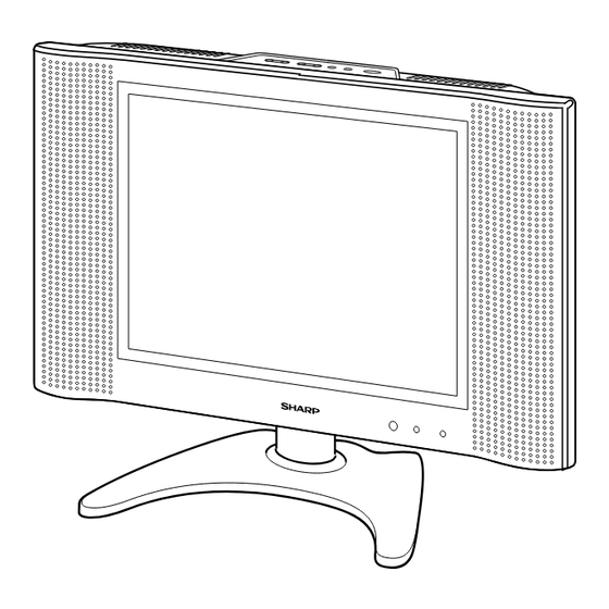
SERVICE MANUAL
LCD COLOUR TELEVISION
MODEL
CONTENTS
SHARP CORPORATION
LC-20B4M
LC-20B4M
S43A4LC-20B4M
Page
Advertisement
Table of Contents

Related Manuals for Sharp LC-20B4M


Summary of Contents for Sharp LC-20B4M
-
Page 1: Table Of Contents
LC-20B4M SERVICE MANUAL S43A4LC-20B4M LCD COLOUR TELEVISION LC-20B4M MODEL In the interests of user-safety (Required by safety regulations in some countries) the set should be re- stored to its original condition and only parts identical to those specified should be used. -
Page 2: Important Service Safety Precaution
LC-20B4M IMPORTANT SERVICE SAFETY PRECAUTION Ë Service work should be performed only by qualified service technicians who are thoroughly familiar with all safety checks and the servicing guidelines which follow: • Use an AC voltmeter having with 5000 ohm per volt, or... - Page 3 LC-20B4M Precautions for using lead-free solder 1 Employing lead-free solder "All PWBs" of this model employs lead-free solder. The LF symbol indicates lead-free solder, and is attached on the PWBs and service manuals. The alphabetical character following LF shows the type of lead-free solder.
-
Page 4: Specifications
Wireless Remote Control, Batteries, Cable clamps, AC adapter, AC cord, Operation manual, Antenna cable As a part of policy of continuous improvement, SHARP reserves the right to make design and specification changes for product improvement without prior notice. The performance specification figures indicated are nominal... -
Page 5: Operation Manual
LC-20B4M OPERATION MANUAL... - Page 6 LC-20B4M...
-
Page 7: Dimensions
LC-20B4M DIMENSIONS Unit: mm MENU V/VIDEO MAIN POWER PRESET 403.3 POWER SLEEP 110.7 76.1 VIDEO AV-IN1 AUDIO VIDEO S-VIDEO AV-IN 2/OUT AUDIO HEAD PHONE COMPONENT ANT. USE THE SUPPLIED AC ADAPTER. (PART NO. LOCATED ON THE MODEL LABEL.) AUDIO POWER INPUT DC13V 249.6... -
Page 8: Removing Of Major Parts
LC-20B4M REMOVING OF MAJOR PARTS 1. Remove the stand fixing screws (4 pcs.). 2. Remove the two terminal covers. 3. Remove the terminal section fixing screws (2 pcs.). 4. Remove the cabinet B fixing screws (12 pcs.). 5. Remove the cabinet B after opening from the direction of an arrow. - Page 9 LC-20B4M 9. Remove the inverter-A PWB fixing screws (2 pcs.). 10. Remove the inverter-B PWB fixing screw (1 pc.). 11. Remove the main PWB fixing screws (3 pcs.). 12. Remove the tuner PWB fixing screws (3 pcs.) and detach the chassis frame cover fixing hooks.
- Page 10 LC-20B4M » Precautions in handling the LCD panels 1. Work in a clean room (with humidities below 50%). 2. Be sure to wear an anti-static armband. 3. Handle the panels on an electro-conductive mat. 4. Be careful not to fall, shake and shock the panels.
- Page 11 LC-20B4M Precautions at the time of the side B(back) service of digital unit. 1. Remove only SC2002 of the FFC for connection between Main unit (SC2002) and Tuner unit(SC3403), and con- nect the extended cable (QCNW-A556WJZZ) for service. 2. Remove the FFC for connection between Main unit (SC1204) and LCD panel unit, and connect the extended cable (QCNW-A553WJZZ) for service.
-
Page 12: Adjusting Procedure Of Each Section
LC-20B4M ADJUSTING PROCEDURE OF EACH SECTION The best adjustment is made before shipping. If any position deviation is found or after part replace is performed, adjust as follows. Preparation for Adjustments Use the exclusive-use AC adapter or stable DC power supply. - Page 13 LC-20B4M 5. Adjustment 5-1. +B adjustment (R3714 Variable resistor) 1) Receive the colour bar signal. 2) Adjust the voltage at pin (4) of P3701 to 5.00 ± 0.02 V. Note: The 5.0 V level is used as reference for all the line voltages. Make this adjustment as precisely as possible.
- Page 14 LC-20B4M 5-5. Other adjustments (SOUND, VPC, DPS, DAC, TUNER, OTHERS, TEXT) 1) Move the cursor to a desired item on page 4 of adjustment process menu. Press the CURSOR LEFT/ RIGHT keys, "VOL (+)/(–)" keys or OK key to select the item.
- Page 15 LC-20B4M 6. Lamp error detection 6-1. Functional description This LCD colour television has a function (lamp error detection) to be turned OFF automatically for safety when the lamp or lamp circuit is abnormal. If the lamp or lamp circuit is abnormal, or some other errors happen, and the lamp error detection is executed, the followings occur.
- Page 16 LC-20B4M 7. Public mode • How to enter into PUBLIC MODE 1. Turn off TV by pressing MAIN POWER switch. 2. While pressing "VOL(+)" key and "CH(ù)" key at the same time, press MAIN POWER switch for more than 2 seconds.
- Page 17 LC-20B4M 8. SOUND ONLY MODE (NO↔YES) (* This item cannot be selected if "NO" appears on the on-screen display.) Let's suppose that this item has been selected and the BRIGHT key on the remote control has been pressed. The item "BRIGHTNESS [OFF]" can now be selected next to the item "BRIGHTNESS [DARK]".
-
Page 18: Trouble Shooting Table
LC-20B4M TROUBLE SHOOTING TABLE No or Wrong Picture Does the IC801 test pattern appear properly? Does the IC1201 test pattern appear properly? Check the IC801 signal Are the waveforms at output line, IC801 itself pins (8), (9), (26), and and its peripheral (27) of IC1201 circuits. - Page 19 LC-20B4M TROUBLE SHOOTING TABLE (Continued)
- Page 20 LC-20B4M TROUBLE SHOOTING TABLE (Continued)
- Page 21 LC-20B4M TROUBLE SHOOTING TABLE (Continued)
-
Page 22: Chassis Layout
LC-20B4M CHASSIS LAYOUT OPERATION Unit MAIN Unit TUNER Unit R/C, LED Unit... - Page 23 LC-20B4M INVERTER-A Unit INVERTER-B Unit...
-
Page 24: Block Diagram
LC-20B4M BLOCK DIAGRAM AGC,AFT,SAW_ SW,MODE 1 ,MODE 2 SC3403 TV_ V TUNER SIF AMP TU3201 Q3201 ,Q3202 V1 _ V AV1 _ L,R INPUT VIDEO S-VIDEO SWITCH V_IN INPUT IC3401 IC3502 V2_V IN/OUT SSTBY INPUT/OUTPUT AV2_L,R IN/OUT AUDIO IN/OUT VIDEO IN/OUT... - Page 25 LC-20B4M SC2002 VIDEO R0~7,G0~7,B0~7 PANEL DECODER CONTROLLER (VPC ) (DPS) FILTER V0,V7,V21 IC801 IC1201 FL801 V64,V112 RE V V176 ,V235 FILTER GRADATION FL802 V2V0 V255 POWER SYNC SEP IC1101 VCOM IC802 CSCO M CSYNC OSD R/G/B VLS,VGL,VEE GSP1,VSH GBLR,GCK POWER...
-
Page 26: Overall Wiring Diagram
LC-20B4M OVERALL WIRING DIAGRAM... - Page 27 LC-20B4M...
-
Page 28: Description Of Schematic Diagram
LC-20B4M DESCRIPTION OF SCHEMATIC DIAGRAM VOLTAGE MEASUREMENT CONDITION: 1. The voltages at test points are measured on exclusive AC adaptor and the stable supply voltage of AC 120V. Signals are fed by a color bar signal generator for servicing purpose and the above voltages are measured with a 20k ohm/V tester. -
Page 29: Schematic Diagram
LC-20B4M SCHEMATIC DIAGRAM Ë R/C, LED and OPERATION Unit... - Page 30 LC-20B4M Ë MAIN Unit-1/7...
- Page 31 LC-20B4M...
- Page 32 LC-20B4M Ë MAIN Unit-2/7...
- Page 33 LC-20B4M...
- Page 34 LC-20B4M Ë MAIN Unit-3/7...
- Page 35 LC-20B4M...
- Page 36 LC-20B4M Ë MAIN Unit-4/7...
- Page 37 LC-20B4M...
- Page 38 LC-20B4M Ë MAIN Unit-5/7...
- Page 39 LC-20B4M...
- Page 40 LC-20B4M Ë MAIN Unit-6/7...
- Page 41 LC-20B4M...
- Page 42 LC-20B4M Ë MAIN Unit-7/7...
- Page 43 LC-20B4M...
- Page 44 LC-20B4M Ë TUNER Unit-1/4 (LC-20B4M)
- Page 45 LC-20B4M...
- Page 46 LC-20B4M Ë TUNER Unit-1/4 (LC-20B4M(X))
- Page 47 LC-20B4M...
- Page 48 LC-20B4M Ë TUNER Unit-2/4...
- Page 49 LC-20B4M...
- Page 50 LC-20B4M Ë TUNER Unit-3/4...
- Page 51 LC-20B4M...
- Page 52 LC-20B4M Ë TUNER Unit-4/4...
- Page 53 LC-20B4M...
- Page 54 LC-20B4M Ë INVERTER-A Unit...
- Page 55 LC-20B4M Ë INVERTER-B Unit...
-
Page 56: Printed Wiring Board Assemblies
LC-20B4M PRINTED WIRING BOARD ASSEMBLIES MAIN Unit (Side-A) - Page 57 LC-20B4M TP2041 SC1204 C1227 C1228 C1229 C1230 C1231 C1232 C1233 R837 R841 R836 C851 C852 R1233 R1231 R1258 C853 IC801 R847 R832 R833 R844 R1224 C875 R845 C835 R875 L808 L806 R827 C1204 C1205 C1206 C1207 C1208 C872 R1217 R1216...
- Page 58 LC-20B4M MAIN Unit (Side-B)
- Page 59 LC-20B4M R1245 C1239 R1243 C1241 R1248 C830 R7006 R830 C810 R815 C821 C815 R817 Q804 C823 R824 R1249 D1201 C828 D1202 IC808 D1204 R829 D1203 R871 C832 R1250 C801 R1255 C802 D1206 Q1210 C1238 C805 D1205 IC1202 R859 R865 IC803...
- Page 60 LC-20B4M R/C, LED Unit (Side-A) D4022 R4023 Q4001 D4012 Q4007 SLD4001 R4024 RMC4002 D4014 D4011 R4029 R/C, LED Unit (Chip Parts Side-A) OPERATION Unit (Side-A) (QPWBSB770WJN2) S4701 OPERATION Unit (Chip Parts Side-A) (QPWBSB770WJN2)
- Page 61 LC-20B4M TUNER Unit (Side-A)
- Page 62 LC-20B4M TP3701 P3604 P3603 P3502 Q3601 FH3704 FH3703 FH3702 FH3701 R3754 Q3709 C3732 R3749 R3745 R374 R3746 C3731 C3730 R3747 C3734 R3744 Q3707 R3737 R372 R3734 C3729 Q3708 TU3201 C372 R3732 L3701 FB37 D370 R3204 C3722 C3024 R3206 C3360 C3202...
- Page 63 LC-20B4M P3301 P3602 P3302 P3601 R3351 R3601 R3352 R3350 R3603 D3604 R3602 P3701 C3610 C3608 R3605 R3606 D3606 Q3604 Q3605 R3515 R3610 R3754 D3607 R3761 Q3709 C3607 R3609 C3732 D3608 R3749 R3745 R3742 R3746 C3731 R3743 R3349 R3347 C3730 R3747...
- Page 64 LC-20B4M INVERTER-A Unit (Side-A)
- Page 65 LC-20B4M R6722 Q6706 C6712 C6713 T6705 R6710 Q6707 R6727 C6727 D6700 R6705 R6726 R6725 Q6704 R6721 Q6703 R6707 C6708 T6704 R6706 R6704 FH6701 FH6700 T6703 T6702 Q6701 C6702 R6720 Q6702 Q6700 T6701 T6700 INVERTER-A Unit (Chip Parts Side-A)
- Page 66 LC-20B4M INVERTER-B Unit (Side-A)
- Page 67 LC-20B4M T6709 T6708 R6716 T6707 Q6714 R6724 C6740 T6706 D6701 R6715 C6718 R6714 FH6707 FH6706 INVERTER-B Unit (Chip Parts Side-A)
-
Page 68: Replacement Parts List
LC-20B4M Ref. No. Part No. Description Code Ref. No. Part No. Description Code PARTS LIST DUNTKB750FE06 PARTS REPLACEMENT MAIN UNIT INTEGRATED CIRCUITS Replacement parts which have these special safety characteristics IC701 VSUMX2N++++-1Y J UMX2N identified in this manual; electrical components having such features... - Page 69 LC-20B4M Ref. No. Part No. Description Code Ref. No. Part No. Description Code DUNTKB750FE06 C814 VCKYCY1AB105KY J 1 Ceramic C815 VCKYCY1HB102KY J 1000p 50V Ceramic MAIN UNIT (Continued) C818 RC-EZA135WJZZY J 4.7 6.3V Electrolytic C819 VCKYCY1EF104ZY J 0.1 Ceramic D707...
- Page 70 LC-20B4M Ref. No. Part No. Description Code Ref. No. Part No. Description Code DUNTKB750FE06 C1650 VCKYCY1EF104ZY J 0.1 Ceramic C1651 VCCCCY1HH471JY J 470p Ceramic MAIN UNIT (Continued) C1652 VCCCCY1HH471JY J 470p Ceramic C2002 VCKYTV1CF105ZY J 1 Ceramic C2003 RC-KZ0074TAZZY J 10 6.3V Ceramic...
- Page 71 LC-20B4M Ref. No. Part No. Description Code Ref. No. Part No. Description Code DUNTKB750FE06 R1611 VRS-CY1JF132JY J 1.3k 1/16W Metal Oxide R1612 VRS-CY1JF000JY 1/16W Metal Oxide MAIN UNIT (Continued) R1614 VRS-CY1JF223JY J 22k 1/16W Metal Oxide R1615 VRS-CY1JF223JY J 22k...
- Page 72 R2066 VRS-CA1JF101JY J 100 1/16W Metal Oxide ASSEMBLY BUT NOT INDEPENDENTLY. R2067 VRS-CY1JF223JY J 22k 1/16W Metal Oxide TU3201 VTUVT2U5CD553 J Tuner (LC-20B4M) R2068 VRS-CY1JF101JY J 100 1/16W Metal Oxide TU3201 VTUVT2U5CD558 J Tuner (LC-20B4M(X)) R2069 VRS-CY1JF000JY 1/16W Metal Oxide...
- Page 73 LC-20B4M Ref. No. Part No. Description Code Ref. No. Part No. Description Code DUNTKB768FE09 (LC-20B4M) C3338 RC-KZA041WJZZY J 10 Ceramic DUNTKB768FE12 (LC-20B4M(X)) C3339 RC-EZA130WJZZY J 3.3 Electrolytic C3340 VCKYCY1EF104ZY J 0.1 Ceramic TUNER UNIT (Continued) C3341 VCCCCY1HH101JY J 100p Ceramic...
- Page 74 LC-20B4M Ref. No. Part No. Description Code Ref. No. Part No. Description Code DUNTKB768FE09 (LC-20B4M) R3339 VRS-CY1JF103JY J 10k 1/16W Metal Oxide DUNTKB768FE12 (LC-20B4M(X)) R3340 VRS-CY1JF103JY J 10k 1/16W Metal Oxide R3341 VRS-CY1JF561JY J 560 1/16W Metal Oxide TUNER UNIT (Continued)
- Page 75 LC-20B4M Ref. No. Part No. Description Code Ref. No. Part No. Description Code DUNTKB768FE09 (LC-20B4M) FH3703 QFSHD1002CEZZ J Fuse Holder DUNTKB768FE12 (LC-20B4M(X)) FH3704 QFSHD1002CEZZ J Fuse Holder FB3701 RBLN-0095CEZZY J Ferrite Bead TUNER UNIT (Continued) FB3702 RBLN-0095CEZZY J Ferrite Bead...
-
Page 76: Operation Unit
LC-20B4M Ref. No. Part No. Description Code Ref. No. Part No. Description Code DUNTKB769FE09 (LC-20B4M) DUNTKB770FE09 (LC-20B4M) DUNTKB769FE12 (LC-20B4M(X)) DUNTKB770FE12 (LC-20B4M(X)) R/C, LED UNIT OPERATION UNIT TRANSISTORS DIODES Q4001 VSDTC144EE/-1Y J DTC144EE D4008 RH-EX1283CEZZY J Zener Diode, 12V Q4003 VSDTC144EE/-1Y... - Page 77 LC-20B4M Ref. No. Part No. Description Code Ref. No. Part No. Description Code DUNTKB590DE02 DUNTKB591DE02 INVERTER-A UNIT INVERTER-B UNIT TRANSISTORS TRANSISTORS Q6700 VS2SC5886++-1Y J 2SC5886 Q6709 VS2SC5886++-1Y J 2SC5886 Q6701 VS2SC5886++-1Y J 2SC5886 Q6710 VS2SC5886++-1Y J 2SC5886 Q6702 VS2SA1530AR-1Y J 2SA1530AR...
- Page 78 J Connecting Cord(MB) 1-14 XEBSD40P10000 J Screw, x8 QCNW-B310WJZZ J Connecting Cord(MR) LX-BZ3442CEFF J Screw, x4 CCABBA220WJ04 J Cabinet B Ass’y(LC-20B4M) BB XBBSD40P06000 J Screw, x4 CCABBA220WJ05 J Cabinet B Ass’y XBBSF30P06000 J Screw, x2 (LC-20B4M(X)) XBPSD30P10JS0 J Screw, x8 Not Available –...
- Page 79 LC-20B4M CABINET AND MECHANICAL PARTS OPERATION PWB INVERTER-A PWB 1-10 1-14 MAIN PWB 1-11 1-13 INVERTER-B 1-10 1-14 1-13 1-12 R/C, LED PWB TUNER PWB 5-2-1 5-18 5-2-3 5-19 5-10 5-2-2 5-14 5-15 5-16 5-20 5-13 5-12 5-18 5-17 5-11...
-
Page 80: Packing Parts
PACKING PARTS ACCESSORIES (NOT REPLACEMENT ITEM) LHLDWA002WJSA J Cable Clamp, x2 SPAKCA711WJZZ – Packing Case — å QACCKA006WJPZ J AC Cord(LC-20B4M) SPAKFA258WJZZ – Buffer Material(Accessories) — å QACCL0026TAZZ J AC Cord(LC-20B4M(X)) SPAKPA209WJZZ – Wrapping Paper — QCNWG0008CEPZ J Antenna Cable SPAKXA220WJZZ –... -
Page 81: Packing Of The Set
LC-20B4M PACKING OF THE SET Operation Manual Polyethylene Bag (TiNS-A742WJZZ) (SSAKA0160CEZZ) Cable Clamp (2 pcs.) (LHLDWA002WJSA) "AAA" size Battery (2 pcs.) AC Cord (QACCKA006WJPZ:LC-20B4M) (QACCL0026TAZZ:LC-20B4M AC Adapter (UADP-0241CEPZ) Wrapping Paper Antenna Cable (SPAKPA209WJZZ) (QCNWG0008CEPZ) Infrared R/C Unit (RRMCGA160WJSA) Buffer Material (Accessories) - Page 82 LC-20B4M COPYRIGHT © 2003 BY SHARP CORPORATION ALL RIGHTS RESERVED. No part of this publication may be reproduced, stored in a retrieval system, or transmitted in any form or by any means, electronic, mechanical, photocopying, recording, or otherwise, without prior written permission of the publisher.