Table of Contents
Advertisement
Advertisement
Table of Contents

Related Manuals for Panasonic MDF-U700VX-PB


Summary of Contents for Panasonic MDF-U700VX-PB
-
Page 1: Operating Instructions
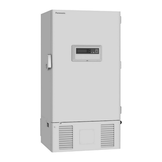
Operating Instructions Ultra-Low Temperature Freezer MDF-U700VX MDF-U700VXC MDF-U700VX MDF-U700VXC Series Please read these instructions carefully before using this product, and save this operating instructions for future use. See page 54 for all Model Numbers. -
Page 2: Table Of Contents
CONTENTS INTRODUCTION P. 2 PRECAUTIONS FOR SAFE OPERATION P. 3 ENVIRONMENTAL CONDITIONS P. 7 FREEZER COMPONENTS P. 8 Control panel P. 10 REMOTE ALARM TERMINAL P. 11 AIR INTAKE PORT P. 11 INSTALLATION SITE P. 12 INSTALLATION P. 13 START-UP OF UNIT P. -
Page 3: Introduction
INTRODUCTION Read this operating instructions carefully before using the appliance and follow the instructions for safety operation. Our company never guarantee any safety if the appliance is used for any objects other than intended use or used by any procedures other than those mentioned in this operating instructions. Keep this operating instructions in an adequate place to refer to it as necessary. -
Page 4: Precautions For Safe Operation
PRECAUTIONS FOR SAFE OPERATION It is imperative that the user complies with this operating instructions as it contains important safety advice. Items and procedures are described so that you can use this unit correctly and safely. If the precautions advised are followed, this will prevent possible injury to the user and any other person. - Page 5 PRECAUTIONS FOR SAFE OPERATION WARNING Do not use the unit outdoors. Current leakage or electric shock may result if the unit is exposed to rain water. Only qualified engineers or service personnel should install the unit. The installation by unqualified personnel may cause electric shock or fire. Install the unit on a sturdy floor and take an adequate precaution to prevent the unit from turning over.
- Page 6 PRECAUTIONS FOR SAFE OPERATION WARNING Ensure you do not inhale or consume medication or aerosols from around the unit at the time of maintenance. These may be harmful to your health. Never splash water directly onto the unit as this may cause electric shock or short circuit. Never put cylinders with liquid on the unit as this may cause electric shock or short circuit when the liquid is spilled.
- Page 7 PRECAUTIONS FOR SAFE OPERATION CAUTION This unit must be plug into a dedicated circuit protected by branch circuit breaker. Use a dedicated power source as indicated on the rating label attached to the unit. A multiple-tap may cause fire resulting from abnormal heating. Connect the power supply plug to the power source firmly after removing the dust on the plug.
-
Page 8: Environmental Conditions
ENVIRONMENTAL CONDITIONS This equipment is designed to be safe at least under the following conditions (based on the IEC 61010-1): Indoor use; Altitude up to 2000 m; Ambient temperature 5 C to 40 Maximum relative humidity 80% for temperature up to 31 C decreasing linearly to 50% relative humidity at 40 Mains supply voltage fluctuations up to ±10% of the nominal voltage;... -
Page 9: Freezer Components
FREEZER COMPONENTS POWER A compressor B compressor Rear side... - Page 10 FREEZER COMPONENTS 1. Outer door: To open the door, grip the handle. On closing, lock the door latch completely. 2. Inner door: The operation of the inner door should be quick to minimize the temperature rise in chamber. Lock the inner door latch completely when the inner door is closed. The inner door is removable for cleaning or defrosting.
-
Page 11: Control Panel
FREEZER COMPONENTS Control panel 1. LCD panel 2. Alarm lamp (ALARM): This lamp is flashed during alarm condition. 3. Figure input key: User for operation setting. 4. Menu button (MENU): To open the menu window during setting. 5. Shift key (Upward, downward, rightward, leftward): To move the cursor on the LCD panel during setting. -
Page 12: Remote Alarm Terminal
REMOTE ALARM TERMINAL The terminal of the remote alarm is installed at the lower left side of the unit. The alarm is outputted from this terminal. Contact capacity is DC 30 V, 2 A. Contact output: between COM. and N.O. between COM. -
Page 13: Installation Site
INSTALLATION SITE To operate this unit properly and to obtain maximum performance, install the unit in a location with the following conditions: A location not subjected to direct sunlight Do not install the unit under direct sunlight. Installation in a location subjected to direct sunlight cannot obtain the intended performance. -
Page 14: Installation
INSTALLATION 1. Remove the packaging materials and tapes Remove all transportation packaging materials and tapes. Open the doors and ventilate the unit. If the outside panels are dirty, clean them with a diluted neutral dishwashing detergent. (Undiluted detergent can damage the plastic components. For the dilution, refer to the instruction of the detergent.) After the cleaning with the diluted detergent, always wipe it off with a wet cloth. -
Page 15: Start-Up Of Unit
START-UP OF UNIT Follow the procedures for the initial and consequent operations of the unit. 1. Connect the power cord to the dedicated outlet having appropriate rating with the chamber empty, and turn on the power switch on the freezer. 2. -
Page 16: Function Of Control Panel
FUNCTION OF CONTROL PANEL The following functions are available through control panel:. 1. Setting of standby operation: To set a running condition at the start-up.(refer to page 17) 2. Setting of log interval and sending to PC: To set a log interval (page 30) and to send a log date to PC. -
Page 17: Top Screen Of Control Panel
TOP SCREEN OF CONTROL PANEL When the power switch is turned on, the top screen is displayed on the LCD panel. 1. Operation indication (Control): "Normal" (initialization value) is indicated by the normal operation. "ECO" is indicated in the saving energy mode. Refer to page 27. 2. -
Page 18: Running Operation (Menu/Set)
RUNNING OPERATION (MENU/Set) This product is operated with set temperature at the time of start-up. 1. With the top screen displayed, press the menu button (MENU) to show the menu window. Select “Set”, and press the enter key (ENTER). 2. A setup screen (Temp. Setting) is displayed. Set up each parameter. 1. -
Page 19: Chamber Temperature Setting (Temperature)
RUNNING OPERATION (MENU/Set) Chamber temperature setting (Temperature) Table 1 shows the top procedure for setting the chamber temperature. Perform key operations in the sequence indicated in the table. The example in the table is based on the assumption that the desired temperature is -75 Note: The unit is set at the factory that the chamber temperature -80 C. -
Page 20: Alarm Temp. Setting (High Alarm/Low Alarm)
RUNNING OPERATION (MENU/Set) Alarm temp. setting (High Alarm/Low Alarm) As an example, Table 2 shows the procedure to set the high temperature alarm so that the alarm can activate when the chamber temperature is 5 C higher than the set temperature. Table 3 shows the procedure to set the low temperature alarm so that the alarm can activate when the chamber temperature is 5 C lower than the set temperature. -
Page 21: Alarm Delay Time Setting (Alarm Delay)
RUNNING OPERATION (MENU/Set) Alarm delay time setting (Alarm Delay) The setting range for delay time is between 0 and 15 minutes. I When 0 is set, the alarm buzzer sound without delay. The factory setting is 15 minutes. Table 4 shows the top procedure for setting the alarm delay time. -
Page 22: Ring Back Of Alarm Buzzer Setting (Ring Back)
RUNNING OPERATION (MENU/Set) Ring back of alarm buzzer setting (Ring Back) The alarm buzzer is silenced by pressing buzzer stop key (BUZZER) on the control panel during alarm condition (The remote alarm sound and lamp are not silenced.). The buzzer will be activated again after certain suspension if the alarm condition is continued. -
Page 23: Key Lock Function
RUNNING OPERATION (MENU/Set) Key lock function This unit is provided with the key lock function. When the key lock is ON, change of temperature setting through the key pad is not available. The key lock is set in OFF at the factory. If a key lock is on, a temperature selection screen can be seen. -
Page 24: Key Lock Release Function
RUNNING OPERATION (MENU/Set) Key lock release function Table 7. Procedure for key unlock setting (Change from Lock to Unlock) (Factory setting of PW is “0000”.) Description of operation Key operated Indication after operation ----- Top screen is displayed The menu window is indicated. And the MENU Press the MENU button. -
Page 25: Various Setting (Menu/Log)
VARIOUS SETTING (MENU/Log) Display of log (Log) This product has the function to record chamber temperature. (Initialization value is for about 5 weeks by the record interval for fifteen minutes.) This record is seen by the log indication (Log) of the display, or data can be transmitted to the personal computer.A setup example is shown in the following. -
Page 26: Indication Of Log And Transmission
VARIOUS SETTING (MENU/Log) Indication of log and transmission Table 9 : Display indication and the process to transmit past all date chamber temperature record value Key operated Description of operation Indication after operation ----- Top screen is displayed The menu window is indicated. And the Press the MENU button. - Page 27 C : Start from ¥Program Files¥ Windows NT¥hypertrm.exe. 2. Set up the following through the hyper-terminal screen. New connection Name (Example) Panasonic Setup of the connection Connecting port COM1 Properties of COM1 Setup of the port Bit/sec.: 9600 Data bit: 8 Parity: No Stop bit: 1 Flow control: Xon / Xoff...
-
Page 28: Various Setting (Menu/Tools)
VARIOUS SETTING (MENU/Tools) Initialization (Tools/Default Setting) 1. Choose initialization (Default Setting) with a shift key in the top screen (Select Tools). An initialization screen is indicated when a menu button (MENU) is pressed and made to indicate a menu window and OK is chosen and an enter key (ENTER) is pressed. -
Page 29: Set Of Date, Time, Log Interval (Tools/Date Time)
VARIOUS SETTING (MENU/Tools) Set of date, time, log interval (Tools/Date Time) A date, time and a Log interval configuration screen (Date Time) are chosen on the top screen (Select Tools). Then, each parameter is set up on the date, time setup screen (Date Time). Each parameter setting range: 1. -
Page 30: Set Of Door Alarm Delay Time (Tools/Door Delay)
VARIOUS SETTING (MENU/Tools) Set of door alarm delay time (Tools/Door Delay) This product has the setup function of the door alarm delay time. (Factory setting is 2 minutes.) The variable range of the door alarm delay time is 0-minute-15 minutes. (An alarm rings when a door opens if a setup is a 0.) A setup example is the following. -
Page 31: Set Of Log Interval (Tools/Log Interval)
VARIOUS SETTING (MENU/Tools) Set of log interval (Tools/Log Interval) This product can change the set point of the log interval (Log Interval) until 2 minute - 30 minutes. (Factory setting is 15 minutes.) It can be recorded for about 5 weeks if it is a log interval for 15 minutes. Table 12 The log interval set-up steps of the log (When a log interval is changed from 15 minutes to 10 minutes.) Description of operation... -
Page 32: Change Of Compressor Delay Time (Tools/Comp. Delay)
VARIOUS SETTING (MENU/Tools) Change of compressor delay time (Tools/Comp. Delay) There is a starting delay time setup (Comp Delay) of A compressor /B compressor in the power failure recovery in this product. Setting can be set from 3 to15 minutes. A compressor setup in the factory shipment is 3 minutes. -
Page 33: Set Of Key Lock Password (Tools/Key Lock Pw Setting)
VARIOUS SETTING (MENU/Tools) Set of key lock password(Tools/Key Lock PW Setting) 1. On the setting screen (Select Tools), select “Key Lock PW Setting”, select “OK” and press the enter key (ENTER). Input the present password (4 digits), select “OK” and press the enter key (ENTER). (Factory setting is 0000.) K e y L o c k . -
Page 34: Monitor Of Freezer Status
MONITOR OF FREEZER STATUS This product has the operation monitor system which shows it in the table 14. It is the system to inform it of the operation conditions of the product. Operation conditions are indicated in the Status indication of the top screen and the message indication. -
Page 35: Alarms & Safety Functions
ALARMS & SAFETY FUNCTIONS This product has the alarm & safety function of the table 15. Table 15 Alarm & safety function list Safety Alarm & safety Situation Indication Buzzer operation Alarm lamp flashed If the chamber temperature is Temp. indicator is flashed higher than the temperature at High temp. - Page 36 ALARMS & SAFETY FUNCTIONS Table 15. Alarms & safety function list Alarm & safety Situation Indication Buzzer Safety operation Message indication: If the thermal sensor is disconnected. “Error E01: Temp Sensor Remote alarm. Open.” Intermittent tone Unit is continuous Message indication: running.
-
Page 37: Routine Maintenance
ROUTINE MAINTENANCE WARNING Always disconnect the power supply to the unit prior to any repair or maintenance of the unit in order to prevent electric shock or injury. Ensure you do not inhale or consume medication or aerosols from around the unit at the time of maintenance. -
Page 38: Cleaning Of Air Intake Port
ROUTINE MAINTENANCE Cleaning of air intake port The cap of the left side is turned counterclockwise, and this product is removed, and the outer air is adopted into the chamber, and it opens a outer door. Therefore, frost is easy to be settled around the air intake port inside the chamber. -
Page 39: Troubleshooting
TROUBLESHOOTING If the unit malfunctions, check out the following before calling for service. Malfunction Check/Remedy The unit is not connected to the power supply. If nothing operates even There is a power failure. when switched on The fuse is blown or the circuit breaker is activated. Investigate the following cause when an alarm display lamp and An alarm system works buzzer sound are working. -
Page 40: Disposal Of Unit
DISPOSAL OF UNIT WARNING If the unit is to be stored unused in an unsupervised area for an extended period ensure that children do not have access and doors cannot be closed completely with a key. The disposal of the unit should be accomplished by appropriate personnel. Always remove doors to prevent accidents such as suffocation. - Page 41 The symbol mark and recycling systems described below apply to EU countries and do not apply to countries in other areas of the world. Your Panasonic product is designed and manufactured with high quality materials and components which can be recycled and/or reused.
- Page 42 POUR LES UTILISATEURS DE UE Le symbole et les systèmes de recyclage évoqués ci-dessous s'appliquent uniquement aux pays de UE. Votre produit Panasonic est conçu et fabriqué avec des composants et des matériaux de hautes qualités qui peuvent être recyclés et/ou réutilisés.
- Page 43 O símbolo e os sistemas de reciclagem descritos abaixo aplicam-se aos países da UE e não se aplicam aos países noutras áreas do mundo. O seu produto Panasonic foi concebido e fabricado com materiais e componentes de elevada qualidade que podem ser reciclados e/ou reutilizados.
- Page 44 Het symbool en de recycleersystemen die hieronder beschreven worden, zijn van toepassing op de landen in de EU en zijn niet van toepassing op landen in andere delen van de wereld. Uw Panasonic product is ontworpen en gemaakt met materialen en onderdelen van hoge kwaliteit, die gerecycleerd en opnieuw gebruikt kunnen worden.
-
Page 45: Disposal Of Battery
DISPOSAL OF BATTERY Location of a nickel-metal-hydride battery This unit is provided a nickel-metal-hydride battery for the power failure warning device. The battery is located in the electrical box inside the cover on the lower left side. (Fig. 1) The high voltage components are enclosed in the electrical box. The cover should be removed by a qualified engineer or a service personnel only to prevent the electric shock. -
Page 46: Temperature Recorder (Option)
TEMPERATURE RECORDER (OPTION) WARNING Always disconnect the power supply to the unit prior to attachment of a temperature recorder in order to prevent electric shock or injury. A temperature recorder is available for the freezer as an optional component. The type of the temperature recorder is MTR-G85C and MTR-85H. - Page 47 TEMPERATURE RECORDER (OPTION) <Replacement of battery> Note : This temperature recorder is designed for the manganese battery and the alkaline battery. Do not use a rechargeable battery because the initial voltage of such battery is low. The rechargeable battery may cause the malfunction of recorder or shorten the Fig.
-
Page 48: Setting Of Mtr-G85C
TEMPERATURE RECORDER (OPTION) Setting of MTR-G85C Chart guides Ink pen arm Back-up battery Chart hub cover Ink pen lifter Recording paper Ink pen Chart speed selector Key lock Latch Pilot lamp Fast feed button Power switch Zero adjustment screw Loading the ink pen: 1. - Page 49 TEMPERATURE RECORDER (OPTION) Starting recording and setting the time: Turn the power switch ON. The pen will move inward on the circular recording paper and stop temporarily at the 0% position (equivalent to the 40 C line). Then the pen will Ink pen move to the position which indicates the measured Hour...
-
Page 50: Backup Cooling Kit (Option)
BACKUP COOLING KIT (OPTION) Chamber temperature is the time when -70 C can be holding for Liquid CO backup cooling kit . Keep a liquefied CO cylinder at less than 31 • The above data is the experiment value which uses liquid CO 30L. - Page 51 BACKUP COOLING KIT (OPTION) WARNING As with any equipment that uses CO gas, there is a likelihood of oxygen depletion in the vicinity of the equipment. It is important that you assess the work site to endure there is suitable and sufficient ventilation.
-
Page 52: Small Inner Door (Option)
SMALL INNER DOOR (OPTION) There is an small inner door (MDF-7ID) of the shelf width of the chamber in this product by the option. The user divided into every shelf of the chamber is to change a standard small inner door to MDF-7ID. Refer to an attached operating instruction for the installation of MDF-7ID. -
Page 53: Inventry Rack (Option)
INVENTORY RACK (OPTION) The optional inventory racks (IR-220U, IR-224U) are useful to store the precious materials in the chamber effectively. When the racks are used, it is necessary to adjust the height of the shelves. Set the shelf stopper as shown in the figure below. IR-220U IR-224U NOTE:... -
Page 54: Specifications
SPECIFICATIONS Product name Ultra-Low Temperature Freezer Ultra-Low Temperature Freezer MDF-U700VX MDF-U700VXC External dimensions W1010 mm x D870 mm x H2010 mm Internal dimensions W870 mm x D600 mm x H1400 mm Effective capacity 728 L Exterior Painted steel Interior Painted steel Outer door Painted steel Inner door... -
Page 55: Performance
PERFORMANCE Product name Ultra-Low Temperature Freezer MDF-U700VX Model No. MDF-U700VX-PB MDF-U700VX-PK MDF-U700VX-PE Cooling performance C at the center of the chamber (ambient temperature; 30 C, no load)* Temperature control range C to -86 C (ambient temperature; 30 C, no load) -
Page 56: Safety Check Sheet
CAUTION Please fill in this form before servicing. Hand over this form to the service engineer to keep for his and your safety. Safety check sheet 1. Freezer contents : Risk of infection: Risk of toxicity: Risk from radioactive sources: (List all potentially hazardous materials that have been stored in this unit.) Notes : 2. - Page 57 Printed in Japan 1-1-1 Sakata, Oizumi-Machi, Ora-Gun, Gunma 370-0596 Japan 7FB6P151578002 S0412-20612 © Panasonic Healthcare Co., Ltd. 2012...