Table of Contents
Advertisement
LG
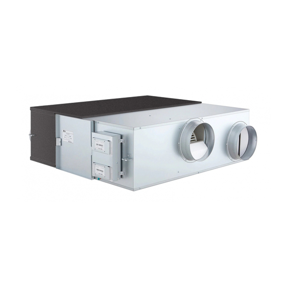
Ventilation System
SERVICE MANUAL
MODELS: LZ-H0106BA0
LZ-H0156BA0
LZ-H0256BA0
LZ-H0506BA0
LZ-H0502BA0
LZ-H0806BA0
LZ-H0802BA0
LZ-H1006BA0
LZ-H1002BA0
LZ-H1506BA0
LZ-H1502BA0
LZ-H2006BA0
LZ-H2002BA0
CAUTION
• BEFORE SERVICING THE UNIT, READ THE SAFETY
PRECAUTIONS IN THIS MANUAL.
• ONLY FOR AUTHORIZED SERVICE PERSONNEL.
website http://www.lgservice.com
LG
Advertisement
Table of Contents

Related Manuals for LG LZ-H0106BA0


Summary of Contents for LG LZ-H0106BA0
- Page 1 Ventilation System SERVICE MANUAL MODELS: LZ-H0106BA0 LZ-H1006BA0 LZ-H0156BA0 LZ-H1002BA0 LZ-H0256BA0 LZ-H1506BA0 LZ-H0506BA0 LZ-H1502BA0 LZ-H0502BA0 LZ-H2006BA0 LZ-H0806BA0 LZ-H0802BA0 LZ-H2002BA0 CAUTION • BEFORE SERVICING THE UNIT, READ THE SAFETY PRECAUTIONS IN THIS MANUAL. • ONLY FOR AUTHORIZED SERVICE PERSONNEL.
-
Page 2: Table Of Contents
Ventilation System Service Manual TABLE OF CONTENTS Safety Precautions....................3 Standards for Model ....................6 Product Standards ....................7 Descriptions for operation and functions ............14 How to disassemble ....................17 Disassemble Diagram(Deal Drawing) and SVC Parts List .......22 Wiring Diagram ....................32 Control Part Detailed Drawing ................36 Descriptions for Control Circuit .................38 Troubleshooting ....................40 Feature Dimensions Diagram ................47... -
Page 3: Safety Precautions
Safety Precautions Safety Precautions To prevent injury to the user or other people and property damage, the following instructions must be followed. I Incorrect operation due to ignoring instruction will cause harm or damage. The seriousness is classified by the following indications. This symbol indicates the possibility of death or serious injury. - Page 4 Safety Precautions Wire with prescribed wire and Install in accordance with Electric works should be undertook fix firmly to prevent it from installation manual. by an expert in accordance with being pulled out by external installation manual and the impact. indicated circuit diagram.
- Page 5 Safety Precautions I For Installation Do not touch electric leakage Install the product in an Do not install in oily place circuit breaker or switch with insulated space. such as kitchen and factory. wet hands. • It may cause electric shock. •...
-
Page 6: Standards For Model
Standards for Model Standards for Model L Z - H 0 5 06B A 0 Serial No. Marking in a developed order. Function A : Basic L : Nano Plasma + Clean(Wall mounted) C : Plasma(Ceiling Cassette) G : Low Static Moter Product Type B: duct type hidden in ceiling T: cassette type for ceiling... -
Page 7: Product Standards
Product Standards Product Standards Item(format) Unit LZ-H0106BA0 Power Ø,V,Hz 1, 220-240, 50 Ventilation Mode Total heat ventilation Wind velocity Super High High Electric current 0.32 0.28 Electricity consumption Airflow External static press Temperature efficiency Heating Enthalpy efficiency Cooling Noise dB(A) - Page 8 Product Standards Item(format) Unit LZ-H0256BA0 Power Ø,V,Hz 1, 220-240, 50 Ventilation Mode Total heat ventilation Wind velocity Super High High Electric current 0.55 0.34 Electricity consumption Airflow External static press Temperature efficiency Heating Enthalpy efficiency Cooling Noise dB(A) Air Filter Non-woven fabric filter Weight Dimensions...
- Page 9 Product Standards Item(format) Unit LZ-H0502BA0 Power Ø,V,Hz 1, 220, 60 Ventilation Mode Total heat ventilation General ventilation Wind velocity Super High High Super High High Electric current 1.25 1.07 1.25 1.07 Electricity consumption Airflow External static press Temperature efficiency Heating Enthalpy efficiency Cooling Noise...
- Page 10 Product Standards Item(format) Unit LZ-H0802BA0 Power Ø,V,Hz 1, 220, 60 Ventilation Mode Total heat ventilation General ventilation Wind velocity Extremely strong Strong Weak(mild) Extremely strong Strong Weak(mild) Electric current Electricity consumption Airflow External static press Temperature efficiency Heating Enthalpy efficiency Cooling Noise dB(A)
- Page 11 Product Standards Item(format) Unit LZ-H1002BA0 Power Ø,V,Hz 1, 220, 60 Ventilation Mode Total heat ventilation General ventilation Wind velocity Extremely strong Strong Weak(mild) Extremely strong Strong Weak(mild) Electric current Electricity consumption Airflow 1,000 1,000 1,000 1,000 External static press Temperature efficiency Heating Enthalpy efficiency Cooling...
- Page 12 Product Standards Item(format) Unit LZ-H1502BA0 Power Ø,V,Hz 1, 220, 60 Ventilation Mode Total heat ventilation General ventilation Wind velocity Super High High Super High High Electric current Electricity consumption 1,190 1,151 1,190 1,151 Airflow 1,500 1,500 1,280 1,500 1,500 1,280 External static press Temperature efficiency Heating...
- Page 13 Product Standards Item(format) Unit LZ-H2002BA0 Power Ø,V,Hz 1, 220, 60 Ventilation Mode Total heat ventilation General ventilation Wind velocity Super High High Super High High Electric current Electricity consumption 1,344 1,306 1,122 1,344 1,306 1,122 Airflow 2,000 2,000 1,600 2,000 2,000 1,600 External static press...
-
Page 14: Descriptions For Operation And Functions
Descriptions for operation and functions Descriptions for operation and functions Main Body Models: LZ-H0106BA0 / LZ-H0156BA0 1. Blower for Air Supply A blower for sucking outside air. 5. Total Heat Exchanger 2. Control Box Exchanges temperature and moisture between air supply air and exhaust air. - Page 15 Descriptions for operation and functions Models: LZ-H0506BA0 / LZ-H0502BA0 1. Maintenance Cover 5. Control box 2. Air Filter 6. Blower for Exhausting Air It prevents dust from clogging in Total Heat Exchanger. It is a fan for inhaling exterior air into an indoor space. 3.
- Page 16 Descriptions for operation and functions Models: LZ-H1506BA0 / LZ-H1502BA0 / LZ-H2006BA0 / LZ-H2002BA0 1. Maintenance Cover 5. Control box 2. Air Filter 6. Blower for Supplying Air It prevents dust from clogging in Total Heat Exchanger. It is a fan for inhaling exterior air into an indoor space. 3.
-
Page 17: How To Disassemble
How to disassemble How to disassemble In case of service, operate through inspecting tool(hole) installed on the surface of ceiling. For main part disassembly, follow the instructions below. Models: LZ-H0106BA0 / LZ-H0156BA0 Control Box screw control box cover • Unscrew the control box cover, and disassemble. - Page 18 How to disassemble In case of service, operate through inspecting tool(hole) installed on the surface of ceiling. For main part disassembly, follow the instructions below. Models: LZ-H0256BA0 Control Box Control box cover Screw • Unscrew the control box cover, and disassemble. Total Heat Exchanger, Filter •...
- Page 19 How to disassemble In case of service, operate through inspecting tool(hole) installed on the surface of ceiling. For main part disassembly, follow the instructions below. Models: LZ-H0506BA0 / LZ-H0502BA0 Control Box Control box cover • Unscrew the control box cover, and disassemble. Screw Total Heat Exchanger, Filter Maintenance Cover...
- Page 20 How to disassemble In case of service, operate through inspecting tool(hole) installed on the surface of ceiling. For main part disassembly, follow the instructions below. Models: LZ-H0806BA0 / LZ-H0802BA0 / LZ-H1006BA0 / LZ-H1002BA0 Control Box Control box cover • Unscrew the control box cover, and disassemble. Screw Total Heat Exchanger, Filter Maintenance Cover...
- Page 21 How to disassemble In case of service, operate through inspecting tool(hole) installed on the surface of ceiling. For main part disassembly, follow the instructions below. Models: LZ-H1506BA0 / LZ-H1502BA0 / LZ-H2006BA0 / LZ-H2002BA0 Control Box Control box cover Screw • Unscrew the control box cover, and disassemble. Total Heat Exchanger, Filter Maintenance Cover •...
-
Page 22: Disassemble Diagram(Deal Drawing) And Svc Parts List
Disassemble Diagram(Deal Drawing) and SVC Parts List Disassemble Diagram(Deal Drawing) and SVC Parts List Models: LZ-H0106BA0 / LZ-H0156BA0 268714 W0CZZ 263230-1 263230-2 152312 340090 359012 546810 22 Ventilation System... - Page 23 Disassemble Diagram(Deal Drawing) and SVC Parts List SVC Parts List Quantity(Volume/Amount) Location Item Part No. Remarks LZ-H0106BA0 LZ-H0156BA0 359012 FAN ASSEMBLY, BLOWER 5834AC1012C 4681A20068J 546810 MOTOR ASSEMBLY,AC,OUTDOOR 4681A20068H 268714 PCB ASSEMBLY,MAIN 6871A10118E W0CZZ CAPACITOR,FILM,BOX 3H00660P 263230-1 THERMISTOR,NTC 6323A30004L Indoor 263230-2 THERMISTOR,NTC...
- Page 24 Disassemble Diagram(Deal Drawing) and SVC Parts List Models: LZ-H0256BA0 268714 W0CZZ 263230-1 263230-2 152312 340090 359012 546810 24 Ventilation System...
- Page 25 Disassemble Diagram(Deal Drawing) and SVC Parts List SVC Parts List Quantity(Volume/Amount) Location Item Part No. Remarks LZ-H0256BA0 359012 FAN ASSEMBLY, BLOWER 5834AC1012C 546810 MOTOR ASSEMBLY,AC,OUTDOOR 4681A20068M 268714 PCB ASSEMBLY,MAIN 6871A10118E W0CZZ CAPACITOR,FILM,BOX 3H00660P 263230-1 THERMISTOR,NTC 6323A30004L Indoor 263230-2 THERMISTOR,NTC 6323A30004M Outdoor 152312 FILTER ASSEMBLY,AIR CLEANER...
- Page 26 Disassemble Diagram(Deal Drawing) and SVC Parts List Models: LZ-H0506BA0 / LZ-H0502BA0 359012 340090 546810-1 152312 W0CZZ 268714 546810-2 263230-2 146812 263230-1 26 Ventilation System...
- Page 27 Disassemble Diagram(Deal Drawing) and SVC Parts List SVC Parts List Quantity(Volume/Amount) Location Item Part No. Remarks LZ-H0506BA0 / LZ-H0502BA0 359012 FAN ASSEMBLY, BLOWER 5901A20029A 546810-1 AC,MOTOR ASSEMBLY 4681A20028M Indoor 546810-2 AC,MOTOR ASSEMBLY 4681A20028N Oudoor 263230-1 THERMISTOR,NTC 6323A30004G Indoor 263230-2 THERMISTOR,NTC 6323A30004H Outdoor 268714...
- Page 28 Disassemble Diagram(Deal Drawing) and SVC Parts List Models: LZ-H0806BA0 / LZ-H0802BA0 / LZ-H1006BA0 / LZ-H1002BA0 340090 152312 W0CZZ 268714 359012 346810-1 346810-2 349011 263230-2 263230-1 28 Ventilation System...
- Page 29 Disassemble Diagram(Deal Drawing) and SVC Parts List SVC Parts List Quantity(Volume/Amount) Location Item Part No. Remarks LZ-H0806BA0 LZ-H0802BA0 LZ-H1006BA0 LZ-H1002BA0 359012 FAN ASSEMBLY, BLOWER 5901A30005A 346810-1 MOTOR ASSEMBLY,AC,INDOOR 4681A20139A Indoor 346810-2 MOTOR ASSEMBLY,AC,INDOOR 4681A20139B Outdoor 346810-1 MOTOR ASSEMBLY,AC,INDOOR 4681A20139C 263230-1 THERMISTOR,NTC 6323A30004J Indoor 263230-2 THERMISTOR,NTC...
- Page 30 Disassemble Diagram(Deal Drawing) and SVC Parts List Models: LZ-H1506BA0 / LZ-H1502BA0 / LZ-H2006BA0 / LZ-H2002BA0 340090 152312 W0CZZ 359012 268711 346810-2 346810-1 567480-2 567480-1 349011 30 Ventilation System...
- Page 31 Disassemble Diagram(Deal Drawing) and SVC Parts List SVC Parts List Quantity(Volume/Amount) Location Item Part No. Remarks LZ-H1506BA0 LZ-H1502BA0 LZ-H2006BA0 LZ-H2002BA0 359012 FAN ASSEMBLY, BLOWER 5901A30005A 346810-1 MOTOR ASSEMBLY,AC,INDOOR 4681A20139A Indoor 346810-2 MOTOR ASSEMBLY,AC,INDOOR 4681A20139B Outdoor 346810-1 MOTOR ASSEMBLY,AC,INDOOR 4681A20139C 263230-1 THERMISTOR,NTC 6323A30004J Indoor 263230-2 THERMISTOR,NTC...
-
Page 32: Wiring Diagram
Wiring Diagram Wiring Diagram Models: LZ-H0106BA0 / LZ-H0156BA0 / LZ-H0256BA0 • This product has different wiring method by system configuration. Perform the wiring work(electric working) on several necessary parts(areas). 32 Ventilation System... - Page 33 Wiring Diagram Models: LZ-H0506BA0 / LZ-H0502BA0 • This product has different wiring method by system configuration. Perform the wiring work(electric working) on several necessary parts(areas). Service Manual 33...
- Page 34 Wiring Diagram Models: LZ-H0806BA0 / LZ-H0802BA0 / LZ-H1006BA0 / LZ-H1002BA0 • This product has different wiring method by system configuration. Perform the wiring work(electric working) on several necessary parts(areas). Capacitor Capacitor Single Phase 220V~50/60Hz Power Supply GN/YL Fan Motor Fan Motor Indoor Unit of Air conditioner Link to Ventilation Damper...
- Page 35 Wiring Diagram Models: LZ-H1506BA0 / LZ-H1502BA0 / LZ-H2006BA0 / LZ-H2002BA0 • This product has different wiring method by system configuration. Perform the wiring work(electric working) on several necessary parts(areas). Capacitor Capacitor Single Phase 220V~50/60Hz Power Supply GN/YL Fan Motor Fan Motor Indoor Unit of Air conditioner Link to Ventilation Damper...
-
Page 36: Control Part Detailed Drawing
Control Part Detailed Drawing Control Part Detailed Drawing Models: LZ-H0106BA0 / LZ-H0156BA0 / LZ-H0256BA0 This product has different wiring method by system configuration. Perform the wiring work(electric working) on several necessary parts(areas). Identification of inside control box FUSE CN-POWER CN-MOTOR-SA... - Page 37 Control Part Detailed Drawing Models: LZ-H0506BA0 / LZ-H0502BA0 / LZ-H0806BA0 / LZ-H0802BA0 / LZ-H1006BA0 / LZ-H1002BA0 / LZ-H1506BA0 / LZ-H1502BA0 / LZ-H2006BA0 / LZ-H2002BA0 This product has different wiring method by system configuration. Perform the wiring work(electric working) on several necessary parts(areas).
-
Page 38: Descriptions For Control Circuit
Descriptions for Control Circuit Descriptions for Control Circuit Models: LZ-H0106BA0 / LZ-H0156BA0 / LZ-H0256BA0 Power Supply Initialization of Micom Controller Input Data Temperature Data (Outdoor Temperature . Room Temperature) Detecting Abnormalities Abnormal condition Normal condition Reliability Operation by Outdoor Temperature... - Page 39 Descriptions for Control Circuit Models: LZ-H0506BA0 / LZ-H0502BA0 / LZ-H0806BA0 / LZ-H0802BA0 / LZ-H1006BA0 / LZ-H1002BA0 / LZ-H1506BA0 / LZ-H1502BA0 / LZ-H2006BA0 / LZ-H2002BA0 Power Supply Initialization of Micom Controller Input Data Temperature Data (Outdoor Temperature . Room Temperature) Detecting Abnormalities Abnormal condition Normal condition Reliability Operation by...
-
Page 40: Troubleshooting
Troubleshooting Troubleshooting Instructions for diagnostics - When separating main PCB, hold the tip of main PCB to prevent any force into over-all parts. - When separating main PCB, be careful of the edge of metal plate. - When pulling or putting a connector on main PCB, do not pull the lead wire, instead pull the entire housing. For the ventilation system failure Failure Possible Causes... - Page 41 Troubleshooting For the remote controller failure Failure Possible Causes Necessary actions No Display on Remote • No power supply to ventilation system • Check power of ventilation system Controller • Longer wiring length of transmission • Check the length of transmission wire wire than standards Impossible to Operate •...
- Page 42 Troubleshooting Instructions for diagnostics - When replacing main PCB, detach the supporter for fixing the main PCB from PCB. - When separating main PCB, be careful of the edge of metal plate. - When pulling or putting a connector on main PCB, do not pull the lead wire, instead pull the entire housing. - After replacing main PCB, establish the switch setting on main PCB in the same manner as the previous main PCB.
- Page 43 Troubleshooting Checking Points Breakdown mode 1 : System does not work normally. After checking the system, check the following checklist. Initial checklist table(table1-1) from installation to operation Checklist Are the switch capacity of main power and wiring diameter in accordance with regulations? Is the prescribed power supplied to power terminal in ventilation system? Is the wiring length of transmission line in accordance with regulations? for wired remote controller : total extension of less than 500m for interlocking air controls : maximum extension...
- Page 44 Troubleshooting System checklist table(table1-2) for using wired remote controller(LCD TYPE) Details Possible Causes Necessary actions • Check the power in ventilation system • No power supplied to ventilation No message displayed system, or incorrect power connected on remote controller to the system •...
- Page 45 Troubleshooting Breakdown mode 3: Remote controller does not work. It works abnormally. Checklist table(table3) for using ZCON-BS2. Details Possible Causes Necessary actions No message displayed • Different transmission line • Check the connection of transmission line on LC screen connection terminal (CN-REMO on the ventilation system panel) •...
- Page 46 Troubleshooting (304) Breakdown mode 4: Ventilation system does not work. It works abnormally. Checklist table(table 4) of ventilation system. Details Possible Causes Necessary actions Fan does not operate. • Connecting failure in control circuit • Check the connection of control circuit failure in fan operation connector or fan related connector connector and lead line connecting connector...
-
Page 47: Feature Dimensions Diagram
Feature Dimensions Diagram Feature Dimensions Diagram LZ-H0106BA0 / LZ-H0156BA0 Control box Suspension Fixture Blower for Supplying Air (Supply Air ) (Exhaust Air) Total Heat Exchanger Air Filter Blower for Exhausting Air (Return Air) (Outdoor Air) Unit: mm Figure Pitch of Suspension Fixture... - Page 48 Feature Dimensions Diagram • LZ-H0256BA0 Total Heat Exchanger Air Filter Maintenance Cover Control box Suspension Fixture er for Supplying Air (Return Air ) (Exhaust Air) Blower for Exhausting Air (Outdoor Air) (Supply Air ) Unit: mm Figure Pitch of Suspension Fixture Duct Connection Flange Duct Pitch Nominal...
- Page 49 Feature Dimensions Diagram • LZ-H0506BA0 / LZ-H0502BA0 Suspension Fixture Blower for Exhausting Air (Return Air) (Exhaust Air) (Outdoor Air) (Supply Air ) Blower for Supplying Air Control box Maintenance Cover Total Heat Exchanger Air Filter Unit: mm Figure Pitch of Suspension Fixture Duct Connection Flange Duct Pitch Nominal...
- Page 50 Feature Dimensions Diagram • LZ-H0806BA0 / LZ-H0802BA0 / LZ-H1006BA0 / LZ-H1002BA0 Suspension Fixture Blower for Exhausting Air (Return Air) (Exhaust Air) (Supply Air) Blower for Supplying Air (Outdoor Air) Control box Maintenance Cover Total Heat Exchange Element Air Filter Unit: mm Figure Pitch of Suspension Fixture Duct Connection Flange...
- Page 51 Feature Dimensions Diagram • LZ-H1506BA0 / LZ-H1502BA0 / LZ-H2006BA0 / LZ-H2002BA0 Suspension Fixture (Return Air) (Exhaust Air) (Supply Air ) (Outdoor Air) Control box Maintenance Cover Total Heat Exchange Element Unit: mm Figure Pitch of Suspension Fixture Duct Connection Flange Nominal Diameter Duct Pitch Weight...
-
Page 52: Accessaries / Option
Accessaries / Option Accessaries / Option Remote Controller (Ventilation System remote controller ZCON-BS2) remote controller is a separate purchase. 1. Display Screen AUTO SWING OPERATION SET TEMP FAN SPEED SUB FUNCTION 2. Heater Button Room Temp AUTO Heater Preheat Defrost Humidify 3. - Page 53 Accessaries / Option HEATER Heater for ventilation system is a separate purchase. Product Standard Model Capacity(W) Connecting Caliber(Ø) PEH-Z4P0 PEH-Z8P0 Unit: mm Figure Pitch of Suspension Fixture Duct Connection Flange Nominal Model Weight Diameter PEH-Z4P0 97.5 PEH-Z8P0 Service Manual 53...
- Page 54 December, 2005 P/No.: 3828A20320D Printed in Korea...