Table of Contents
Advertisement
Quick Links
HP ProLiant DL360 Gen9 Server
User Guide
Abstract
This document is for the person who installs, administers, and troubleshoots servers and storage systems. HP assumes you are qualified in the
servicing of computer equipment and trained in recognizing hazards in products with hazardous energy levels.
Part Number: 767927-001
September 2014
Edition: 1
Advertisement
Table of Contents

Related Manuals for HP ProLiant DL360 Gen9


Summary of Contents for HP ProLiant DL360 Gen9
-
Page 1: User Guide
User Guide Abstract This document is for the person who installs, administers, and troubleshoots servers and storage systems. HP assumes you are qualified in the servicing of computer equipment and trained in recognizing hazards in products with hazardous energy levels. - Page 2 © Copyright 2014 Hewlett-Packard Development Company, L.P. The information contained herein is subject to change without notice. The only warranties for HP products and services are set forth in the express warranty statements accompanying such products and services. Nothing herein should be construed as constituting an additional warranty. HP shall not be liable for technical or editorial errors or omissions contained herein.
-
Page 3: Table Of Contents
Contents Component identification ....................... 7 Front panel components ..........................7 Front panel LEDs and buttons ......................... 8 Power fault LEDs ..........................9 Systems Insight Display LEDs ........................10 Systems Insight Display LED combinations ..................... 11 Rear panel components ..........................12 Rear panel LEDs and buttons ........................ - Page 4 Low profile PCIe slot riser cage option ......................56 GPU riser and cable option ......................... 57 HP Smart Array P440ar Controller option ..................... 59 HP Smart Array P840 Controller board option ....................60 Internal SAS cable option ..........................63 Systems Insight Display module ........................65 FlexibleLOM option ............................
- Page 5 Drivers ............................101 Software and firmware ........................102 Version control ..........................102 HP operating systems and virtualization software support for ProLiant servers ........102 HP Technology Service Portfolio ....................... 102 Change control and proactive notification ..................103 Troubleshooting ........................104 Troubleshooting resources .........................
- Page 6 Index ............................126 Contents 6...
-
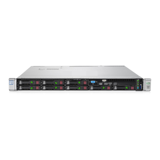
Page 7: Component Identification
Component identification Front panel components • 8 SFF Item Description Serial label pull tab Front video connector (optional) USB 2.0 connector (optional) Optical drive (optional) Systems Insight Display (optional) USB 3.0 connector SAS/SATA/SSD drive bays • 4 LFF Item Description Optical drive (optional) Serial label pull tab Front video connector (optional) -
Page 8: Front Panel Leds And Buttons
Front panel LEDs and buttons • 8 SFF Item Description Status Power On/Standby button Solid green = System on and system power LED* Flashing green (1 Hz/cycle per sec) = Performing power on sequence Solid amber = System in standby Off = No power present** Health LED* Solid green = Normal... -
Page 9: Power Fault Leds
• 4 LFF Item Description Status UID button/LED* Solid blue = Activated Flashing blue: • 1 Hz/cycle per sec = Remote management or firmware upgrade in progress • 4 Hz/cycle per sec = iLO manual reboot sequence initiated • 8 Hz/cycle per sec = iLO manual reboot sequence in progress Off = Deactivated NIC status LED* Solid green = Link to network... -
Page 10: Systems Insight Display Leds
Systems Insight Display LEDs The HP Systems Insight Display LEDs represent the system board layout. The display provides status for all internal LEDs and enables diagnosis with the access panel installed. To view the LEDs, access the HP Systems Insight Display. -
Page 11: Systems Insight Display Led Combinations
Description Status Power supply LEDs Off = Normal Amber = Failed power supply Off = Normal PCI riser LED Amber = Incorrectly installed PCI riser cage Off = Normal Over temp LED Amber = High system temperature detected Off = AMP modes disabled Amp Status LED Solid green = AMP mode enabled Solid amber = Failover... -
Page 12: Rear Panel Components
Health LED Status Systems Insight Display System power LED and color exist: • Redundant power supply is installed and only one power supply is functional. • AC power cord is not plugged into redundant power supply. • Redundant power supply fault •... -
Page 13: Rear Panel Leds And Buttons
UID LED Solid blue = Identification is activated. Flashing blue = System is being managed remotely. Off = Identification is deactivated. HP iLO/standard Solid green = Activity exists. NIC activity LED Flashing green = Activity exists. Off = No activity exists. -
Page 14: Non-Hot-Plug Pci Riser Board Slot Definitions
Item Description Status • Power supply failed • Power supply in standby mode • Power supply exceeded current limit Non-hot-plug PCI riser board slot definitions • Primary riser cage connector, connected to processor 1 or the southbridge PCIe 3-slot riser cage* PCIe 2-slot x16 riser cage PCIe3 x8 (8,4,2,1) PCIe3 x16 (16,8,4,2,1) -
Page 15: System Board Components
SATA port 2 Backplane presence detect connector Optical/SATA port 5 SATA port 4 Front power/USB 3.0 connector HP Smart Storage Battery connector Optional Location Discovery Services connector Drive backplane power connector MicroSD card slot Dual internal USB 3.0 connector... -
Page 16: System Maintenance Switch
IMPORTANT: Before using the S7 switch to change to Legacy BIOS Boot Mode, be sure the HP Dynamic Smart Array B140i Controller is disabled. Do not use the B140i controller when the server is in Legacy BIOS Boot Mode. -
Page 17: Dimm Slots
DIMM slots DIMM slots are numbered sequentially (1 through 12) for each processor. The supported AMP modes use the letter assignments for population guidelines. Device numbers • 4 LFF configuration • 8 SFF configuration Component identification 17... -
Page 18: Hot-Plug Drive Led Definitions
• 10 SFF configuration Hot-plug drive LED definitions Item Status Definition Locate Solid blue The drive is being identified by a host application. Flashing blue The drive carrier firmware is being updated or requires an update. Activity ring Rotating green Drive activity No drive activity Do not remove... - Page 19 • At POST and in the OS, HP iLO performs an orderly shutdown if a cautionary temperature level is detected. If the server hardware detects a critical temperature level before an orderly shutdown occurs, the server performs an immediate shutdown.
-
Page 20: Operations
If an application stops responding, you can use this method to force a shutdown. • Use a virtual power button selection through HP iLO. This method initiates a controlled remote shutdown of applications and the OS before the server enters standby mode. -
Page 21: Remove The Server From The Rack
Connect the peripheral cables and power cords. Remove the server from the rack To remove the server from an HP, Compaq branded, telco, or third-party rack: Power down the server (on page 20). Extend the server from the rack (on page 20). -
Page 22: Remove The Pci Riser Cage
Remove the server from the rack (on page 21). Remove the access panel (on page 21). Remove the fan. CAUTION: Do not operate the server for long periods with the access panel open or removed. Operating the server in this manner results in improper airflow and improper cooling that can lead to thermal damage. -
Page 23: Install The Pci Riser Cage
WARNING: To reduce the risk of personal injury from hot surfaces, allow the drives and the internal system components to cool before touching them. CAUTION: To prevent damage to electrical components, properly ground the server before beginning any installation procedure. Improper grounding can cause ESD. Back up all server data. - Page 24 For instructions on how to extend or remove the server from the rack, see the documentation that ships with the rack rail system. Remove the access panel (on page 21). Install the PCI riser cage. Install the access panel (on page 21). Install the server into the rack.
-
Page 25: Setup
Setup Support and deployment services Delivered by experienced, certified engineers, HP Care Pack services help you keep your servers up and running with support packages tailored specifically for HP ProLiant systems. HP Care Packs let you integrate both hardware and software support into a single package. A number of service level options are available to meet your needs. -
Page 26: Temperature Requirements
HP servers draw in cool air through the front and expel warm air through the rear. Therefore, the front and rear rack doors must be adequately ventilated to allow ambient room air to enter the cabinet, and the rear door must be adequately ventilated to allow the warm air to escape from the cabinet. -
Page 27: Power Requirements
Because of the high ground-leakage currents associated with multiple servers connected to the same power source, HP recommends the use of a PDU that is either permanently wired to the building’s branch circuit or includes a nondetachable cord that is wired to an industrial-style plug. NEMA locking-style plugs or those complying with IEC 60309 are considered suitable for this purpose. -
Page 28: Identifying The Contents Of The Server Shipping Carton
If you are installing the server into a telco rack, order the appropriate option kit at the RackSolutions.com website (http://www.racksolutions.com/hp). Follow the server-specific instructions on the website to install the rack brackets. Use the following information when connecting peripheral cables and power cords to the server. - Page 29 Get help to lift and stabilize the product during installation or removal, especially when the • product is not fastened to the rails. HP recommends that a minimum of two people are required for all rack server installations. A third person may be required to help align the server if the server is installed higher than chest level.
-
Page 30: Powering On And Selecting Boot Options In Uefi Boot Mode
Press the Power On/Standby button. During the initial boot: To modify the server configuration ROM default settings, press the F9 key in the HP ProLiant POST screen to enter the UEFI System Utilities screen. By default, the System Utilities menus are in the English language. -
Page 31: Registering The Server
Remote deployment installation—To deploy an operating system remotely, use Insight Control server deployment for an automated solution. For additional system software and firmware updates, download the HP Service Pack for ProLiant from the HP website (http://www.hp.com/go/spp/download). Software and firmware must be updated before using the server for the first time, unless any installed software or components require an older version. -
Page 32: Hardware Options Installation
Hardware options installation Introduction If more than one option is being installed, read the installation instructions for all the hardware options and identify similar steps to streamline the installation process. WARNING: To reduce the risk of personal injury from hot surfaces, allow the drives and the internal system components to cool before touching them. - Page 33 Open each of the processor locking levers in the order indicated in the following illustration, and then open the processor retaining bracket. Remove the clear processor socket cover. Retain the processor socket cover for future use. CAUTION: THE PINS ON THE SYSTEM BOARD ARE VERY FRAGILE AND EASILY DAMAGED. To avoid damage to the system board, do not touch the processor or the processor socket contacts.
- Page 34 Install the processor. Verify that the processor is fully seated in the processor retaining bracket by visually inspecting the processor installation guides on either side of the processor. THE PINS ON THE SYSTEM BOARD ARE VERY FRAGILE AND EASILY DAMAGED. Close the processor retaining bracket.
- Page 35 Press and hold the processor retaining bracket in place, and then close each processor locking lever. Press only in the area indicated on the processor retaining bracket. CAUTION: Close and hold down the processor cover socket while closing the processor locking levers.
- Page 36 Tighten one pair of diagonally opposite screws halfway, and then tighten the other pair of screws. Finish the installation by completely tightening the screws in the same sequence. Remove the fan blanks from locations 1 and 2. For fan location and numbering information, see "Hot-plug fans (on page 18)"...
-
Page 37: Memory Options
Install the fans into locations 1 and 2. Install the access panel (on page 21). Install the server into the rack. Connect each power cord to the server. Connect each power cord to the power source. Press the Power On/Standby button. The server exits standby mode and applies full power to the system. -
Page 38: Hp Smartmemory
QuickSpecs on the HP website (http://www.hp.com/go/qs). HP SmartMemory HP SmartMemory authenticates and unlocks certain features available only on HP Qualified memory and verifies whether installed memory has passed HP qualification and test processes. Qualified memory is performance-tuned for HP ProLiant and BladeSystem servers and provides future enhanced support through HP Active Health and manageability software. -
Page 39: Single-, Dual-, And Quad-Rank Dimms
Single-, dual-, and quad-rank DIMMs To understand and configure memory protection modes properly, an understanding of single-, dual-, and quad-rank DIMMs is helpful. Some DIMM configuration requirements are based on these classifications. A single-rank DIMM has one set of memory chips that is accessed while writing to or reading from the memory. -
Page 40: Memory Configurations
Advanced Memory Protection options are configured in the BIOS/Platform Configuration (RBSU). If the requested AMP mode is not supported by the installed DIMM configuration, the server boots in Advanced ECC mode. For more information, see the HP UEFI System Utilities User Guide for HP ProLiant Gen9 Servers on the HP website (http://www.hp.com/go/uefi/docs). -
Page 41: Online Spare Memory Configuration
DIMMs should be populated starting farthest from the processor on each channel. • For DIMM spare replacement, install the DIMMs per slot number as instructed by the system software. For more information about server memory, see the HP website (http://www.hp.com/go/memory). DIMM speeds are supported as indicated in the following table. Rank... -
Page 42: Installing A Dimm
• DIMMs may be installed individually. Online spare population guidelines For Online Spare memory mode configurations, observe the following guidelines: • Observe the general DIMM slot population guidelines (on page 41). • Each channel must have a valid online spare configuration. •... -
Page 43: Hot-Plug Hard Drive Guidelines
Install the DIMM. Install the access panel (on page 21). Install the server into the rack. Connect each power cord to the server. Connect each power cord to the power source. Power up the server (on page 20). Use the BIOS/Platform Configuration (RBSU) in the UEFI System Utilities to configure the memory mode. For more information about LEDs and troubleshooting failed DIMMs, see "Systems Insight Display LED combinations (on page 11)."... -
Page 44: Removing The Hard Drive Blank
Removing the hard drive blank Remove the component as indicated. Installing a hot-plug SAS or SATA drive The server can support 8 SAS or SATA hard drives in a SFF configuration, or 10 drives in a SFF configuration with the optional hard drive cage. In a LFF configuration, the server can support 4 SAS or SATA hard drives. To install the component: Remove the drive blank. -
Page 45: Removing A Hot-Plug Sas Or Sata Drive
Install the drive. Removing a hot-plug SAS or SATA drive CAUTION: For proper cooling, do not operate the server without the access panel, baffles, expansion slot covers, or blanks installed. If the server supports hot-plug components, minimize the amount of time the access panel is open. Determine the status of the drive from the hot-plug SAS drive LED combinations ("Hot-plug drive LED definitions"... - Page 46 For instructions on how to extend or remove the server from the rack, see the documentation that ships with the rack rail system. Remove the access panel (on page 21). Remove the universal media bay blank. Install the drive cage assembly, and then tighten the three screws. Hardware options installation 46...
- Page 47 Connect the data cables to the SATA storage connector, the SATA optical/storage drive connector, and the backplane presence detect connector. Connect the power cable to the left power connector on the backplane. CAUTION: To prevent improper cooling and thermal damage, do not operate the server or the enclosure unless all drive and device bays are populated with either a component or a blank.
-
Page 48: Sff Universal Media Bay Option
Install drives or blanks in the empty drive bays. 8 SFF Universal Media Bay option WARNING: To reduce the risk of personal injury from hot surfaces, allow the drives and the internal system components to cool before touching them. CAUTION: To prevent damage to electrical components, properly ground the server before beginning any installation procedure. - Page 49 Remove the universal media bay blank. Install the universal media bay option. 8 SFF DVD-RW/VGA/USB Hardware options installation 49...
- Page 50 8 SFF VGA/USB Route the cables along the edge of the system board, and then connect the cables to the system board. 8 SFF DVD-RW/VGA/USB connections Connect the VGA/USB cable to the Front VGA/USB connector toward the rear of the system board. Connect the SATA optical cable to the SATA optical/storage drive connector.
-
Page 51: Lff Universal Media Bay Option
Connect the VGA/USB cable to the Front VGA/USB connector toward the rear of the system board. Install the access panel (on page 21). Slide the server into the rack. Connect all power cords to the server, and then power up the server. 4 LFF Universal Media Bay option WARNING: To reduce the risk of personal injury from hot surfaces, allow the drives and the... - Page 52 4 LFF optical drive blank 4 LFF VGA/USB blank Install the universal media bay option. 4 LFF optical drive. Hardware options installation 52...
- Page 53 After installing the 4 LFF optical drive, connect the ODD cable to the rear of the drive. 4 LFF VGA/USB Route the cables along the edge of the system board, and then connect the cables to the system board. 4 LFF VGA/USB connections Hardware options installation 53...
-
Page 54: Full Height Pcie X16 Riser Cage Assembly Option
Connect the VGA/USB cable to the Front VGA/USB connector toward the rear of the system board. 4 LFF optical drive connection Connect the SATA optical cable to the SATA optical/storage drive connector. Install the access panel (on page 21). Slide the server into the rack. Connect all power cords to the server, and then power up the server. - Page 55 Back up all server data. Power down the server (on page 20). Do one of the following: Extend the server from the rack (on page 20). Remove the server from the rack (on page 21). For instructions on how to extend or remove the server from the rack, see the documentation that ships with the rack rail system.
-
Page 56: Low Profile Pcie Slot Riser Cage Option
Install the full height PCIe x16 riser cage latch. Align the PCIe x16 riser cage with the corresponding connector on the system board, and then press down on the riser cage. If a GPU is installed in the full height PCIe riser cage option, connect the GPU cable to the riser cage connector and the installed GPU. -
Page 57: Gpu Riser And Cable Option
CAUTION: To prevent damage to electrical components, properly ground the server before beginning any installation procedure. Improper grounding can cause ESD. Back up all server data. Power down the server (on page 20). Do one of the following: Extend the server from the rack (on page 20). Remove the server from the rack (on page 21). - Page 58 Before installing a high-power GPU in the server, be sure that the power supplies support the installation of the option. Because of the high power requirements for the GPU, a 750-W or higher power supply might be required. For more information, see the HP Enterprise Configurator website (http://h30099.www3.hp.com/configurator/).
-
Page 59: Hp Smart Array P440Ar Controller Option
Install the riser cage. Connect the GPU riser cable to the GPU and the primary riser cage PCA. HP Smart Array P440ar Controller option WARNING: To reduce the risk of personal injury from hot surfaces, allow the drives and the internal system components to cool before touching them. -
Page 60: Hp Smart Array P840 Controller Board Option
The P440ar controller with cut heatsink allows for clearance when a GPU is installed in the secondary full height riser cage. HP Smart Array P840 Controller board option WARNING: To reduce the risk of personal injury from hot surfaces, allow the drives and the internal system components to cool before touching them. - Page 61 CAUTION: To prevent damage to electrical components, properly ground the server before beginning any installation procedure. Improper grounding can cause ESD. Back up all server data. Power down the server (on page 20). Do one of the following: Extend the server from the rack (on page 20). Remove the server from the rack (on page 21).
- Page 62 Connect the mini-SAS cables from the standard backplane to port one on the optional P840 controller board. If the optional 2 SFF SAS/SATA backplane is installed, connect the mini-SAS cable from the optional back plane to port two on the P840 controller board. Hardware options installation 62...
-
Page 63: Internal Sas Cable Option
Internal SAS cable option WARNING: To reduce the risk of personal injury from hot surfaces, allow the drives and the internal system components to cool before touching them. CAUTION: To prevent damage to electrical components, properly ground the server before beginning any installation procedure. - Page 64 Install the controller board into slot 2 of the riser cage. Install the riser cage in the server ("Install the PCI riser cage" on page 23). Connect the cables from port one and two on the backplane to port one on the P440 controller board. If the H240 controller board is installed, the SAS cables will use both ports.
-
Page 65: Systems Insight Display Module
4 LFF Systems Insight Display module WARNING: To reduce the risk of personal injury from hot surfaces, allow the drives and the internal system components to cool before touching them. CAUTION: To prevent damage to electrical components, properly ground the server before beginning any installation procedure. - Page 66 Disconnect the Power/UID/USB cable from the front power button/USB 3.0 connector on the system board. Remove the Power/UID/USB assembly. 8 SFF Hardware options installation 66...
- Page 67 4 LFF CAUTION: When routing cables, always be sure that the cables are not in a position where they can be pinched or crimped. To install the SID module: Guide the SID cable through the front of the server. Install the SID module into the front panel and secure the module to the chassis with the screws from the kit.
- Page 68 8 SFF 4 LFF Hardware options installation 68...
-
Page 69: Flexiblelom Option
Connect the SID cables to the front power button/USB 3.0 connector on the system board. FlexibleLOM option WARNING: To reduce the risk of personal injury from hot surfaces, allow the drives and the internal system components to cool before touching them. CAUTION: To prevent damage to electrical components, properly ground the server before beginning any installation procedure. -
Page 70: Serial Cable Option
Remove the FlexibleLOM PCIe blank. Install the component: Firmly seat the FlexibleLOM in the slot. Tighten the thumbscrew. Install the access panel (on page 21). Slide the server into the rack. Connect the LAN segment cables. Connect each power cord to the server. Connect each power cord to the power source. - Page 71 WARNING: To reduce the risk of personal injury from hot surfaces, allow the drives and the internal system components to cool before touching them. CAUTION: To prevent damage to electrical components, properly ground the server before beginning any installation procedure. Improper grounding can cause ESD. Back up all server data.
-
Page 72: Expansion Board Options
Connect the serial cable option. Then, remove the backing from the double-sided tape and press down where indicated. Expansion board options The server supports PCI Express expansion boards. The server ships with PCIe riser boards and expansion slots. PCIe expansion boards are supported with optional riser boards. Removing the expansion slot blanks WARNING: To reduce the risk of personal injury from hot surfaces, allow the drives and the... - Page 73 Primary PCI riser cage Hardware options installation 73...
-
Page 74: Installing An Expansion Board
Secondary PCI riser cage Installing an expansion board WARNING: To reduce the risk of personal injury from hot surfaces, allow the drives and the internal system components to cool before touching them. CAUTION: To prevent damage to electrical components, properly ground the server before beginning any installation procedure. - Page 75 For instructions on how to extend or remove the server from the rack, see the documentation that ships with the rack rail system. Remove the access panel (on page 21). Remove the primary PCI riser cage ("Remove the PCI riser cage"...
-
Page 76: Location Discovery Services Ear Option
Connect each power cord to the server. Connect each power cord to the power source. Power up the server (on page 20). Location discovery services ear option Remove all power: Disconnect each power cord from the power source. Disconnect each power cord from the server. Remove the access panel (on page 21). - Page 77 Remove the hot-plug fan or fan blank from fan bay 1. Hardware options installation 77...
- Page 78 Remove the location discovery cable protection panel from the left side of the server. Hardware options installation 78...
- Page 79 Remove the standard ear. Install the location discovery services ear option and route the location discovery services cable through side channel. Hardware options installation 79...
- Page 80 Install the discovery cable protection panel. Connect the location discovery services cable to the location discovery services connector on the system board. Hardware options installation 80...
-
Page 81: Hp Trusted Platform Module Option
Do not remove an installed TPM. Once installed, the TPM becomes a permanent part of the system board. • When installing or replacing hardware, HP service providers cannot enable the TPM or the encryption technology. For security reasons, only the customer can enable these features. •... -
Page 82: Installing The Trusted Platform Module Board
Recovery Mode after BitLocker detects a possible compromise of system integrity. • HP is not liable for blocked data access caused by improper TPM use. For operating instructions, see the encryption technology feature documentation provided by the operating system. -
Page 83: Retaining The Recovery Key/Password
Install the TPM board. Press down on the connector to seat the board ("System board components" on page 15). Install the TPM security rivet by pressing the rivet firmly into the system board. Install the PCI riser cage (on page 23). Install the access panel (on page 21). -
Page 84: Enabling The Trusted Platform Module
OS application TPM settings. For more information on firmware updates and hardware procedures, see the HP Trusted Platform Module Best Practices White Paper on the HP website (http://www.hp.com/support). -
Page 85: Cabling
For information on cabling peripheral components, refer to the white paper on high-density deployment at the HP website (http://www.hp.com/products/servers/platforms). CAUTION: When routing cables, always be sure that the cables are not in a position where they can be pinched or crimped. -
Page 86: 8-Sff Universal Media Bay Cabling
Connect the power cable to the left power connector on the backplane. NOTE: Cabling from the 2 SFF backplane will vary if a PCIe storage controller is installed. 8-SFF Universal Media Bay cabling Route the cables along the edge of the system board, and then connect the cables to the system board: •... -
Page 87: 4-Lff Universal Media Bay Cabling
Connect the VGA/USB cable to the Front VGA/USB connector toward the rear of the system board. 4-LFF Universal Media Bay cabling Route the cables along the edge of the system board, and then connect the cables to the system board: •... -
Page 88: Smart Array Controller Cabling
Connect the SATA optical cable to the SATA optical/storage drive connector. Smart Array controller cabling Connect the SAS/SATA cables to the backplane and Smart Array controller. Install the SAS/SATA cables according to their labels as Port 1 or Port 2. These labels are on the cables and their connections. •... -
Page 89: Embedded Sata Cabling
• 4 LFF Embedded SATA cabling WARNING: Eliminate the risk of electric shock by removing all AC power from the system before installing or replacing any non-hot-plug hardware option. Disconnect all power cords to completely remove power from the server. Connect the SATA cables from the backplane to the Mini SAS/SATA connectors on the system board according to their labels as Port 1 or Port 2. - Page 90 Connect the SATA cable from port one on the backplane to port one on the system board as indicated on the connectors. Cabling 90...
-
Page 91: Software And Configuration Utilities
Management. All key internal subsystems are monitored by HP iLO. If enabled, SNMP alerts are sent directly by HP iLO regardless of the host operating system or even if no host operating system is installed. Embedded remote support software is available on HP ProLiant Gen8 and later servers with iLO 4, regardless of the operating system software and without installing OS agents on the server. -
Page 92: Active Health System
Remotely mount high-performance Virtual Media devices to the server. • Securely and remotely control the power state of the managed server. • Implement true Agentless Management with SNMP alerts from HP iLO, regardless of the state of the host server. • Download the Active Health System log. -
Page 93: Hp Restful Api Support For Hp Ilo
HP RESTful API support for HP iLO HP iLO 4 firmware version 2.00 and later includes the HP RESTful API. The HP RESTful API is a management interface that server management tools can use to perform configuration, inventory, and monitoring of an HP ProLiant server via iLO. -
Page 94: Hp Insight Remote Support
HP BladeSystem c-Class enclosures, you can register a server or enclosure to communicate directly to HP Insight Online without the need to set up an HP Insight Remote Support centralized Hosting Device in your local environment. HP Insight Online will be your primary interface for remote support information. -
Page 95: Hp Insight Diagnostics
(http://www.hp.com/go/intelligentprovisioning). For Intelligent Provisioning recovery media downloads, see the Resources tab on the HP website (http://www.hp.com/go/ilo). For consolidated drive and firmware update packages, see the HP Smart Update: Server Firmware and Driver Updates page on the HP website (http://www.hp.com/go/SmartUpdate). HP Insight Diagnostics... -
Page 96: Scripting Toolkit For Windows And Linux
SPP is a comprehensive systems software (drivers and firmware) solution delivered as a single package with major server releases. This solution uses HP SUM as the deployment tool and is tested on all supported HP ProLiant servers including HP ProLiant Gen8 and later servers. -
Page 97: Hp Uefi System Utilities
HP UEFI System Utilities The HP UEFI System Utilities is embedded in the system ROM. The UEFI System Utilities enable you to perform a wide range of configuration activities, including: • Configuring system devices and installed options • Enabling and disabling system features •... -
Page 98: Restoring And Customizing Configuration Settings
OS installation if the defaults are restored. To avoid this issue, use the User Defined Defaults feature in UEFI System Utilities to override the factory default settings. For more information, see the HP UEFI System Utilities User Guide for HP ProLiant Gen9 Servers on the HP website (http://www.hp.com/go/ProLiantUEFI/docs). -
Page 99: Embedded Uefi Shell
Embedded UEFI shell The system BIOS in all HP ProLiant Gen9 servers includes an Embedded UEFI Shell in the ROM. The UEFI Shell environment provides an API, a command line prompt, and a set of CLIs that allow scripting, file manipulation, and system information. -
Page 100: Utilities And Features
Gen8 servers, HP SSA replaces ACU with an enhanced GUI and additional configuration features. HP SSA exists in three interface formats: the HP SSA GUI, the HP SSA CLI, and HP SSA Scripting. Although all formats provide support for configuration tasks, some of the advanced tasks are available in only one format. -
Page 101: Redundant Rom Support
Before the OS loads, HP provides support for USB 2.0 devices through legacy USB support, which is enabled by default in the system ROM. USB 3.0 ports are not functional before the OS loads. The native OS provides USB 3.0 support through appropriate xHCI drivers. -
Page 102: Software And Firmware
HP website (http://www.hp.com/go/spp/download). To locate the drivers for a particular server, go to the HP website (http://www.hp.com/go/hpsc) and click on Drivers, Software & Firmware. Then, enter your product name in the Find an HP product field and click Software and firmware Software and firmware should be updated before using the server for the first time, unless any installed software or components require an older version. -
Page 103: Change Control And Proactive Notification
Change control and proactive notification HP offers Change Control and Proactive Notification to notify customers 30 to 60 days in advance of upcoming hardware and software changes on HP commercial products. -
Page 104: Troubleshooting
• Simplified Chinese (http://www.hp.com/support/Gen9_TSG_zh_cn) The HP ProLiant Gen9 Troubleshooting Guide, Volume II: Error Messages provides a list of error messages and information to assist with interpreting and resolving error messages on ProLiant servers and server blades. To view the guide, select a language: •... -
Page 105: Battery Replacement
Battery replacement If the server no longer automatically displays the correct date and time, you may need to replace the battery that provides power to the real-time clock. WARNING: The computer contains an internal lithium manganese dioxide, a vanadium pentoxide, or an alkaline battery pack. A risk of fire and burns exists if the battery pack is not properly handled. - Page 106 For more information about battery replacement or proper disposal, contact an authorized reseller or an authorized service provider. Battery replacement 106...
-
Page 107: Regulatory Information
Hewlett-Packard Company, Address: 3000 Hanover Street, Palo Alto, California 94304, U.S. Local representative information (Russian) • HP Russia • HP Belarus • HP Kazakhstan Local representative information (Kazakh) Manufacturing date The manufacturing date is defined by the serial number (HP serial number format for this product): CCSYWWZZZZ Regulatory information 107... -
Page 108: Turkey Rohs Material Content Declaration
38 for the week of September 9. Turkey RoHS material content declaration Ukraine RoHS material content declaration Warranty information HP ProLiant and X86 Servers and Options (http://www.hp.com/support/ProLiantServers-Warranties) HP Enterprise Servers (http://www.hp.com/support/EnterpriseServers-Warranties) HP Storage Products (http://www.hp.com/support/Storage-Warranties) HP Networking Products (http://www.hp.com/support/Networking-Warranties) Regulatory information 108... -
Page 109: Electrostatic Discharge
Electrostatic discharge Preventing electrostatic discharge To prevent damaging the system, be aware of the precautions you need to follow when setting up the system or handling parts. A discharge of static electricity from a finger or other conductor may damage system boards or other static-sensitive devices. -
Page 110: Specifications
40°C to 45°C (104°F to 113°F) at sea level with an altitude derating of 1.0°C per every 125 m (1.8°F per every 410 ft) above 900 m (2953 ft) to a maximum of 3048 m (10,000 ft). The approved hardware configurations for this system are listed on the HP website (http://www.hp.com/servers/ASHRAE). -
Page 111: Power Supply Specifications
• HP 800W Flex Slot Platinum Hot-plug Power Supply (on page 112) • HP 1400W Flex Slot Platinum Plus Hot-plug Power Supply (on page 112) For detailed power supply specifications, see the QuickSpecs on the HP website (http://www.hp.com/go/proliant/powersupply). HP 500W Flex Slot Platinum Hot-plug Power Supply... -
Page 112: Hp 800W Flex Slot Platinum Hot-Plug Power Supply
800 W at 100 VAC to 120 VAC Maximum peak power input 800 W at 200 VAC to 240 VAC input HP 1400W Flex Slot Platinum Plus Hot-plug Power Supply Specification Value Input requirements 200 to 240 VAC Rated input voltage... -
Page 113: Hot-Plug Power Supply Calculations
Hot-plug power supply calculations For hot-plug power supply specifications and calculators to determine electrical and heat loading for the server, see the HP Power Advisor website (http://www.hp.com/go/hppoweradvisor). Specifications 113... -
Page 114: Support And Other Resources
Active Health System log (HP ProLiant Gen8 or later products) Download and have available an Active Health System log for 7 days before the failure was detected. For more information, see the HP iLO 4 User Guide or HP Intelligent Provisioning User Guide on the HP website (http://www.hp.com/go/ilo/docs). - Page 115 HP specifies in the materials shipped with a replacement CSR part whether a defective part must be returned to HP. In cases where it is required to return the defective part to HP, you must ship the defective part back to HP within a defined period of time, normally five (5) business days. The defective part must be returned with the associated documentation in the provided shipping material.
- Page 116 HP sono realizzati con numerosi componenti che possono essere riparati direttamente dal cliente (CSR, Customer Self Repair). Se in fase di diagnostica HP (o un centro di servizi o di assistenza HP) identifica il guasto come riparabile mediante un ricambio CSR, HP lo spedirà direttamente al cliente per la sostituzione.
- Page 117 Si, durante la fase de diagnóstico, HP (o los proveedores o socios de servicio de HP) identifica que una reparación puede llevarse a cabo mediante el uso de un componente CSR, HP le enviará dicho componente directamente para que realice su sustitución. Los componentes CSR se clasifican en dos categorías:...
- Page 118 HP se hará cargo de todos los gastos de envío y devolución de componentes y escogerá la empresa de transporte que se utilice para dicho servicio. Para obtener más información acerca del programa de Reparaciones del propio cliente de HP, póngase en contacto con su proveedor de servicios local.
- Page 119 Opcional – Peças cujo reparo feito pelo cliente é opcional. Essas peças também são projetadas para o reparo feito pelo cliente. No entanto, se desejar que a HP as substitua, pode haver ou não a cobrança de taxa adicional, dependendo do tipo de serviço de garantia destinado ao produto.
- Page 120 Support and other resources 120...
- Page 121 Support and other resources 121...
-
Page 122: Acronyms And Abbreviations
Acronyms and abbreviations ABEND abnormal end Array Configuration Utility Advanced Memory Protection Automatic Server Recovery Customer Self Repair HP SIM HP Systems Insight Manager HP SUM HP Smart Update Manager International Electrotechnical Commission Integrated Lights-Out Integrated Management Log large form factor LRDIMM... - Page 123 Power-On Self Test RBSU ROM-Based Setup Utility RDIMM registered dual in-line memory module Rapid Deployment Pack serial attached SCSI SATA serial ATA small form factor Standard Parallel Port Mode HP Smart Storage Administrator TMRA recommended ambient operating temperature Acronyms and abbreviations 123...
- Page 124 Trusted Platform Module unit identification Version Control Agent VCRM Version Control Repository Manager Acronyms and abbreviations 124...
-
Page 125: Documentation Feedback
Documentation feedback HP is committed to providing documentation that meets your needs. To help us improve the documentation, send any errors, suggestions, or comments to Documentation Feedback (mailto:docsfeedback@hp.com). Include the document title and part number, version number, or the URL when submitting your feedback. - Page 126 90, 94, 99 health LEDs 8 diagnostics utility 94 help resources 113 DIMM installation guidelines 39 hot-plug power supply calculations 112 DIMMs 39 HP contact information 113 DIMMs, single- and dual-rank 39 HP Insight Diagnostics 94 Index 126...
- Page 127 HP Insight Diagnostics survey functionality 94 operating systems 30, 101 HP Insight Remote Support software 93, 101 optimum environment 25 HP Service Pack for ProLiant 90, 94, 95 options installation 28, 32, 43 HP Smart Update Manager overview 90, 95 HP SmartMemory 38...
- Page 128 32 Server mode 90 server options, installing 28, 32 warnings 27 server specifications 109 website, HP 113 shipping carton contents 28 Smart Update Manager 90, 95 space requirements 25 specifications 109, 112 specifications, power 110, 111...