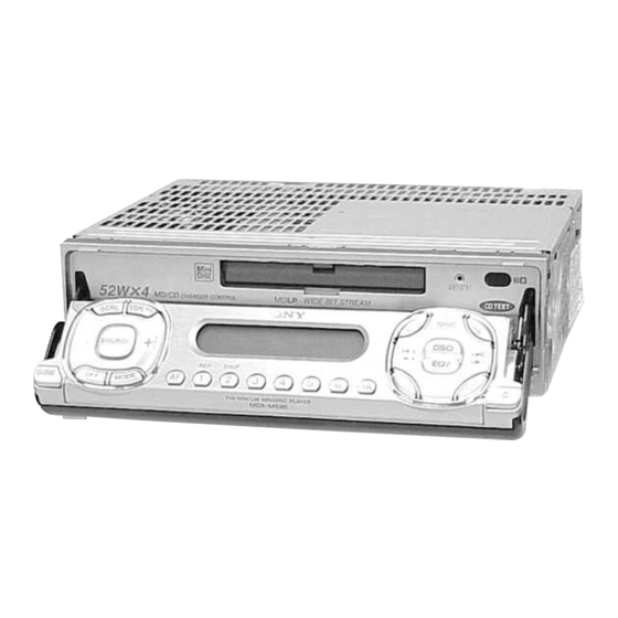
Sony MDX-M690 Service Manual
Fm/mw/lw mini disc player
Hide thumbs
Also See for MDX-M690:
- Operating instructions manual (206 pages) ,
- Operation instructions manual (254 pages) ,
- Installation/connections (2 pages)
Table of Contents
Advertisement
Quick Links
SERVICE MANUAL
Ver 1.0 2001.03
US and foreign patents licensed from Dolby Laboratories.
MD Player section
Signal-to-noise ratio
90 dB
Frequency response
10 – 20,000 Hz
Wow and flutter
Below measurable limit
Tuner section
FM
Tuning range
87.5 – 108.0 MHz
Aerial terminal
External aerial connector
Intermediate frequency
10.7 MHz/450 kHz
Usable sensitivity
8 dBf
Selectivity
75 dB at 400 kHz
Signal-to-noise ratio
66 dB (stereo),
72 dB (mono)
Harmonic distortion at 1 kHz
0.6 % (stereo),
0.3 % (mono)
Separation
35 dB at 1 kHz
Frequency response
30 – 15,000 Hz
MW/LW
Tuning range
MW: 531 – 1,602 kHz
LW: 153 – 279 kHz
Aerial terminal
External aerial connector
Intermediate frequency
10.7 MHz/450 kHz
MW: 30 µV
Sensitivity
LW: 40 µV
Sony Corporation
9-870-294-11
2001C0500-1
Audio Entertainment Group
C 2001.3
General Engineering Dept.
MDX-M690
Model Name Using Similar Mechanism
Base Mechanism Type
Optical Pick-up Name
SPECIFICATIONS
Power amplifier section
Outputs
Speaker outputs
(sure seal connectors)
Speaker impedance
4 – 8 ohms
52 W × 4 (at 4 ohms)
Maximum power output
General
Outputs
Audio outputs (front/rear)
Subwoofer output (mono)
Power aerial relay control
lead
Power amplifier control lead
Inputs
Telephone ATT control lead
Illumination control lead
BUS control input
connector
BUS audio input connector
Remote controller input
connector
Aerial input connector
Bass ±8 dB at 100 Hz
Tone controls
Treble ±8 dB at 10 kHz
FM/MW/LW MINI DISC PLAYER
AEP Model
UK Model
MDX-CA680
MG-164MA-138
KMS-241C
Loudness
+8 dB at 100 Hz
+2 dB at 10 kHz
Power requirements
12 V DC car battery
(negative earth)
Approx. 178 × 50 × 182 mm
Dimensions
(w/h/d)
Approx. 182 × 53 × 160 mm
Mounting dimensions
(w/h/d)
Mass
Approx. 1.5 kg
Supplied accessories
Parts for installation and
connections (1 set)
Front panel case (1)
Card remote commander
RM-X111
Note
This unit cannot be connected to a digital preamplifier
or an equalizer.
Design and specifications are subject to change
without notice.
Advertisement
Table of Contents

Related Manuals for Sony MDX-M690

Summary of Contents for Sony MDX-M690
-
Page 1: Specifications
MDX-M690 SERVICE MANUAL AEP Model UK Model Ver 1.0 2001.03 US and foreign patents licensed from Dolby Laboratories. Model Name Using Similar Mechanism MDX-CA680 Base Mechanism Type MG-164MA-138 Optical Pick-up Name KMS-241C SPECIFICATIONS MD Player section Power amplifier section Loudness... -
Page 2: Table Of Contents
MDX-M690 TABLE OF CONTENTS SERVICING NOTES DIAGRAMS ..........4 6-1. Block Diagram – SERVO Section – ....... 21 GENERAL 6-2. Block Diagram – TUNER Section – ......22 6-3. Block Diagram – MAIN Section – ......... 23 Location of Controls ............5 6-4. - Page 3 LINE WITH MARK 0 ON THE SCHEMATIC DIAGRAMS AND IN THE PARTS LIST ARE CRITICAL TO SAFE OPERATION. REPLACE THESE COMPONENTS WITH SONY PARTS WHOSE PART NUMBERS APPEAR AS SHOWN IN THIS MANUAL OR IN SUPPLEMENTS PUB- LISHED BY SONY.
-
Page 4: Servicing Notes
MDX-M690 SECTION 1 SERVICING NOTES PRECAUTION ON OPEN/CLOSE FRONT PANEL DETACHING THE DISPLAY PANEL IN THE TEST MODE [OPEN] In the normal mode, after pressing the key for two sec- The front panel opens to the bottom of main unit. -
Page 5: General
MDX-M690 SECTION 2 This section is extracted from instruction manual. GENERAL Main display panel Location of controls Card remote commander RM-X111 Refer to the pages listed for details. : During Playback : During radio reception : During menu mode CD/MD... - Page 6 Zorg ervoor dat de kleurcode voor audio overeenkomt met richtigen Buchsen am Gerät zu verbinden. van een auto-antenne de betreffende aansluitingen op het toestel. nur CDX-M670 und MDX-M690 alleen CDX-M670, MDX-M690 Mit dem kabel nach oben einsetzen! Inbrengen met het snoer naar boven...
- Page 7 MDX-M690 Dashboard Fire wall Armaturenbrett Motorraumtrennwand Extended portion of the front panel Tableau de bord Paroi ignifuge Überstehender Teil der Frontplatte Cruscotto Parete tagliafiamma Partie étendue de la façade Dashboard Brandschot Parte sporgente del pannello anteriore Verlengstuk van het frontpaneel...
-
Page 8: Disassembly
MDX-M690 SECTION 3 DISASSEMBLY • This set can be disassembled in the order shown below. 3-1. DISASSEMBLY FLOW Note 1: The process described in can be performed in any order. Note 2: Without completing the process described in , the next process can not be performed. -
Page 9: Cover
MDX-M690 Note: Follow the disassembly procedure in the numerical order given. 3-2. COVER 1 screw (PTT2.6 × 6) 2 cover 3-3. FRONT PANEL (KEY) ASSY 5 Remove the front panel (KEY) assy in the direction of the arrow. 4 screw (panel) -
Page 10: Mechanism Deck (Mg-164Ma-138)
MDX-M690 3-4. MECHANISM DECK (MG-164MA-138) 4 two screws (PTT2.6 × 6) 5 bracket (MD) 1 Remove the solder of sheet (beat). 3 connector (CN401) 6 mechanism deck (MG-164MA-138) 2 screw (PTT2.6 × 4) Note: Make sure to install screw (PTT2.6 × 4). -
Page 11: Sub Panel Assy
MDX-M690 3-6. SUB PANEL ASSY 1 flat cable (CN603) 2 screw (PTT2.6 × 6) 3 claw 3 claw 4 sub panel assy 2 screw (PTT2.6 × 6) 3-7. MAIN BOARD 2 three ground point screws • Cover (flexible), Slider (flexible) and Tension spring (flexible) (PTT2.6 ×... -
Page 12: Heat Sink
MDX-M690 3-8. HEAT SINK 3 cord (with connector) (ANT) 1 two connectors (CN201, 301) 7 screw 2 screw (PTT2.6 × 6) (PTT2.6 × 6) 6 two screws 8 heat sink (PTT2.6 × 10) 4 screw (PTT2.6 × 6) 5 cord (with connector) (sub out) 7 screw (PTT2.6 ×... -
Page 13: Md Cover Assy
MDX-M690 3-10. MD COVER ASSY 1 four screws (BVTT2 × 4) 3 MD cover assy shaft (MD cover guide) cassette holder 2 Pushing the cassette holder in the direction of the arrow A with a screwdriver, etc., disengage the shaft (MD cover guide) from the slot in the MD cover assy. -
Page 14: Lo Motor Assy (Loading) (M903)
MDX-M690 3-12. LO MOTOR ASSY (LOADING) (M903) 4 Remove the bracket (LO) in the direction of the arrow A . 5 LO motor assy (loading) 1 Remove solders of motor (M903). (M903) 2 tension spring (rack) 3 claw bracket (LO) –... -
Page 15: Holder Assy
MDX-M690 3-14. HOLDER ASSY 4 Remove the holder assy in the direction of the arrow. 2 type-E stop ring 1.5 1 spring (chucking) 2 type-E stop ring 1.5 2 type-E stop ring 1.5 3 lever (lock R) 3 lever (lock L) 1 spring (chucking) 2 type-E stop ring 1.5... -
Page 16: Optical Pick-Up (Kms-241C)
MDX-M690 3-16. OPTICAL PICK-UP (KMS-241C) 4 screw (B2 × 3) 6 bearing (SL) 5 feed screw assy 7 optical pick-up (KMS-241C) 1 two screws 3 screw (K2 × 3) (K2 × 3) 2 guide shaft (OPT L) 3-17. SL MOTOR ASSY (SLED) (M902), SP MOTOR ASSY (SPINDLE) (M901) 4 screw (P1.7 ×... -
Page 17: Assembly
MDX-M690 SECTION 4 ASSEMBLY • This set can be assembled in the order shown below. 4-1. ASSEMBLY FLOW 4-2. MOTOR BLOCK ASSY (Page 18) 4-3. CAM (R) ASSY (Page 18) 4-4. ADJUSTING PHASE OF MOTOR BLOCK ASSY, CAM (R) ASSY (Page 19) 4-5. -
Page 18: Motor Block Assy
MDX-M690 Note: Follow the assembly procedure in the numerical order given. 4-2. MOTOR BLOCK ASSY 7 bracket (L) assy 2 stop ring 1.5 1 cam (L) 6 washer (M) 6 washer (M) hole (large) switch 5 gear (A) hole (small) -
Page 19: Adjusting Phase Of Motor Block Assy, Cam (R) Assy
MDX-M690 4-4. ADJUSTING PHASE OF MOTOR BLOCK ASSY, CAM (R) ASSY 1 Supply the power to the motor. – yellow wiring Voltage : 9V Yellow wiring : MOTOR – Black wiring : MOTOR + 2 Motor stops at full open position. -
Page 20: Electrical Adjustments
MDX-M690 SECTION 5 ELECTRICAL ADJUSTMENTS TEST MODE This set have the test mode function. <Set the Test Mode> 1. Turn ON the regulated power supply. (The clock is displayed) [OFF] Note: Press the button, if the clock is not displayed. -
Page 21: Diagrams
MDX-M690 SECTION 6 DIAGRAMS 6-1. BLOCK DIAGRAM – SERVO Section – • SIGNAL PATH DIGITAL SIGNAL PROCESSOR, EFM/ACIRC ENCODER/DECODER, : MD PLAY SHOCK PROOF MEMORY CONTROLLER, ATRAC ENCODER/DECODER EFMO ADDT IC301 (1/2) DATAI SAMPLING FILI RATE XBCKI CONVERTER CLTV LRCKI... -
Page 22: Block Diagram - Tuner Section
MDX-M690 6-2. BLOCK DIAGRAM – TUNER Section – B/U +5V TU +8.5V TU +5V FM/AM TUNER UNIT TUX201 (FM/AM ANTENNA IN) 2 ANT-FM (Page 23) ANT-AM AM-DET (Page 23) 12 13 DATA, CLOCK (Page 23) RDS DECODER IC202 SIGNAL QUALITY... -
Page 23: Block Diagram - Main Section
MDX-M690 6-3. BLOCK DIAGRAM – MAIN Section – SAOUT, SACLK (Page 24) LOW-PASS FILTER INPUT SELECT, IC301 ELECTRICAL VOLUME CN302 (1/2) IC305 SACLK AUDIO IN R-CH DADT, SPECTRUM CN302 (2/2) BCK, ANALYZER AUX-L LRCK, VOUTL FS256 DADT DATA OUTLF (Page 21) -
Page 24: Block Diagram - Display/Bus Control/Power Supply Section
F101 Q602 B+ SWITCH POWER CONTROL Q101, 102 D603 IC101 SHIFT BU_IN BU-IN BATT BATTERY BATT SWITCH DDC-ON D606 SWITCH SONY BUS INTERFACE TH601 Q105 IC601 D511 D608 LINKOFF UNISO BATTERY UNISO UNISI BACK-UP B+ DETECT UNISI MDMON Q603 UNICKO... -
Page 25: Note For Printed Wiring Boards And Schematic Diagrams
MDX-M690 6-5. NOTE FOR PRINTED WIRING BOARDS AND SCHEMATIC DIAGRAMS Note on Printed Wiring Board: Note on Schematic Diagram: • All capacitors are in µF unless otherwise noted. pF: µµF • X : parts extracted from the component side. • Y : parts extracted from the conductor side. - Page 26 MDX-M690 • Circuit Boards Location • FRONT PANEL (DSPL) SECTION DISPLAY board • GENERAL SECTION SENSOR board SERVO board SW board MAIN board KEY board SUB MD board...
-
Page 27: Printed Wiring Boards - Servo Section
MDX-M690 6-6. PRINTED WIRING BOARDS – SERVO Section – • See page 26 for Circuit Boards Location. SERVO BOARD (COMPONENT SIDE) SERVO BOARD (CONDUCTOR SIDE) Q301 OPTICAL C339 C314 PICK-UP BLOCK (KMS-241C) C309 R331 C317 IC301 R317 R351 IC307 CN102... -
Page 28: Schematic Diagram - Servo Section (1/2)
MDX-M690 6-7. SCHEMATIC DIAGRAM – SERVO Section (1/2) – • • See page 42 for Waveforms. See page 43 for IC Block Diagrams. C307 C306 C305 0.47 0.01 CN102 C329 C328 0.022 0.0022 C318 C314 C311 R320 0.015 R328 680k 6.3V... -
Page 29: Schematic Diagram - Servo Section (2/2)
MDX-M690 6-8. SCHEMATIC DIAGRAM – SERVO Section (2/2) – • • See page 42 for Waveforms. See page 43 for IC Block Diagram. CN101 BUSON BUSON UNISI BUS-SI R525 R530 UNISO 100k 2.2k BUS-SO UNICK BUS-CLK SYSRST SYSRESET C504 R524... -
Page 30: Printed Wiring Board - Main Section (1/2)
MDX-M690 6-9. PRINTED WIRING BOARD – MAIN Section (1/2) – • See page 26 for Circuit Boards Location. • Semiconductor Location Ref. No. Location Ref. No. Location D104 IC650 D107 IC651 D109 IC652 D202 D-13 IC702 J-13 D203 D-13 IC801... -
Page 31: Printed Wiring Boards - Main Section (2/2)
MDX-M690 6-10. PRINTED WIRING BOARDS – MAIN Section (2/2) – • See page 26 for Circuit Boards Location. CN302 • Semiconductor CN601 AUDIO OUT J651 BUS CONTROL Location AUDIO F101 (REMOTE IN) REAR FRONT FM/AM ANTENNA IN Ref. No. Location... -
Page 32: Schematic Diagram - Main Section (1/4)
MDX-M690 6-11. SCHEMATIC DIAGRAM – MAIN Section (1/4) – • • See page 42 for Waveform. See page 43 for IC Block Diagrams. CN202 FM/AM ANTENNA IN R310 TUX201 R307 C303 R308 R309 C304 R389 TUX-020 0.012 0.012 FM/AM TUNER UNIT... -
Page 33: Schematic Diagram - Main Section (2/4)
MDX-M690 6-12. SCHEMATIC DIAGRAM – MAIN Section (2/4) – (CHASSIS) CN302 R303 R302 R301 C301 100p BUS-L BUS-GND BUS AUDIO IN BUS-R R311 C305 R314 R304 R312 C302 100p Q301 R317 C308 REAR DTC314TK 100p Q301-305 MUTING AUDIO OUT R324... -
Page 34: Schematic Diagram - Main Section (3/4)
MDX-M690 6-13. SCHEMATIC DIAGRAM – MAIN Section (3/4) – • • See page 42 for Waveforms. See page 43 for IC Block Diagrams. (Page 32) TRCL TRDA (Page 33) BUSON SYSRST BEEP R509 R512 R539 100k TEL_MUTE R451 CN401 DRIVER-GND... -
Page 35: Schematic Diagram - Main Section (4/4)
MDX-M690 6-14. SCHEMATIC DIAGRAM – MAIN Section (4/4) – • • See page 42 for Waveform. See page 43 for IC Block Diagram. (Page 33) (4/4) (Page 32) Q107 KRC103S Q107,108 D102 Q101,102 Q101 B+ SWITCH D1FS4A-TA KRC103S B+ SWITCH... -
Page 36: Printed Wiring Board - Sub Md Board
MDX-M690 6-15. PRINTED WIRING BOARD – SUB MD Board – • See page 26 for Circuit Boards Location. SUB MD BOARD (COMPONENT SIDE) SW901 LED903 C902 RESET C910 C907 R908 C906 D902 D901 D906 D907 R902 FB903 R909 D903 C908... -
Page 37: Schematic Diagram - Sub Md Board
MDX-M690 6-16. SCHEMATIC DIAGRAM – SUB MD Board – • See page 43 for IC Block Diagram. Q901 2SA1037K R902 100k R901 Q901,902 R903 RX(SI) 2.2k LED DRIVE TX(SO) FLS_W D901 1SS355 CLOSE Q902 KRC102S RESET R904 LCD_9V C902 0.01... -
Page 38: Printed Wiring Board - Key Board
MDX-M690 6-17. PRINTED WIRING BOARD – KEY Board – • See page 26 for Circuit Boards Location. • Semiconductor Location Ref. No. Location LSW1, 5, 13, 20, 22 LED3-18 LED1 KEY BOARD (COMPNENT SIDE) LED2 C-10 LSW20 LED3 LED12, S8... -
Page 39: Schematic Diagram - Key Board
MDX-M690 6-18. SCHEMATIC DIAGRAM – KEY Board – • See page 42 for Waveform. 2SB1132-T101-QR DATA NOSE LCD_DATA NOSE_SW1 LCD_CLK LED2 LCD_CE2 NSSB440-WR 3.3k 3.3k LCD_CE1 LED4 LED6 LED8 LED11 LED17 LED15 LED16 LCD_INH CL-170SR-C CL-170SR-C CL-170SR-C CL-170SR-C LSW5(2/2) LSW7(2/2) -
Page 40: Printed Wiring Board - Display Board
MDX-M690 6-19. PRINTED WIRING BOARD – DISPLAY Board – • See page 26 for Circuit Boards Location. REMOTE CONTROL DISPLAY BOARD (COMPONENT SIDE) RECEIVER LSW60 (OPEN) LED60 LED62 LED63 SONY LCD60 (LIQUID CRYSTAL DISPLAY) LED64 LED65 LSW60 LED67 LED66 (RESET) -
Page 41: Schematic Diagram - Display Board
MDX-M690 6-20. SCHEMATIC DIAGRAM – DISPLAY Board – • • See page 42 for Waveforms. See page 43 for IC Block Diagram. CN60 NOSE_SW1 LCD_INH LCD_CE0 LCD_CLK LCD60 LCD_CE1 LIQUID CRYSTAL DISPLAY DATA LCD_DATA RESET (Page 39) OPEN SIRCS LCD_9V... - Page 42 MDX-M690 • Waveforms – SERVO Board – – MAIN Board – – KEY Board – – DISPLAY Board – 1 IC302 1, 2 (I, J) (MD Play Mode) 6 IC301 wj (LRCK) (MD Play Mode) qa IC101 4 (LRCK) (MD Play Mode)
- Page 43 MDX-M690 • IC Block Diagrams – SERVO Board – IC101 PCM1718E/2K 20 XTO CONTROL DGND 19 CLKO INPUT INTERFACE 18 MUTE MODE CONTROL DIGITAL LRCIN 17 DM1 FILTER 16 DM0 NOISE SHAPER BCKIN 15 RSTB 5 LEVEL 5 LEVEL ZERO...
- Page 44 MDX-M690 IC302 CXA2523AR 43 42 USROP – RF AGC – USRC RFA1 BPF3T RFA2 RFA3 PEAK3T – HLPT –1 – – –2 – OFST PTGR TEMP PEAK – –2 – 36 BOTM BOTTOM – –1 GRVA PBSW 35 ABCD 34 FE –...
- Page 45 MDX-M690 IC303 BH6518FS-E2 INTERFACE INTERFACE CHARGE PREDRIVE PREDRIVE PUMP. PREDRIVE PREDRIVE INTERFACE INTERFACE IC305 BA6287F OUT1 OUT2 DRIVER DRIVER VREF CONTROL LOGIC POWER SAVE IC307 MSM51V4400E-70TS-K TIMING TIMING GENERATOR GENERATOR WRITE COLUMN CLOCK DECODERS SELECTOR GENERATOR INTERNAL REFRESH SENSE ADDRESS...
- Page 46 MDX-M690 – MAIN Board – IC101 TL1451ACDB-E20 VERF. +2.5V – REFERENCE VOLTAGE ERROR COMPA- AMP2 RATOR2 +2.5V VERF OUTPUT2 SHORT CIRCUIT VERF VERF PROTECTION COMPARATOR OUTPUT1 – LATCH U.V.L.O VREF/2 COMPA- RATOR1 TRIANGLE – OSCILLATOR ERROR AMP1 IC202 SAA6588T-118 POWER SUPPLY PAUSE &...
- Page 47 MDX-M690 IC305 TDA7406T MIXER SPECTRUM SACLK ANALYZER FRONT REAR OUTPUT SELECTOR SWIN 34 ACINR 35 MAIN WOOFER FILTER ACOUTR 36 QUAL HIGH-CUT QUAL PULSE S & H SWACOUT 37 FORMER 25kHz ACOUTL 38 7 BAND EQUALIZER MULTIPATH MPOUT DEMODULATOR DETECTOR...
- Page 48 MDX-M690 IC601 BA8270F-E2 IC651 BA6288FS-E2 BUS ON BUS ON SWITCH OUT1 OUT2 RESET DRIVER SWITCH BUS ON CLK IN DRIVER BATTERY BATT BU IN SWITCH VREF VREF DATA IN DATA CONTROL LOGIC DATA OUT POWER SAVE – SUB MD Board –...
-
Page 49: Ic Pin Function Description
MDX-M690 6-21. IC PIN FUNCTION DESCRIPTION • SERVO BOARD IC301 CXD2662R (DIGITAL SIGNAL PROCESSOR, DIGITAL SERVO PROCESSOR, EFM/ACIRC ENCODER/DECODER, SHOCK PROOF MEMORY CONTROLLER, ATRAC ENCODER/DECODER) Pin No. Pin Name Description Focus OK signal output to the MD mechanism controller (IC501) MNT0 (FOK) “H”... - Page 50 MDX-M690 Pin No. Pin Name Description XRAS Row address strobe signal output to the D-RAM (IC307) “L” active Write enable signal output to the D-RAM (IC307) “L” active Two-way data bus with the D-RAM (IC307) MVCI Digital in PLL oscillation input from the external VCO Not used (fixed at “L”)
- Page 51 MDX-M690 Pin No. Pin Name Description SRDR Sled servo drive PWM signal (–) output to the BH6518FS (IC303) SFDR Sled servo drive PWM signal (+) output to the BH6518FS (IC303) SPRD Spindle servo drive PWM signal (–) output to the BH6518FS (IC303)
- Page 52 MDX-M690 • SERVO BOARD IC302 CXA2523AR (RF AMP, FOCUS/TRACKING ERROR AMP) Pin No. Pin Name Description I-V converted RF signal I input from the optical pick-up block detector I-V converted RF signal J input from the optical pick-up block detector Middle point voltage (+1.65V) generation output terminal...
- Page 53 MDX-M690 • SERVO BOARD IC501 CXP84340-231Q (MD MECHANISM CONTROLLER) Pin No. Pin Name Description 1 to 5 TIN3 to TIN7 Input of the 4×8 matrix test keys (“L” is always output, except in test mode) Not used (open) LOAD Loading motor control signal output to the motor driver (IC305) “H” active *1 EJECT Loading motor control signal output to the motor driver (IC305) “H”...
- Page 54 Pin Name Description LINKOFF Unilink on/off control signal output for the SONY bus “H”: link off Not used (open) UNIREQ Data request signal output terminal (for SONY bus) “H”: request on Not used (open) Serial clock signal input from the system controller (IC501) or serial clock signal output to the...
- Page 55 Input terminal for UART transfer data when writing into internal flash memory data Output terminal for UART transfer data when writing into internal flash memory data Bus on/off control signal output to the MD mechanism controller (IC501), SONY bus interface BUS- ON (IC601) and display controller (IC702) “L”: bus on...
- Page 56 Synchronized detection signal of RDS data block input from the RDS decoder (IC202) DAVN “H”: active Not used (open) Battery detection signal input from the SONY bus interface (IC601) BUIN “L” is input at low voltage Not used (open) Input of acknowledge signal for the key entry Acknowledge signal is input to accept function KEY_ACK and eject keys in the power off status On at input of “H”...
- Page 57 MDX-M690 Pin No. Pin Name Description — Ground terminal Main system clock input terminal (3.68 MHz) Main system clock output terminal (3.68 MHz) — Power supply terminal (+5V) Auto dimmer control illumination line detection signal input terminal ILL IN “L” is input at dimmer detection...
- Page 58 Security/operation side select control signal input from the system controller (IC501) LED SW2 48, 49 Not used (open) LINK-OFF Link on/off control signal output for the SONY bus “L”: link on, “H”: link off Not used (open) ILLON Display power supply on/off control signal output “H”: display power on —...
- Page 59 — Ground terminal Serial clock signal input /output with the MD mechanism controller (IC501) and system UNI-SCK controller (IC501) or serial clock signal output to the SONY bus interface (IC601) Not used (open) AVCC — Power supply terminal (+5V) (for A/D converter)
- Page 60 MDX-M690 • MAIN BOARD IC801 RRX9000-0401R#01 (SIRCS CONTROLLER) Pin No. Pin Name Description — Power supply terminal (+5V) — Ground terminal System clock input terminal (4 MHz) XOUT System clock output terminal (4 MHz) CNVSS — Ground terminal RESET Reset signal input trminal “L”: reset —...
-
Page 61: Exploded Views
MDX-M690 SECTION 7 EXPLODED VIEWS NOTE: • -XX and -X mean standardized parts, so they • Items marked “*” are not stocked since they The components identified by mark 0 or dotted line with mark may have some difference from the original are seldom required for routine service. -
Page 62: Front Panel (Dspl) Section
MDX-M690 7-2. FRONT PANEL (DSPL) SECTION not supplied (DISPLAY board) LCD60 Ref. No. Part No. Description Remark Ref. No. Part No. Description Remark X-3380-903-1 FRONT PANEL (DSPL) SUB ASSY (SERVICE) 3-230-378-01 SHEET, INSULATING 3-230-426-01 BUTTON (OPEN) 3-232-858-01 CUSHION (LIGHT GUIDE PLATE) -
Page 63: Front Panel (Key) Section
MDX-M690 7-3. FRONT PANEL (KEY) SECTION LCD1 Ref. No. Part No. Description Remark Ref. No. Part No. Description Remark 3-230-477-01 BUTTON (+/-) * 114 3-230-486-01 HOLDER (LCD-KEY) 3-230-478-01 BUTTON (SOURCE) * 115 3-230-488-01 SHEET (LCD-KEY), DIFFUSION 3-230-485-01 PLATE (RING), LIGHT GUIDE... -
Page 64: Main Board Section
MDX-M690 7-4. MAIN BOARD SECTION M601 not supplied TUX201 Ref. No. Part No. Description Remark Ref. No. Part No. Description Remark 3-230-493-01 GEAR (DRIVE SHAFT) 1-790-375-21 CORD (WITH CONNECTOR) (SUB OUT) 3-230-444-01 GUIDE (DRIVE SHAFT) * 168 A-3283-175-A MAIN BOARD, COMPLETE... -
Page 65: Mechanism Deck Section-1 (Mg-164Ma-138)
MDX-M690 7-5. MECHANISM DECK SECTION-1 (MG-164MA-138) Ref. No. Part No. Description Remark Ref. No. Part No. Description Remark * 301 A-3326-729-A SERVO BOARD, COMPLETE 3-919-281-01 SPRING (CHUCKING) * 302 X-3379-367-1 CHASSIS ASSY, MD * 312 X-3379-368-1 COVER ASSY, MD 3-032-714-01 SPRING (FLOAT F), TENSION... -
Page 66: Mechanism Deck Section-2 (Mg-164Ma-138)
MDX-M690 7-6. MECHANISM DECK SECTION-2 (MG-164MA-138) M903 M901 M902 The components identified by mark 0 or dotted line with mark 0 are critical for safety. Replace only with part number specified. Ref. No. Part No. Description Remark Ref. No. Part No. -
Page 67: Electrical Parts List
1-165-176-11 CERAMIC CHIP 0.047uF < LED > 1-165-176-11 CERAMIC CHIP 0.047uF 1-165-176-11 CERAMIC CHIP 0.047uF LED60 8-719-079-49 LED LWT673-R1S2-34 (SONY) 1-115-412-11 CERAMIC CHIP 680PF LED62 8-719-076-58 LED NSSW440-BRS (LCD BACK LIGHT) 1-165-176-11 CERAMIC CHIP 0.047uF LED63 8-719-076-58 LED NSSW440-BRS (LCD BACK LIGHT) - Page 68 MDX-M690 DISPLAY Ref. No. Part No. Description Remark Ref. No. Part No. Description Remark 1-216-025-11 RES-CHIP 1/10W 1-815-501-11 SOCKET, CONNECTOR 15P 1-216-025-11 RES-CHIP 1/10W 1-216-033-00 METAL CHIP 1/10W < DIODE > 1-216-864-11 SHORT 8-719-422-41 DIODE MA8051-L-TX 1-216-033-00 METAL CHIP 1/10W...
- Page 69 MDX-M690 MAIN Ref. No. Part No. Description Remark Ref. No. Part No. Description Remark < RESISTOR > < SWITCH > 1-216-837-11 METAL CHIP 1/16W 1-786-101-11 SWITCH, DETECTION 1-216-835-11 METAL CHIP 1/16W (DISPLAY PANEL DETACH DETECT) 1-216-833-11 METAL CHIP 1/16W 1-771-884-11 SWITCH, TACTILE (CLOSE) 1-216-831-11 METAL CHIP 6.8K...
- Page 70 MDX-M690 MAIN Ref. No. Part No. Description Remark Ref. No. Part No. Description Remark C128 1-125-837-11 CERAMIC CHIP 6.3V C201 1-162-918-11 CERAMIC CHIP 18PF C344 1-125-891-11 CERAMIC CHIP 0.47uF C202 1-164-156-11 CERAMIC CHIP 0.1uF C345 1-162-970-11 CERAMIC CHIP 0.01uF C347 1-124-465-00 ELECT 0.47uF...
- Page 71 MDX-M690 MAIN Ref. No. Part No. Description Remark Ref. No. Part No. Description Remark C603 1-126-934-11 ELECT 220uF D309 8-719-801-78 DIODE MA152WK-TX C650 1-164-156-11 CERAMIC CHIP 0.1uF C651 1-164-156-11 CERAMIC CHIP 0.1uF D311 8-719-988-61 DIODE 1SS355TE-17 D401 8-719-049-38 DIODE 1N5404TU...
- Page 72 MDX-M690 MAIN Ref. No. Part No. Description Remark Ref. No. Part No. Description Remark IC601 8-759-449-89 IC BA8270F-E2 IC650 8-759-337-40 IC NJM2904V (TE2) Q451 8-729-106-60 TRANSISTOR 2SB1132-T100-R IC651 8-759-580-33 IC BA6288FS-E2 Q452 8-729-038-67 TRANSISTOR KRC102S IC652 8-759-668-14 IC PQ09DZ1U Q501...
- Page 73 MDX-M690 MAIN Ref. No. Part No. Description Remark Ref. No. Part No. Description Remark R205 1-216-833-11 METAL CHIP 1/16W R363 1-216-845-11 METAL CHIP 100K 1/16W R206 1-216-825-11 METAL CHIP 2.2K 1/16W R207 1-216-809-11 METAL CHIP 1/16W R364 1-216-813-11 METAL CHIP...
- Page 74 MDX-M690 MAIN Ref. No. Part No. Description Remark Ref. No. Part No. Description Remark R515 1-216-821-11 METAL CHIP 1/16W R705 1-216-821-11 METAL CHIP 1/16W R516 1-216-864-11 SHORT R517 1-216-821-11 METAL CHIP 1/16W R708 1-216-821-11 METAL CHIP 1/16W R518 1-216-829-11 METAL CHIP 4.7K...
- Page 75 MDX-M690 MAIN SENSOR SERVO Ref. No. Part No. Description Remark Ref. No. Part No. Description Remark X501 1-567-098-41 VIBRATOR, CRYSTAL (32.768kHz) C345 1-162-970-11 CERAMIC CHIP 0.01uF X503 1-767-993-31 VIBRATOR, CRYSTAL (3.68MHz) X701 1-781-822-21 VIBRATOR, CERAMIC (18.432MHz) C346 1-104-852-11 TANTALUM CHIP 22uF 6.3V...
- Page 76 MDX-M690 SERVO Ref. No. Part No. Description Remark Ref. No. Part No. Description Remark < TRANSISTOR > R359 1-216-797-11 METAL CHIP 1/16W R360 1-216-864-11 SHORT Q301 8-729-230-49 TRANSISTOR 2SC2712-YG Q302 8-729-026-49 TRANSISTOR 2SA1037AK-T146-R R361 1-216-825-11 METAL CHIP 2.2K 1/16W Q303...
- Page 77 MDX-M690 SERVO SUB MD Ref. No. Part No. Description Remark Ref. No. Part No. Description Remark < VIBRATOR > 1-681-375-11 SW BOARD ********* X301 1-795-144-21 OSCILLATOR, CERAMIC (45MHz) X501 1-760-365-11 VIBRATOR, CERAMIC (10MHz) SW1001 1-771-937-21 SWITCH, DETECTION (FRONT PANEL OPEN/CLOSE DETEDT)
- Page 78 MDX-M690 Ref. No. Part No. Description Remark Ref. No. Part No. Description Remark PARTS FOR INSTALLATION AND CONNECTIONS ************************************** 3-014-370-21 FRAME, FITTING 3-230-445-01 COLLAR X-3366-405-1 SCREW ASSY (EXP), FITTING 3-934-325-01 SCREW (+K 5X8 TP) 1-465-459-21 ADAPTER, ANTENNA 3-030-929-01 SPRING, FITTING...
- Page 79 MDX-M690 MEMO...
- Page 80 MDX-M690 REVISION HISTORY Clicking the version allows you to jump to the revised page. Also, clicking the version at the upper right on the revised page allows you to jump to the next revised page. Ver. Date Description of Revision...