Brother HL-6050 Service Manual
Laser printer
Hide thumbs
Also See for HL-6050:
- User manual (181 pages) ,
- Quick setup manual (37 pages) ,
- Service manual (11 pages)
Table of Contents
Advertisement
Quick Links
Download this manual
See also:
User Manual
Advertisement
Table of Contents
Troubleshooting

Related Manuals for Brother HL-6050


Summary of Contents for Brother HL-6050
-
Page 1: Service Manual
Brother Laser Printer SERVICE MANUAL MODEL: HL-6050/6050D/6050DN Read this manual thoroughly before maintenance work. Keep this manual in a convenient place for quick and easy reference at all times. October 2003 SM-PRN048... - Page 2 Specifications are subject to change without notice. Trademarks: The brother logo is a registered trademark of Brother Industries, Ltd. Apple, the Apple Logo, and Macintosh are trademarks, registered in the United States and other countries, and TrueType is a trademark of Apple computer, Inc.
- Page 3 (hereinafter referred to as "this machine" or "the printer"). This information is vital to the service technician to maintain the high printing quality and performance of the printer. This service manual covers the HL-6050/6050D/6050DN printers. This manual consists of the following chapters:...
-
Page 4: Table Of Contents
CHAPTER 2 INSTALLATION AND BASIC OPERATION...... 2-1 CONDITIONS REQUIRED FOR INSTALLATION .............2-1 Power Supply ........................2-1 Environment ........................2-1 ® System Requirements for Brother Printer Solution for Windows ........2-2 UNPACKING ......................2-3 INSTALL THE PRINTER ...................2-4 For All Users ........................2-4 3.1.1 Install the drum unit assembly..................... - Page 5 HL-6050/6050D/6050DN SERVICE MANUAL 4.3.1 Backlights.......................... 2-15 4.3.2 Printer status messages....................2-15 How to Use the Control Panel..................2-16 Control Panel Setting Menu ................... 2-17 4.5.1 Information ........................2-18 4.5.2 Paper ..........................2-19 4.5.3 Quality..........................2-19 4.5.4 Setup..........................2-20 4.5.5 Print menu......................... 2-21 4.5.6 Network (HL-6050DN only) ....................
- Page 6 TABLE OF CONTENTS MECHANICS ......................3-17 Overview of Printing Mechanism ................... 3-17 Paper Transfer ....................... 3-18 2.2.1 Paper supply ........................3-18 2.2.2 Paper tray lift function ....................... 3-18 2.2.3 Paper particle remover unit ....................3-19 2.2.4 Paper registration......................3-20 2.2.5 Paper eject........................3-21 2.2.6 Duplex printing (HL-6050D/6050DN only) .................
- Page 7 HL-6050/6050D/6050DN SERVICE MANUAL 3.12 Process Unit Cover ASSY / MP Cover ASSY..............4-17 3.13 Exit Roller Unit ....................... 4-18 3.14 Laser Unit........................4-20 3.15 Fixing Unit ........................4-21 3.16 Separation Roller ASSY / Feed Roller ASSY ..............4-32 3.17 Feed MP Unit ......................... 4-33 3.18 Fan Motor 80 ASSY .......................
- Page 8 TABLE OF CONTENTS CHAPTER 5 PERIODIC MAINTENANCE..........5-1 CONSUMABLE PARTS.....................5-1 Drum Unit ......................... 5-1 Toner Cartridge ........................ 5-4 PERIODICAL REPLACEMENT PARTS ..............5-7 Replacing the Fixing Unit ....................5-8 Replacing the Paper Feeding Kit Tray................5-12 Replacing the Paper Feeding Kit MP................5-16 Replacing the Laser Unit....................
- Page 9 NVRAM DEFAULT VALUE..................7-22 HOW TO REWRITE HL-6050/6050D/6050DN FLASH ROM........7-23 NVRAM BACKUP ....................7-29 APPENDIX MAIN PCB CIRCUIT DIAGRAM, HL-6050 (1/6)............A-1 MAIN PCB CIRCUIT DIAGRAM, HL-6050 (2/6)............A-2 MAIN PCB CIRCUIT DIAGRAM, HL-6050 (3/6)............A-3 MAIN PCB CIRCUIT DIAGRAM, HL-6050 (4/6)............A-4 MAIN PCB CIRCUIT DIAGRAM, HL-6050 (5/6)............
- Page 10 TABLE OF CONTENTS LOW-VOLTAGE POWER SUPPLY PCB CIRCUIT DIAGRAM (100V), HL-6050 ..A-8 LOW-VOLTAGE POWER SUPPLY PCB CIRCUIT DIAGRAM (200V), HL-6050 ..A-9 10. HIGH-VOLTAGE POWER SUPPLY PCB CIRCUIT DIAGRAM, HL-6050 ..... A-10 11. ENGINE PCB CIRCUIT DIAGRAM, HL-6050 (1/2) ..........A-11 12.
-
Page 11: Regulation
HL-6050/6050D/6050DN SERVICE MANUAL REGULATION LASER SAFETY (110 - 120V MODEL ONLY) This printer is certified as a Class I laser product under the US Department of Health and Human Services (DHHS) Radiation Performance Standard according to the Radiation Control for Health and Safety Act of 1968. This means that the printer does not produce hazardous laser radiation. - Page 12 REGULATION IEC 825 (220-240V MODEL ONLY) This printer is a Class I laser product as defined in IEC 825 specifications. The label shown below is attached in countries where required. This printer has a laser diode which emits invisible laser radiation in the Laser Unit. The Laser Unit should not be opened without disconnecting the two connectors connected with the AC power supply and laser unit.
-
Page 13: Safety Information
HL-6050/6050D/6050DN SERVICE MANUAL SAFETY INFORMATION CAUTION FOR LASER PRODUCT (WARNHINWEIS FUR LASER DRUCKER) CAUTION: When the machine during servicing is operated with the cover open, the regulations of VBG 93 and the performance instructions for VBG 93 are valid. CAUTION: In case of any trouble with the laser unit, replace the laser unit itself. - Page 14 SAFETY INFORMATION DEFINITIONS OF WARNINGS, CAUTIONS AND NOTES The following conventions are used in this service manual: WARNING Indicates warnings that must be observed to prevent possible personal injury. CAUTION: Indicates cautions that must be observed to service the printer properly or prevent damage to the printer.
-
Page 15: Chapter 1 General
HL-6050/6050D/6050DN SERVICE MANUAL CHAPTER 1 GENERAL FEATURES This printer has the following features; High Resolution and Fast Print Speed True 1200 X 1200 dots per inch (dpi), 600 x 600 dots per inch (dpi) and 300 x 300 dots per... - Page 16 <Sleep Mode (Power Save Mode)> Sleep mode automatically reduces power consumption when the printer is not in use for a certain period of time. The printer consumes less than 10W (HL-6050DN) / 8W (HL-6050 and HL-6050D) when in sleep mode.
-
Page 17: Overview
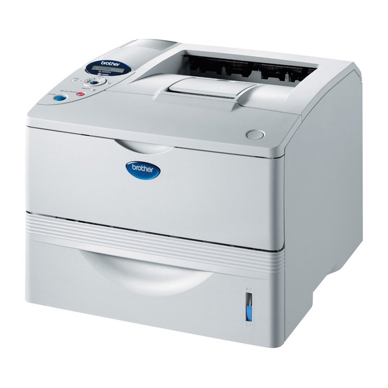
HL-6050/6050D/6050DN SERVICE MANUAL OVERVIEW <Front View> Support Flap Face down output tray Control Panel MP Tray Front Cover Front Cover Release Button MP Tray Support Flap Paper Tray Fig. 1-1 <Rear View> (HL-6050DN) Network Test Button Compact Flash Card Slot... -
Page 18: Specifications
CHAPTER 1 GENERAL SPECIFICATIONS Printing Print method Electrophotography by semiconductor laser-beam scanning Laser Wavelength: 780 nm Pulse duration 20 ns Output: 10mW max ® ® ® Resolution 1200dpi (for Windows 95/98/Me, WindowsNT 4.0, Windows 2000/XP, and Mac OS, Linux) ® ®... -
Page 19: Functions
HL-6050/6050D/6050DN SERVICE MANUAL Functions Fujitsu SPARClite 200MHz Emulation Brother Printing Solution for Windows Automatic emulation selection among HP LaserJet (PCL level 6), Brother BR-Script Level 3, EPSON FX-850 or IBM Proprinter XL Printer driver <PCL Driver> Windows 95/98/Me, Windows NT 4.0, Windows®... -
Page 20: Electrical And Mechanical
90 W or less at 25°C (77°F) Sleep*: 10 W or less (For HL-6050DN), 8 W or less (For HL-6050 and HL-6050D) 2 W or less (The only way to achieve 0 W power consumption is to unplug the power cord from the AC outlet/ socket.) -
Page 21: Network (Nc-6100H)
• Web Based Management Firmware update Flash ROM based for Network module • Can be upgraded using TFTP • Can be upgraded using IPX/SPX • Easy upgrade using Brother BRAdmin utility • BRAdmin Professional management utility (for Windows Supplied software 95/98/Me ... -
Page 22: Paper
CHAPTER 1 GENERAL Paper 3.5.1 Feedable paper (1) Paper type Multi- Automatic Select the paper Optional Paper tray Paper type purpose Duplex type from the (standard) lower tray tray printing printer driver Plain paper Plain paper 60 g/m to 105 g/m (16 to 28 lb) Recycled paper Recycled paper... - Page 23 HL-6050/6050D/6050DN SERVICE MANUAL (2) Paper size Automatic Paper Tray Multi-purpose Optional lower Duplex (Standard) tray tray printing A4, Letter, Legal, B5 Width: A4, Letter, A4, Letter, (ISO), A5, B6 (ISO), 69.9 to 215.9 Legal, B5 (ISO), Legal A6, Executive, Folio A5, B6 (ISO), (2.75 to 8.5 in.)
-
Page 24: Paper Tray Capacity
CHAPTER 1 GENERAL • It is recommended to use labels or transparencies which are designed for use in laser printers. • Avoid feeding labels with the carrier sheet exposed, or the printer will be damaged. • Before loading paper with holes such as organizer sheets, be sure to fan the stack well. •... - Page 25 HL-6050/6050D/6050DN SERVICE MANUAL Printable Area 3.6.1 PCL5e/EPSON/IBM emulation When using PCL emulation, the edges of the paper that cannot be printed on are shown below. Physical page Printable area Logical page Physical page length Maximum logical page length Distance from edge of physical page to edge of logical page NOTE: “Logical page” shows the printable area for a PCL driver.
- Page 26 CHAPTER 1 GENERAL The table below shows the printable areas when printing on Portrait for each paper size. Size 215.9 mm 279.4 mm 203.2 mm 279.4 mm 6.35 mm 4.2 mm 8.5” 11.0” 8.0” 11.0” 0.25” 0 mm 0.16” Letter (2,550 dots) (3,300 dots) (2,400 dots)
- Page 27 HL-6050/6050D/6050DN SERVICE MANUAL Physical page Printable area Logical page Physical page length Maximum logical page length Distance from edge of physical page to edge of logical page NOTE: “Logical page” shows the printable area for a PCL driver. “Printable area” shows mechanical printable area of the machine. Therefore, the machine can only print within the shaded area when you use a PCL driver.
- Page 28 CHAPTER 1 GENERAL The table below shows the printable areas when printing on Landscape for each paper size. Size 279.4 mm 215.9 mm 269.3 mm 215.9 mm 5.0 mm 4.2 mm 11.0” 8.5” 10.6” 8.5” 0.2” 0 mm 0.16” Letter (3,300 dots) (2,550 dots) (3,180 dots)
-
Page 29: Print Speeds With Various Settings
HL-6050/6050D/6050DN SERVICE MANUAL Print Speeds with Various Settings Print speed of the HL-6050/6050D/6050DN printers is up to 24/25 ppm when loading A4 or Letter size paper from the paper tray in the plain paper mode. Actual print speed varies depending on the media type or paper size as shown in the tables below;... -
Page 30: Toner Cartridge Weight Information
CHAPTER 1 GENERAL Toner Cartridge Weight Information Toner Cartridge Weight (approx weight) TN4100/TN670 Brand new Toner Cartridge Weight 918g Toner Weight at Brand New Toner Cartridge 222.5±2.5g Toner Cartridge Weight at Toner Near Empty 785.5g Remain Toner Weight at Toner Near Empty Toner Cartridge Weight at Toner Empty 775.5g Remain Toner Weight at Toner Empty... -
Page 31: Serial No. Descriptions
HL-6050/6050D/6050DN SERVICE MANUAL SERIAL NO. DESCRIPTIONS The descriptions below show how to understand the meanings of the numbers printed on the labels or bag of the printer and printer parts: < ID for production month > January February March April... - Page 32 CHAPTER 1 GENERAL (4) Toner cartridge: Imprinted on the aluminum bag 3 K 3 0 YEAR MONTH DATE FACTORY ID NO. Printed on the bar code label attached on the toner cartridge CARTRIDGE K 3 9 H 0 0 0 1 9 9 A PRODUCTION INFO.
-
Page 33: Chapter 2 Installation And Basic Operation
HL-6050/6050D/6050DN SERVICE MANUAL CHAPTER 2 INSTALLATION AND BASIC OPERATION CONDITIONS REQUIRED FOR INSTALLATION Power Supply • The source voltage must stay within ±10% of the rated voltage shown on the rating plate. • The power cord, including extensions, should not exceed 5 meters (16.5 feet). -
Page 34: System Requirements For Brother Printer Solution For Windows
CHAPTER 2 INSTALLATION AND BASIC OPERATION System Requirements for Brother Printer Solution for Windows Check the following system requirements to setup and operate the printer using Brother Printing Solution for Windows Computing System Processor Speed Minimum Recommended Available... -
Page 35: Unpacking
HL-6050/6050D/6050DN SERVICE MANUAL UNPACKING When unpacking the printer, check to see that all of the following components are included in the carton. Printer Drum Unit Assembly (with Toner Cartridge included) CD-ROM AC Power Cord Quick Setup Guide Fig. 2-1 NOTE: The power cord may be slightly different than the one shown in the figure above, depending on which country the printer was bought in. -
Page 36: Install The Printer
CHAPTER 2 INSTALLATION AND BASIC OPERATION INSTALL THE PRINTER You need to implement hardware setup and driver installation to use the printer. ® ® Firstly, identify the Operating System on your computer. (Windows 95/98/Me, Windows NT ® 4.0, Windows 2000/XP and Macintosh)Then, purchase the appropriate interface cable (Parallel, USB or Network) for your computer. -
Page 37: Install The Drum Unit Assembly
HL-6050/6050D/6050DN SERVICE MANUAL 3.1.1 Install the drum unit assembly (1) Open the front cover by pressing the front cover release button. (2) Unpack the drum unit assembly. Rock it from side to side several times to distribute the toner evenly inside the assembly. -
Page 38: Load Paper Into The Paper Tray
CHAPTER 2 INSTALLATION AND BASIC OPERATION 3.1.2 Load paper into the paper tray (1) Pull the paper tray completely out of the printer. (2) While pressing the paper guide release lever, slide the adjusters to fit the paper size. Check that the guides are firmly in the slots. Fig. -
Page 39: Print A Test Page
HL-6050/6050D/6050DN SERVICE MANUAL 3.1.3 Print a test page (1) Make sure the printer power switch is off. Connect the AC power cord to the printer. Do not connect the interface cable. Connecting the interface cable is done when installing the driver. -
Page 40: Control Panel Operation
CHAPTER 2 INSTALLATION AND BASIC OPERATION CONTROL PANEL OPERATION The printer has one LCD, seven buttons and one LED on the control panel. The LED and LCD display indicate the printer status, and pressing the switches enables several functions in the printer. -
Page 41: Panel Switches Functions
HL-6050/6050D/6050DN SERVICE MANUAL Panel Switches Functions You can control the basic printer operations and change various printer settings with 7 buttons (Go, Job Cancel, Reprint, +, -, Set, Back). Function Exit from the control panel menu, reprint settings and error messages. -
Page 42: Reprint Button
CHAPTER 2 INSTALLATION AND BASIC OPERATION 4.2.3 Reprint button If you want to reprint a document that has just been printed, you can reprint it by pressing the Reprint button. Also, if you have created a document that you wish to share with colleagues, simply spool the document to a non-secure area of the printer. - Page 43 HL-6050/6050D/6050DN SERVICE MANUAL Reprint the last job 3 times 1. Set the REPRINT setting is ON by using the control panel buttons to enter the SETUP menu. NOTE: If you print with the driver we have supplied with the printer, the settings for Job Spooling in the printer driver will take priority over the settings made on the control panel.
- Page 44 CHAPTER 2 INSTALLATION AND BASIC OPERATION Operations for printing secure data If there is no data. Press the Reprint switch. NO DATA STORED LAST JOB Press + or - SECURE FILE Press Set USER XXXXXXX Press + or – to select the user name. Press the Set button to set the user name.
- Page 45 HL-6050/6050D/6050DN SERVICE MANUAL (3) Printing Proof data You can use this setting to reprint Proof data that has been printed and has no security settings. Documents that are placed in the Proof area are available to anyone. You might use this setting for a document that will be moved to a public folder at a later date.
-
Page 46: Button
CHAPTER 2 INSTALLATION AND BASIC OPERATION 4.2.4 + & - button If you press the + or – button when the printer is in the on-line (READY), it goes off-line and the LCD displays the menu. (1) To move through menus on the LCD If you press the + or –... -
Page 47: Backlights
HL-6050/6050D/6050DN SERVICE MANUAL 4.3.1 Backlights The backlight of the LCD shows the current printer status with the different colors and the light indications (on, off and blinking). Signal Status The printer is power off or in sleep status. Warming up... -
Page 48: How To Use The Control Panel
CHAPTER 2 INSTALLATION AND BASIC OPERATION How to Use the Control Panel When you use the Menu buttons (+, –, Set or Back), remember the following basic steps: • If no control panel operations are performed for 30 seconds, the LCD automatically returns to READY. -
Page 49: Control Panel Setting Menu
HL-6050/6050D/6050DN SERVICE MANUAL Control Panel Setting Menu There are 8 modes. For more information about the selections available for each mode, refer to the pages listed below. INFORMATION For more information, see subsection 4.5.1 ‘INFORMATION’ in this Chapter. PAPER For more information, see subsection 4.5.2 ‘PAPER’... -
Page 50: Information
CHAPTER 2 INSTALLATION AND BASIC OPERATION 4.5.1 Information Display Shows Description Print the print settings page. PRINT SETTINGS Print the test page. PRINT TEST Print the demonstration sheet. PRINT DEMO Print the list of data saved in the CompactFlash card or in the embedded memory when the CompactFlash card has not been PRINT FILE LIST installed.. -
Page 51: Paper
HL-6050/6050D/6050DN SERVICE MANUAL 4.5.2 Paper Display Shows Description =AUTO / MP/ TRAY1 / TRAY2 * SOURCE Selects which paper tray the paper will be fed from. =MP>T1>T2 / T1>T2>MP / T1>T2 PRIORITY =ON / OFF MP FIRST Selects whether to feed paper from the MP tray as a priority. -
Page 52: Setup
CHAPTER 2 INSTALLATION AND BASIC OPERATION 4.5.4 Setup Display Shows Description =ENGLISH / FRANÇAIS / … LANGUAGE Sub-setting Description PANEL CONTROL =0/1/2 LCD DENSITY =ON/OFF AUTO ONLINE Sets the time for the display message BUTTON REPEAT to change when holding the + or – button at intervals of: 0.1, 0.2, 0.3, 0.4, 0.5, 1.0, 1.5 or 2.0 seconds. -
Page 53: Print Menu
HL-6050/6050D/6050DN SERVICE MANUAL Deletes the data in CompactFlash card. DELETE STORAGE Sub-setting Description Selects the user name, job name and SECURE FILE password. Selects the user name and job name. PUBLIC FILE Selects the user name and job name. PROOF FILE... - Page 54 CHAPTER 2 INSTALLATION AND BASIC OPERATION Sub-setting Description HP LASERJET =I000…#### FONT NO. FONT =##.## PITCH/POINT PC-8 / … SYMBOL SET Sets the symbol set or the character set. Prints code table TABLE PRINT =OFF / ON AUTO LF ON: CR CR+LF, OFF: CR CR =OFF / ON AUTO CR...
- Page 55 HL-6050/6050D/6050DN SERVICE MANUAL Sub-setting Description EPSON FX-850 =I000…#### FONT NO. FONT PITCH/ =##.## POINT PC-8 / … CHARACTER SET Sets the symbol set or the character set. Prints code table. TABLE PRINT =OFF / ON AUTO LF ON: CR CR+LF...
- Page 56 CHAPTER 2 INSTALLATION AND BASIC OPERATION Sub-setting Description IBM PROPRINTER =I000 … #### FONT NO. FONT =##.## PITCH/POINT PC-8 / … CHARACTER SET Sets the symbol set or the character set. Prints code table. TABLE PRINT =OFF / ON AUTO LF ON: CR CR+LF OFF: CR CR =OFF / ON...
-
Page 57: Network (Hl-6050Dn Only)
HL-6050/6050D/6050DN SERVICE MANUAL 4.5.6 Network (HL-6050DN only) Display Shows Description Sub-setting Description TCP/IP =ON / OFF TCP/IP ENABLE ###, ###, ###, ### IP ADDRESS= ###, ###, ###, ### SUBNET MASK= ###, ###, ###, ### GATEWAY= IP BOOT TRIES =AUTO / STATIC / RARP / BOOTP /... -
Page 58: Interface
CHAPTER 2 INSTALLATION AND BASIC OPERATION 4.5.7 Interface Setting Menu Description SELECT =ATUO / PARALLEL / USB / NETWORK AUTO IF TIME = 1, 2, 3 … 99 (sec) You need to set the time-out period for the auto interface selection. -
Page 59: Set Ip Address
HL-6050/6050D/6050DN SERVICE MANUAL 4.5.9 Set IP address INFORMATION Press the + or – button until NETWORK appears (and to display each setting shown below.) NETWORK Press the Set button. TCP/IP Press the Set button. TCP/IP ENABLE Press the + button. -
Page 60: 4.5.10 About Emulation Modes
CHAPTER 2 INSTALLATION AND BASIC OPERATION 4.5.10 About emulation modes This printer has the following emulation modes. HP LserJet Mode The HP LaserJet mode (or HP mode) is the emulation mode in which this printer supports the PCL6 language of the Hewlett-Packard LaserJet laser printer. Many software applications support this type of laser printer. - Page 61 HL-6050/6050D/6050DN SERVICE MANUAL Mode Menu Factory Setting =AUTO PAPER SOURCE =MP>T1>T2 PRIORITY =OFF MP FIRST =ANY MP SIZE =OFF MANUAL FEED =DETECT SENSOR TRAY1 SIZE =DETECT SENSOR TRAY2 SIZE =OFF DUPLEX =600 QUALITY RESOLUTION =MEDIUM =OFF TONER SAVE DENSITY =ENGLISH...
- Page 62 CHAPTER 2 INSTALLATION AND BASIC OPERATION Mode Menu Factory Setting =PLAIN PAPER PRINT MENU MEDIA TYPE =A4 / LETTER PAPER COPIES =PORTRAIT ORIENTATION Subsetting Factory setting PRINT POSITION X OFFSET Y OFFSET AUTO FF TIME =OFF FF SUPPRESS Subsetting Factory setting HP LASER JET FONT NO.
- Page 63 HL-6050/6050D/6050DN SERVICE MANUAL Mode Menu Factory Setting Subsetting Factory setting PRINT MENU IBM PROPRINTER (Continued) FONT NO. =I059 FONT PITCH =10.00 / 12.00 SYMBOL SET =PC-8 AUTO LF =OFF AUTO CR =OFF LEFT MARGIN =#### RIGHT MARGIN =#### TOP MARGIN...
-
Page 64: Other Control Features
CHAPTER 2 INSTALLATION AND BASIC OPERATION Mode Menu Factory Setting INTERFACE SELECT =AUTO AUTO IF TIME INPUT BUFFER =LEVEL 3 PARALLEL Subsetting Factory setting HIGH SPEED BI-DIR INPUT PRIME =OFF USB 2.0 HIGH SPEED *1 Automatic Private IP Addressing (APIPA) protocol automatically configures an IP address and subnet mask. -
Page 65: Network Board Operation
HL-6050/6050D/6050DN SERVICE MANUAL NETWORK BOARD OPERATION Installing the Brother network board (NC-6100h) allows you to connect the printer on a network running TCP/IP, IPX/SPX, AppleTalk, DLC/LLC and NetBEUI protocols. Many useful features, such as BRAdmin Professional for the administrator and Brother network printing software, are included on the CD-ROM supplied with this printer. - Page 66 CHAPTER 2 INSTALLATION AND BASIC OPERATION (5) Put the network board connector firmly into the connector of the main controller board by aligning the two screws to the groove of the printer, and then secure it with the two screws. Fig.
-
Page 67: Functions
HL-6050/6050D/6050DN SERVICE MANUAL Functions 5.2.1 LED functions Link/Speed LED Active LED Fig. 2-15 No light: If both of the two LEDs are off, then the print server is not connected to the network. Link/Speed LED is orange: Fast Ethernet Link/Speed LED is green: 10 Base T Ethernet This Link/Speed LED will be orange if the print server is connected to a 100BaseTX Fast Ethernet network. -
Page 68: Paper Tray Information (For Europe Only)
Cutting position Fig. 2- 16 (3) If the optional LT-6000 Lower Tray Unit is installed onto the HL-6050/6050D/6050DN printer, it is necessary to exchange the tray supplied with the LT-6000 Unit with the upper tray already fitted into the printer. Install the tray originally fitted in the printer into the LT- 6000 Unit. -
Page 69: Chapter 3 Theory Of Operation
HL-6050/6050D/6050DN SERVICE MANUAL CHAPTER 3 THEORY OF OPERATION ELECTRONICS General Block Diagram Fig. 3-1 shows a general block diagram. NC-6100h Ethernet RAM (DIMM)(max. 128MB) 10/100 Base TX Control system Expansion AIO I/F memory I/O RAM: 32MB Interface block (Parallel / USB) -
Page 70: Main Pcb Block Diagram
CHAPTER 3 THEORY OF OPERATION Main PCB Block Diagram Fig. 3-2 shows the block diagram of the main PCB. A S I C CPU Core (SPARClite 200MHz) Oscillator 66.6MHz Reset Circuit Address Decoder DRAM Control Boot + Font ROM (8 MB) Timer Main Program (3 MB) STRAGE (1 MB) -
Page 71: Main Pcb
HL-6050/6050D/6050DN SERVICE MANUAL Main PCB For the entire circuit diagram of the main PCB, see APPENDIX 1. to 6. ‘MAIN PCB CIRCUIT DIAGRAM’ in this manual. 1.3.1 A Fujitsu 32bit RISC CPU, SPARClite is built in the ASIC. While the CPU is driven with a clock frequency of 66.66 MHz in the user logic block, it itself runs at 200 MHz, which is... -
Page 72: Usb
CHAPTER 3 THEORY OF OPERATION The functions of the interface block communication with external devices are described below; 1.3.2 Stores the data received from the PC into DRAM as controlled by the DMA controller. The transmission speed is 480Mbps or 12Mbps. CN12 TP237 R167... -
Page 73: Network Interface
HL-6050/6050D/6050DN SERVICE MANUAL 1.3.4 Network Interface The network supports 10 Base-T/100 Base-TX through NC-6100h connected via AIO Interface. NC-6100h and HL-6050DN are standard, 6050D, 6050 are optional. ADR_M[2] ADR_M[3] ADR_M[4] ADR_M[5] ADR_M[6] ADR_M[7] ADR_M[8] ADR_M[9] ADR_M[10] ADR_M[11] ADR_M[12] ADR_M[13] ADR[14]... -
Page 74: Rom
CHAPTER 3 THEORY OF OPERATION 1.3.5 A 64Mbit ROM (x 16bit) is fitted. MASK ROM (128/64Mbit) ADR[22] ADR[23] ROMCSN0 VCC-37 VDD3 1-5C/3C VCC-38 IORDN VSS-12 1-5C/2C/3C/7C/6-2E VSS-25 VSS-26 VDD3 VSS-36 VSS-47 VSS-48 ADR[1] ADR[2] ADR[3] ADR[4] ADR[5] DATA[0] ADR[6] DATA[1] ADR[7] DATA[2] ADR[8]... -
Page 75: Flash Rom
HL-6050/6050D/6050DN SERVICE MANUAL 1.3.6 Flash ROM A 32Mbit flash ROM (x 16bit) is fitted. FOR PATCH ADR[22] ROMCSN1 VDD3 1-5C IOWEN 1-5C/3C/7C/6-2E IORDN VSS27 C103 1-5C/3C/5D/7C/6-2E RY/BY VSS46 ADR[20] TP119 R110 BYTE VDD3 VDD3 RESET TP118 R107 R108 ADR[1] C104... -
Page 76: Sdram
CHAPTER 3 THEORY OF OPERATION 1.3.7 SDRAM A 256Mbit SDRAM (x 16bit) is used as the RAM. SDRAM SDCSN0 VDD1 VDD3 1-5C RASN ADR[17] VDD14 1-6A/3-1E/3-3C/3-4D/1C/1E/6B CASN ADR[18] VDD27 1-6A/3-1E/3-3C/3-4D/1C/1E/6B VDDQ3 ADR[19] 1-6A/3-1E/3-3C/3-4D/1C/1E/6B VDDQ9 DQM0 ADR[20] LDQM VDDQ43 1-6A/3-1E/3-3C/3-4D/1C/1E/6B DQM1 ADR[21] UDQM VDDQ49... -
Page 77: Optional Ram
HL-6050/6050D/6050DN SERVICE MANUAL 1.3.8 Optional RAM A 32bit (100 pin) DIMM can be fitted as optional RAM. The main PCB has one slot and the capacity of DIMM can be from 16MB to 128MB. DATA_D[15-0] DIMM DATA_D[0] VDD3 DATA_D[1] DATA_D[2]... -
Page 78: Compact Flash
CHAPTER 3 THEORY OF OPERATION 1.3.9 Compact Flash Compact Flash is controlled by Media GA connected to ASIC. IBM's microdrive is not supported due to it's high actuating current. MEDIA GA 33.868MHz TP89 MEDIA GA COMPACT FLASH XOUT CF_AD[0-10] CN11 CF_AD[0-10] TP88 TP176... -
Page 79: 1.3.11 Reset Circuit
HL-6050/6050D/6050DN SERVICE MANUAL 1.3.11 Reset Circuit The reset IC is a R3112N281C. The reset voltage is 2.8V (typ.) and the LOW period of reset is 22.4ms (typ.) VDD3 C136 C103 C137 C103 R172 TP258 TP259 VOUT R3112N281C C138 TP247 C101... -
Page 80: 1.3.14 Video I/O
CHAPTER 3 THEORY OF OPERATION 1.3.14 Video I/O The video signal output from the ASIC is reversed through a transistor and output after being corrected by the buffer IC. VDD3 0 (1608) TP10 FEEDBACK FEEDBACK TP41 6-6C TP42 TP33 2-1D DATA1 DATA1-1 TP34... -
Page 81: 1.3.15 Sensor I/O
HL-6050/6050D/6050DN SERVICE MANUAL 1.3.15 Sensor I/O Each sensor of Pre-Regist, Regist, T1-PE, Plate, MP-PE, DX-Size, DX-Jam, Rear tray, Front cover, and DEV is connected to ASIC port on the main PC board and to be read with a software. VDD3... -
Page 82: Engine Pcb
Lower tray plate sensor • For the circuit diagram of the engine PCB, see APPENDIX 11. and 12. ‘ENGINE PCB CIRCUIT DIAGRAM’ in this manual. Sensor configuration varies according to machine types. HL-6050 HL-6050D/DN DX-SENSOR DX-SOLENOID : Built-in : Not built-in 3-14... -
Page 83: Power Supply
HL-6050/6050D/6050DN SERVICE MANUAL Power Supply 1.5.1 Low-voltage power supply The power supply uses a switching regulation system to generate the regulated DC power (+3.3V, +8V [non regulated] and +24V), which are converted from the AC line. The regulated output and the production code of each power supply are listed below;... -
Page 84: In This Manual
CHAPTER 3 THEORY OF OPERATION 1.5.2 High-voltage power supply The high-voltage power supply generates and outputs the voltages and currents for the charging, development and transfer functions. For the circuit diagram of the high-voltage power supply PCB, see APPENDIX 10. ‘HIGH- VOLTAGE POWER SUPPLY CIRCUIT DIAGRAM’... -
Page 86: Paper Transfer
CHAPTER 3 THEORY OF OPERATION Paper Transfer 2.2.1 Paper supply The paper pick-up roller picks up one sheet of paper from the paper tray every time it is rotated and feeds it to the paper feed roller. F roller AML MP Paper pick-up roller Paper feed pinch roller RE roller... -
Page 87: Paper Particle Remover Unit
2.2.3 Paper particle remover unit HL-6050 series printer has a paper particle remover unit to remove paper particles (dust) from the surface of the paper, thus minimizing any paper particles (dust) in the drum. A. When the paper is fed from the paper tray: 1. -
Page 88: Paper Registration
CHAPTER 3 THEORY OF OPERATION 2.2.4 Paper registration After the paper top position is detected by the regist front actuator, the paper, separated into individual sheets by the paper pick-up roller, is fed further for a specified time, and the paper top position reaches the paper feed roller so that the paper skew is adjusted. -
Page 89: Paper Eject
HL-6050/6050D/6050DN SERVICE MANUAL 2.2.5 Paper eject After the printing image on the photosensitive drum is transferred onto the paper, the paper is fed to the fixing unit to fix unfixed toner onto the paper. Afterwards, the paper is ejected from the fixing unit by the first eject roller in the fixing unit. -
Page 90: Sensors
CHAPTER 3 THEORY OF OPERATION Sensors 2.3.1 Document cover sensor Document cover sensor Exit roller unit Fig. 3-26 2.3.2 Fixing sensor PCB ASSY Fixing unit Fixing sensor PCB ASSY Fig. 3-27 3-22... -
Page 91: Photo Interrupter
HL-6050/6050D/6050DN SERVICE MANUAL 2.3.3 Photo interrupter Photo interrupter Fig. 3-28 2.3.4 Toner sensor PCB unit / Toner LED PCB ASSY Toner sensor PCB unit Toner LED PCB ASSY Fig. 3-29 3-23... -
Page 92: Relay Pcb Unit
CHAPTER 3 THEORY OF OPERATION 2.3.5 Relay PCB unit Relay PCB unit Fig. 3-30 2.3.6 PE/PO sensor PCB ASSY PE/PO sensor PCB ASSY Fig. 3-31 3-24... -
Page 93: Dev Sensor Assy
HL-6050/6050D/6050DN SERVICE MANUAL 2.3.7 DEV sensor ASSY DEV sensor ASSY Fig. 3-32 2.3.8 MP sensor PCB ASSY MP chute MP sensor PCB ASSY Fig. 3-33 3-25... -
Page 94: Drum Unit
CHAPTER 3 THEORY OF OPERATION Drum Unit 2.4.1 Photosensitive drum Generates the latent electrostatic image and develops the image on the drum surface. 2.4.2 Primary charger Forms a uniform charge on the drum surface. (1) Corona wire Generates the ion charge on the drum. (2) Grid Spreads the ion charge evenly over the drum surface. -
Page 95: Toner Cartridge
HL-6050/6050D/6050DN SERVICE MANUAL Toner Cartridge Develops the electrostatic latent image on the photosensitive drum with toner and forms the visible image. 2.5.1 Toner empty mode The life of the toner cartridge is 7,500 pages at the 5% coverage. In the case of low-duty printing, however, “TONER EMPTY”... -
Page 96: New Toner Detection Boss
CHAPTER 3 THEORY OF OPERATION 2.5.2 New toner detection boss To prevent the toner leakage and image quality degradation when printing in a low duty, HL- 6050 has the function to detect when the new toner is installed. (If the toner is used beyond its life when printing in low duty, image defect or toner leakage may occur.) Install the toner cartridge (brand-new) into the drum unit, then install it into the printer. -
Page 97: Print Process
Fig. 3-36 <Laser exposure unit> The HL-6050 series printer has a twin laser beam unit to get a resolution of 1200 dpi x 1200 dpi at full-speed printing (A4/LETTER: 24/25 ppm). 1. The two laser beams radiated from a laser diode inside the laser unit are concentrated into a constant width by a slit in the CO lens cell and then reflected by a polygon mirror rotating at high speed. - Page 98 CHAPTER 3 THEORY OF OPERATION 2. The two laser beams reflected by the polygon mirror are refracted by the theta lens and radiated from the right through to the left end of the reflection mirror as the polygon mirror rotates. At this time, blur of the vertical direction of the laser beam by inclination of a polygon mirror is corrected by passing a CYL lens.
-
Page 99: Pressure Contact And Release Unit
2.6.3 Pressure contact and release unit HL-6050 series printer has the pressure contact and release unit of the development roller. In order to lengthen the service life of the toner unit, development roller of the toner unit is brought into close contact with the photosensitive drum when necessary. -
Page 100: Transfer
CHAPTER 3 THEORY OF OPERATION 2.6.5 Transfer (1) Transfer process After the drum has been charged and exposed, and has received a developed image, the toner formed is transferred onto the paper by applying a negative charge to the back of the paper. -
Page 101: Chapter 4 Disassembly And Re-Assembly
HL-6050/6050D/6050DN SERVICE MANUAL CHAPTER 4 DISASSEMBLY AND RE-ASSEMBLY SAFETY PRECAUTIONS To avoid creating secondary problems by mishandling, follow the warnings and precautions below during maintenance work. WARNING (1) Always turn off the power switch and unplug the power cord from the power outlet before accessing any parts inside the printer. -
Page 103: Disassembly Procedure
HL-6050/6050D/6050DN SERVICE MANUAL DISASSEMBLY PROCEDURE AC Cord (1) Disconnect the AC cord from the printer. Printer AC cord Fig. 4-1 Drum Unit (1) Open the process unit cover ASSY and remove the drum unit. Drum unit Process unit cover ASSY... -
Page 104: Paper Tray
CHAPTER 4 DISASSEMBLY AND RE-ASSEMBLY Paper Tray (1) Close the process unit cover ASSY and pull out the paper tray. (2) Remove the paper from the paper tray. Process unit cover ASSY Paper tray Fig. 4-3 (3) Remove the separation pad ASSY and the separation pad spring from the paper tray. NOTE: Be sure not to lose the separation pad spring when you remove the separation pad ASSY. - Page 105 HL-6050/6050D/6050DN SERVICE MANUAL (4) Remove the two cup B M3x8 Taptite screws, and remove the paper tray cover. Paper tray cover Taptite, cup B M3x8 Paper tray Fig. 4-5 (5) Remove the “A” portion of the roller holder spring. (6) Remove the P roller unit.
- Page 106 CHAPTER 4 DISASSEMBLY AND RE-ASSEMBLY (7) Remove the four bind B M4x10 Taptite screws. (8) Remove the four hooks with lifting pressure plate, and remove the front tray 1 from the paper tray. Hooks Paper indicator Pressure plate Taptite, bind B M4x10 Paper tray Pins Taptite, bind B M4x10...
-
Page 107: Access Cover
HL-6050/6050D/6050DN SERVICE MANUAL Access Cover (1) Remove the access cover. Access cover Fig. 4-9 Network Board (1) Remove the main PCB access plate. (2) Loosen the two access cover screws, and remove the network board. Main PCB Main PCB access plate... -
Page 108: Dx Feed Assy
CHAPTER 4 DISASSEMBLY AND RE-ASSEMBLY DX Feed ASSY (1) Remove the DX feed ASSY from the printer. DX feed ASSY Fig. 4-11 (2) Remove the bind B M3x4 screw, and remove the ground wire cover and ground wire. (3) Remove the bind B M3x7.5A Taptite shoulder screw and bind B M3x8 Taptite screw, and remove the paper guide upper ASSY. - Page 109 HL-6050/6050D/6050DN SERVICE MANUAL (4) Remove the roller holder from the paper guide upper ASSY HE. (5) Remove the pressure roller from the roller holder. Bosses Roller holder Pressure roller Paper guide upper ASSY HE Fig. 4-13 (6) Remove the bind B M3x5 Taptite screw, and remove the side regist roller holder.
- Page 110 CHAPTER 4 DISASSEMBLY AND RE-ASSEMBLY NOTE: Be sure that both boss and pin are inserted before mounting the side regist roller holder. Side regist roller holder Boss Left guide plate ASSY Fig. 4-15 (8) Remove the two bind B M3x8 Taptite screws, and remove the two guide plate stopper. (9) Remove the two left guide spring 2 from the DX feed ASSY.
- Page 111 HL-6050/6050D/6050DN SERVICE MANUAL (11) Remove the left guide plate ASSY from the DX feed ASSY. (12) Remove the drive gear 14 from the DX feed ASSY. (13) Remove the DX feed roller ASSY from the DX feed ASSY. DX feed roller ASSY...
-
Page 112: Rear Cover Assy
CHAPTER 4 DISASSEMBLY AND RE-ASSEMBLY (16) Remove the two side regist roller from the DX feed ASSY. (17) Remove the T-belt B40S2M142 from the DX feed ASSY. (18) Remove the T-belt B40S2M224 from the DX feed ASSY. DX feed ASSY Side regist roller T-belt B40S2M224 T-belt B40S2M142... -
Page 113: Top Cover Assy
HL-6050/6050D/6050DN SERVICE MANUAL Top Cover ASSY (1) Open the process unit cover ASSY. (2) Remove the two shoulder screws at the front and another two at the rear. (3) Remove the top cover ASSY as removing the connector of the panel harness ASSY. - Page 114 CHAPTER 4 DISASSEMBLY AND RE-ASSEMBLY (5) Remove the three cup B M3x8 Taptite screws, and remove the panel PCB ASSY. (6) Disconnect the connector of back light PCB harness and LCD harness from the panel PCB ASSY. Taptite, cup B M3x8 Panel PCB ASSY Back light PCB harness LCD harness...
-
Page 115: Side Cover L
HL-6050/6050D/6050DN SERVICE MANUAL (8) Release the two hooks “A”, and remove the back light PCB ASSY. (9) Release the two hooks “B”, and remove the LCD. Back light PCB ASSY Hooks “A” LCD holder Hooks “B” Diffusion film Fig. 4-25 Side Cover L (1) Remove the two shoulder screws. -
Page 116: Side Cover R
CHAPTER 4 DISASSEMBLY AND RE-ASSEMBLY 3.10 Side Cover R (1) Remove the shoulder screw. (2) Release the three hooks, and remove the side cover R. Hooks Hook Side cover R Hooks Shoulder screw Fig. 4-27 3.11 MP Paper Guide 1 ASSY (1) Remove the MP paper guide 1 ASSY. -
Page 117: Process Unit Cover Assy / Mp Cover Assy
HL-6050/6050D/6050DN SERVICE MANUAL 3.12 Process Unit Cover ASSY / MP Cover ASSY (1) Remove the two cover stopper rings. (2) Remove the arm on both sides from the process unit cover ASSY. (3) Loosen the screw, and remove the process unit cover ASSY and MP cover ASSY. -
Page 118: Exit Roller Unit
CHAPTER 4 DISASSEMBLY AND RE-ASSEMBLY 3.13 Exit Roller Unit (1) Disconnect the connector “A” from the relay PCB L ASSY. (2) Disconnect the connector “B” from the relay PCB R ASSY. (3) Remove the two cup S M3x6 Taptite screws, and remove the exit roll unit. Taptite, cup S M3x6 Taptite, cup S M3x6 Connector “A”... - Page 119 HL-6050/6050D/6050DN SERVICE MANUAL (6) Release the four hooks, and remove the exit roller cover. (7) Remove the paper upper guide. Hook Exit roller cover Hook Hook Hook Paper upper guide Exit roller frame Fig. 4-33 4-19...
-
Page 120: Laser Unit
CHAPTER 4 DISASSEMBLY AND RE-ASSEMBLY 3.14 Laser Unit (1) Disconnect the connector and flat cable. (2) Remove the four cup S M3x16 Taptite screws, and remove the laser unit. Taptite, cup S M3x16 Taptite, cup S M3x16 Laser unit Flat cable Connector Relay PCB L ASSY Fig. -
Page 121: Fixing Unit
HL-6050/6050D/6050DN SERVICE MANUAL 3.15 Fixing Unit NOTE: When replacing the fixing unit, be sure to wait 30 minutes or more after turning off the power because its front side is heated. (1) Disconnect the two connectors. (2) Remove the two cup S M3x6 Taptite screws, and remove the fixing unit. - Page 122 CHAPTER 4 DISASSEMBLY AND RE-ASSEMBLY (4) Remove the two pan (S/P washer) M3x8 screws, and remove the thermostat 1. (5) Remove the two pan (S/P washer) M3x8 screws, and remove the thermostat 2. Screw, pan (S/P washer) M3x8 Thermostat 1 Thermostat 2 Fuser cover upper Fig.
- Page 123 HL-6050/6050D/6050DN SERVICE MANUAL (8) Remove the two pan (S/P washer) M3x8 screws. (9) Remove the halogen heater 115S. Screw, pan (S/P washer) M3x8 Screw, pan (S/P washer) M3x8 Halogen heater 115S Fixing unit Fig. 4-40 (10) Remove the bind M3x8 screw, and remove the thermistor C.
- Page 124 CHAPTER 4 DISASSEMBLY AND RE-ASSEMBLY (11) Push down the envelop lever R and the envelop lever L. Envelop lever R Envelop lever L Fixing unit Fig. 4-42 (12) Remove the two bind S M3x6 Taptite screws, and remove the side cover L. (13) Remove the two bind S M3x6 Taptite screws, and remove the side cover R.
- Page 125 HL-6050/6050D/6050DN SERVICE MANUAL (14) Remove the heat roller gear 30. (15) Remove the two bind S M3x6 Taptite screws, and remove the gear plate ASSY. Fixing unit Taptite, bind S M3x6 Gear plate ASSY Taptite, bind S M3x6 Heat roller gear 30 Fig.
- Page 126 CHAPTER 4 DISASSEMBLY AND RE-ASSEMBLY (17) Remove the four bind S M3x6 Taptite screws, and remove the HR hold plate. (18) Remove the HR ring. Fixing unit Taptite, bind S M3x6 HR ring HR hold plate Taptite, bind S HR hold plate M3x6 Fig.
- Page 127 HL-6050/6050D/6050DN SERVICE MANUAL (20) Release the three hooks, and remove the front shoot. Main frame Front shoot Hooks Fig. 4-48 (21) Remove the pressure roller 30. (22) Remove the two PR ball bearings from the pressure roller 30. PR ball bearing...
- Page 128 CHAPTER 4 DISASSEMBLY AND RE-ASSEMBLY (23) Release the hook, and remove the eject gear T. (24) Release the hook, and remove the release cam. (25) Remove the bearing 08. (26) Remove the collar 8, and remove the bearing 08. Collar 08 Main frame Eject gear T Bearing 08...
- Page 129 HL-6050/6050D/6050DN SERVICE MANUAL (28) Remove the collar 8, and move the release lever, the envelope lever L, and the envelope lever spring toward inside. Fixing unit Collar 08 Release lever Envelope lever spring Envelope lever L Lever shaft Fig. 4-52 (29) Remove the lever shaft.
- Page 130 CHAPTER 4 DISASSEMBLY AND RE-ASSEMBLY (30) Remove the two open cover springs. (31) Release the two hooks and two pins, and remove the open cover. Fixing unit Hook Open cover Hook Open cover springs Fig. 4-54 (32) Disconnect the connector of the thermistor C. (33) Remove the bind M3x4 screw, and remove the fixing sensor PCB ASSY.
- Page 131 HL-6050/6050D/6050DN SERVICE MANUAL (34) Release the hook and remove the eject roller gear 14 and eject roller bearing (L). (35) Release the hook and remove the eject roller gear 14 and eject roller bearing (R). (36) Remove the eject roller ASSY.
-
Page 132: Separation Roller Assy / Feed Roller Assy
CHAPTER 4 DISASSEMBLY AND RE-ASSEMBLY NOTE: Mount the sensor spring as shown in Fig. 4-58 when assembling the fixing sensor actuator. Fixing sensor actuator Open cover Fig. 4-58 3.16 Separation Roller ASSY / Feed Roller ASSY (1) Release the hook, and remove the separation roller ASSY. (2) Release the hook, and remove the feed roller ASSY. -
Page 133: Feed Mp Unit
HL-6050/6050D/6050DN SERVICE MANUAL 3.17 Feed MP Unit (1) Open the MP roller cover. (2) Remove the bearing R. (3) Remove the paper pick-up roller ASSY and roller collar. (4) Remove the bearing L. Roller collar Roller collar Bearing L Paper pick-up roller ASSY... -
Page 134: Fan Motor 80 Assy
CHAPTER 4 DISASSEMBLY AND RE-ASSEMBLY 3.18 Fan Motor 80 ASSY (1) Disconnect the connector from the engine PCB. (2) Remove the two cup S M3x6 Taptite screws, and remove the fan motor 80 unit. Fan motor 80 unit Taptite, cup S M3x6 Engine PCB Fig. -
Page 135: Filter
HL-6050/6050D/6050DN SERVICE MANUAL 3.19 Filter (1) Remove the two bosses, and remove the main duct. (2) Remove the filter from the main duct. Filter Boss Main duct Boss Fig. 4-64 3.20 Engine PCB (1) Disconnect the all connectors. (2) Remove the three cup S M3x6 Taptite screws, and remove the engine PCB. -
Page 136: Main Pcb
CHAPTER 4 DISASSEMBLY AND RE-ASSEMBLY 3.21 Main PCB (1) Disconnect the all connectors. (2) Remove the four cup S M3x6 Taptite screws and three screws, and remove the main PCB. Main PCB Taptite, cup S M3x6 Screws Taptite, cup S M3x6 Fig. -
Page 137: Lvps
HL-6050/6050D/6050DN SERVICE MANUAL 3.23 LVPS (1) Remove the four cup S M3x6 Taptite screws, and remove the main IF plate. (2) Pull out the connector from the connector blacket. (3) Remove the pan (washer) M3.5x6 screws, and remove the ground wire. - Page 138 CHAPTER 4 DISASSEMBLY AND RE-ASSEMBLY (6) Remove four screws, LVPS cover, and LVPS PCB. Screw LVPS PCB LVPS cover Fig. 4-70 4-38...
-
Page 139: Photo Interrupter
HL-6050/6050D/6050DN SERVICE MANUAL 3.24 Photo Interrupter (1) Disconnect the connector, and remove the photo interrupter. Connector Photo interrupter Fig. 4-71 3.25 T1 Solenoid ASSY / MP Solenoid ASSY (1) Remove the two cup S M3x6 Taptite screws, and remove the feeding gear plate unit. - Page 140 CHAPTER 4 DISASSEMBLY AND RE-ASSEMBLY (4) Release the two hooks, and remove the T1 solenoid lever. (5) Remove the solenoid spring MP. (6) Remove the flanged M3x3.5 screw. (7) Release the hook, and remove the T1 solenoid ASSY. (red) solenoid spring MP T1 solenoid ASSY T1 solenoid lever Hooks...
-
Page 141: Clutch Spring Separating
HL-6050/6050D/6050DN SERVICE MANUAL 3.26 Clutch Spring Separating (1) Release the hook, and remove the separating disk. (2) Remove the collar 6, and remove the clutch spring separating. Clutch spring separating Collar 6 Separating disk Hook Fig. 4-75 3.27 Magnetic Clutch Regist / Collar 6 (1) Remove the two cup S M3x6 Taptite screws, and remove the harness guard. -
Page 142: Main Motor
CHAPTER 4 DISASSEMBLY AND RE-ASSEMBLY 3.28 Main Motor (1) Remove the five cup S M3x6 Taptite screws, and remove the main gear plate ASSY. Main gear plate ASSY Taptite, cup S M3x6 Fig. 4-77 (2) Remove the five cup S M3x6 Taptite screws, and remove the main motor ASSY. (3) Release the hook, and remove the gear 23/36. -
Page 143: Developer Clutch
HL-6050/6050D/6050DN SERVICE MANUAL 3.29 Developer Clutch (1) Remove the collar 4 and bearing 4, and remove the developer clutch. Developer clutch Bearing 4 Collar 4 Main gear plate ASSY Fig. 4-79 3.30 Develop Joint (1) Remove the develop joint. (2) Remove the joint stopper from the develop joint. -
Page 144: Interlock Sw Assy
CHAPTER 4 DISASSEMBLY AND RE-ASSEMBLY 3.31 Interlock SW ASSY (1) Disconnect the connector. (2) Release the two hooks, and remove the interlock SW ASSY. Relay PCB L ASSY Hooks Interlock SW ASSY Fig. 4-81 3.32 Relay PCB L ASSY (1) Disconnect the all connectors. (2) Remove the cup S M3x6 Taptite screw, and remove the relay PCB L ASSY. -
Page 145: Dev Sensor Assy
HL-6050/6050D/6050DN SERVICE MANUAL 3.33 DEV Sensor ASSY (1) Release the hook, and remove the DEV switch holder. (2) Release the hook, and remove the DEV sensor ASSY. Hook DEV sensor ASSY Hook DEV switch holder Fig. 4-83 3.34 Toner LED PCB ASSY (1) Match the hook “A”... -
Page 146: Gear 18/48 / Gear Collar
CHAPTER 4 DISASSEMBLY AND RE-ASSEMBLY 3.35 Gear 18/48 / Gear Collar (1) Remove the two cup S M3x6 Taptite screws, and remove the fixing drive plate unit. (2) Remove the gear collar from the fixing drive plate unit, and remove the gear 18/48. Gear collar Gear 18/48 Taptite, cup S M3x6... -
Page 147: Plate Motor Assy
HL-6050/6050D/6050DN SERVICE MANUAL 3.37 Plate Motor ASSY (1) Remove the spring. (2) Remove the two cup S M3x6 Taptite screws, and remove the tray guide left front. Spring Taptite, cup S M3x6 Tray guide left front Fig. 4-87 (3) Remove the two bind B M4x10 Taptite screws, and remove the motor gear plate ASSY. -
Page 148: Dx Sensor Pcb
CHAPTER 4 DISASSEMBLY AND RE-ASSEMBLY 3.38 DX Sensor PCB (1) Remove the three bind B M4x10 Taptite screws and cup S M3x6 Taptite screw, and remove the base plate. (2) Disconnect the connector from the sensor relay PCB ASSY. DX sensor PCB Connector Sensor relay PCB ASSY Tray guide left rear ASSY... -
Page 149: Ejection Solenoid Assy
HL-6050/6050D/6050DN SERVICE MANUAL 3.39 Ejection Solenoid ASSY (1) Disconnect the connector from the relay PCB R ASSY. (2) Remove the three cup S M3x6 Taptite screws, and remove the ejection gear plate unit. Relay PCB Ejection gear plate unit R ASSY Taptite, cup S M3x6 Fig. -
Page 150: Size Sw Pcb Assy / Size Sw Spring
CHAPTER 4 DISASSEMBLY AND RE-ASSEMBLY 3.40 Size SW PCB ASSY / Size SW Spring (1) Remove the two cup S M3x6 Taptite screws, and remove the tray guide right rear. Tray guide right rear Taptite, cup S M3x6 Fig. 4-93 (2) Remove the three cup S M3x6 Taptite screws, and remove the size SW spring. -
Page 151: Toner Sensor Pcb Unit
HL-6050/6050D/6050DN SERVICE MANUAL 3.41 Toner Sensor PCB Unit (1) Remove the cup S M3x6 Taptite screw, and remove the toner sensor PCB unit. Taptite, cup S M3x6 Toner sensor PCB unit Fig. 4-95 3.42 HVPS PCB ASSY (1) Remove the two bind B M4x10 Taptite screws, and remove the insulation sheet HVPS. -
Page 152: Relay Pcb Unit
CHAPTER 4 DISASSEMBLY AND RE-ASSEMBLY 3.43 Relay PCB Unit (1) Disconnect the all connectors. (2) Remove the cup B M3x8 Taptite screw. (Ground wire) (3) Remove the two bind B M3x8 Taptite screws, and remove the relay PCB unit. Taptite, bind B M3x8 Relay PCB unit Ground wire Taptite, cup B M3x8... -
Page 153: Pe/Po Sensor Pcb Assy
HL-6050/6050D/6050DN SERVICE MANUAL 3.45 PE/PO Sensor PCB ASSY (1) Remove the four cup S M3x6 Taptite screws, and remove the under bar. (2) Remove the bind B M3x8 Taptite screws, and remove the tray sensor PCB holder. (3) Release the two hooks, and remove the PE/PO sensor PCB ASSY. -
Page 154: Tray Pe Actuator
CHAPTER 4 DISASSEMBLY AND RE-ASSEMBLY 3.46 Tray PE Actuator (1) Release the hook, and remove the gear 33. (2) Remove the FR bearing AML. (3) Remove the collar 6. (4) Remove the paper feed spring. (5) Remove the paper feed holder ASSY. Collar 6 Paper feed spring Gear 33... -
Page 155: Re Roller
HL-6050/6050D/6050DN SERVICE MANUAL 3.47 RE Roller (1) Remove the collar 6 and bearing A. (2) Remove the collar 8 and bearing A. (3) Remove the RE roller. Bearing A Collar 8 Bearing A Collar 6 RE roller Fig. 4-102 3.48 F Chute Unit (1) Press the left and right levers, and remove the F chute unit. -
Page 156: Mp-Pe Sensor Actuator 1 / Mp Sensor Pcb Assy
CHAPTER 4 DISASSEMBLY AND RE-ASSEMBLY 3.49 MP-PE Sensor Actuator 1 / MP Sensor PCB ASSY (1) Remove the drum lock lever spring. (2) Release the hook, and remove the release bearing R. (3) Remove the collar 6 and FR bearing AML, and remove the DEV release shaft and two DEV release cam. - Page 157 HL-6050/6050D/6050DN SERVICE MANUAL (9) Release the hook, and remove the gear 24. (10) Remove the FR bearing AML. (11) Remove the collar 6 and FR bearing AML, and remove the F roller AML MP. Collar 6 FR bearing AML FR bearing AML...
- Page 158 CHAPTER 4 DISASSEMBLY AND RE-ASSEMBLY (14) Remove the two cup S M3x6 Taptite screws of right side. (15) Remove the paper feed frame unit. Paper feed frame unit Taptite, cup S M3x6 Fig. 4-108 (16) Remove the bind B M4x10 Taptite screw of left side. (17) Remove the two cup S M3x6 Taptite screws, and remove the tray guide right front ASSY.
- Page 159 HL-6050/6050D/6050DN SERVICE MANUAL (18) Remove the two bind B M3x10 Taptite screws from the MP chute. (19) Remove the two MP pressure spring 25. (20) Release the hook, and remove the gear 67 and conductor bearing 5. (21) Lift the MP chute as shown in the figure.
- Page 160 CHAPTER 4 DISASSEMBLY AND RE-ASSEMBLY (23) Remove the MP-PE sensor actuator 2 from the shaft. (24) Remove the cup B M3x8 Taptite screw, and remove the MP sensor PCB ASSY. Pins MP chute MP sensor PCB ASSY Taptite, cup B M3x8 MP sensor PCB ASSY MP-PE sensor actuator 2 Fig.
-
Page 161: Packing
HL-6050/6050D/6050DN SERVICE MANUAL PACKING Accessory bag AC cords Printer Drum unit Carton Fig. 4-113 4-61... -
Page 162: Guidelines For Lead Free Solder
Relatively poor wettability, rough surface (bumps are likely to be formed), and solder dragging Poor solder elevation Poor thermal conductivity and heat resistant (difficult to melt) 2. Metal composition & wire solder The metal composition of lead-free solder allowed for use on PCBs for Brother's products is following. Compositon Manufacture Origin... - Page 163 HL-6050/6050D/6050DN SERVICE MANUAL Shrinkage cracks Figure 1 Shrinkage Cracks 4. Identification of lead-free solder on PCBs For PCBs that use lead-free solder, "LF" is indicated by silk-screen printing or attaching a label. "LF" stands for lead free and indicates that the PCBs bearing such an indication have been soldered with lead-free solder.
- Page 164 CHAPTER 4 DISASSEMBLY AND RE-ASSEMBLY 7) A localized ventilation system and gloves are required for soldering operations. Lead-free solder does not contain the toxic substance lead, however, inhalation of the fumes may adversely affect the health of workers. The silver contained in lead- free solder is also a toxic substance, though it is not as toxic as lead, and, therefore, a localized ventilation system and gloves are required for lead-free solder soldering operations, as required for those with conventional solder.
-
Page 165: Lubrication
HL-6050/6050D/6050DN SERVICE MANUAL LUBRICATION Apply the specified lubricants to the lubrication points as shown below. Main gear plate ASSY Develop joint PG4: Grease PG-662 4mm dia. ball Main gear plate ASSY Gear 61B BG4: Grease BG-MS 4mm dia. ball 4-65... - Page 166 CHAPTER 4 DISASSEMBLY AND RE-ASSEMBLY Main motor ASSY BG4: Grease BG-MS 4mm dia. ball Gear 18/48 Fixing drive plate unit FG4: Grease FG-80H 4mm dia. ball Fixing drive plate unit FG4: Grease FG-80H 4mm dia. ball 4-66...
- Page 167 HL-6050/6050D/6050DN SERVICE MANUAL Gear 67 BG4: Grease BG-MS 4mm dia. ball Gear 24 Gear 24 BG4: Grease BG-MS 4mm dia. ball 4-67...
- Page 168 CHAPTER 4 DISASSEMBLY AND RE-ASSEMBLY DX feed ASSY Side regist roller DX feed roller ASSY DX paper actuator Drive gear 14 EM4: Grease EM-D110 4mm dia. ball PG4: Grease PG-662 4mm dia. ball 4-68...
-
Page 169: Harness Routing
HL-6050/6050D/6050DN SERVICE MANUAL HARNESS ROUTING Exit roll unit Laser unit Relay PCB L ASSY Laser unit Document cover sensor Exit roll unit Relay PCB L ASSY Exit roll unit Relay PCB R ASSY Main PCB 4-69... - Page 170 CHAPTER 4 DISASSEMBLY AND RE-ASSEMBLY Toner sensor PCB unit Relay PCB unit / HVPS PCB ASSY Relay PCB L ASSY Engine PCB Main PCB Relay PCB unit Toner sensor PCB unit HVPS PCB ASSY 4-70...
- Page 171 HL-6050/6050D/6050DN SERVICE MANUAL Scanner fan Fan 40 Relay PCB L ASSY Engine PCB Fan 40 Scanner fan Interlock SW ASSY Toner LED PCB ASSY Relay PCB L ASSY Engine PCB Interlock SW ASSY Toner LED PCB ASSY 4-71...
- Page 172 CHAPTER 4 DISASSEMBLY AND RE-ASSEMBLY Plate motor ASSY PE/PO sensor PCB ASSY Engine PCB PE/PO sensor PCB ASSY Plate motor ASSY Tray guide left front Relay PCB unit DX sensor PCB LVPS PCB Main PCB DX sensor PCB LVPS PCB Relay PCB unit 4-72...
- Page 173 HL-6050/6050D/6050DN SERVICE MANUAL T1 solenoid ASSY / MP solenoid ASSY Magnetic clutch regist Engine PCB Engine PCB T1 solenoid ASSY Magnetic clutch regist MP solenoid ASSY Size SW PCB ASSY Relay PCB R ASSY Size SW PCB ASSY 4-73...
-
Page 174: Chapter 5 Periodic Maintenance
HL-6050/6050D/6050DN SERVICE MANUAL CHAPTER 5 PERIODIC MAINTENANCE To avoid creating secondary problems by mishandling, follow the warnings below during maintenance work. WARNING (1) Always turn off the power switch and unplug the power cord from the power outlet before accessing any parts inside the printer. - Page 175 CHAPTER 5 PERIODIC MAINTENANCE CAUTION: 1) It is recommended to place the drum unit assembly on a piece of disposable paper or cloth in case you accidentally spill or scatter toner. 2) To prevent damage to the printer from static electricity, do not touch the electrodes shown in the figure below.
- Page 176 HL-6050/6050D/6050DN SERVICE MANUAL CAUTION: • For best performance, use only genuine Brother toner. The product should only be used in a clean, dust-free environment with adequate ventilation. • Only unpack a drum unit immediately before you need to install it into the printer. If an unpacked drum unit is subjected to excessive direct sunlight or room light, the unit may be damaged.
-
Page 177: Toner Cartridge
CHAPTER 5 PERIODIC MAINTENANCE Toner Cartridge Toner low: The “TONER LOW” message appears at intervals on the LCD display when the toner cartridge has nearly run out of toner. Toner life end: The “TONER LIFE END” message appears on the LCD display when the printer has run out of toner or the toner is not evenly distributed inside the cartridge. - Page 178 HL-6050/6050D/6050DN SERVICE MANUAL (3) Push down the blue lock lever and take the toner cartridge out of the drum unit assembly. (4) Unpack the new toner cartridge. Hold the cartridge level with both hands and gently rock it from side to side five or six times to spread the toner evenly inside the cartridge.
- Page 179 • If an unpacked drum unit is subjected to excessive direct sunlight or room light, the unit may be damaged. • Use a Brother genuine toner cartridge which is specially formulated to ensure top print quality. • Printing with a 3rd party toner or toner cartridge may reduce not only the printing quality but also the quality and life of the printer itself.
-
Page 180: Periodical Replacement Parts
HL-6050/6050D/6050DN SERVICE MANUAL PERIODICAL REPLACEMENT PARTS Periodical replacement parts are the parts to be replaced periodically to maintain product quality. These parts would affect the product quality greatly if they lost their function even if they do not appear to be damaged or there is no change in their appearance.) The periodical replacement parts listed below should be replaced at the service center referring to the service life. -
Page 181: Replacing The Fixing Unit
CHAPTER 5 PERIODIC MAINTENANCE Replacing the Fixing Unit <Uninstalling Procedure> Pull out the paper tray. Paper tray Fig.5-16 Remove the DX feed ASSY from the printer. DX feed ASSY Fig.5-17... - Page 182 HL-6050/6050D/6050DN SERVICE MANUAL Open the rear tray. Remove the two shoulder screws, and remove the rear cover ASSY. Rear cover ASSY Shoulder screws Rear tray Fig.5-18 Disconnect the two connectors. Remove the two cup S M3x6 Taptite screws, and remove the fixing unit.
- Page 183 CHAPTER 5 PERIODIC MAINTENANCE <Installing Procedure> Install the fixing unit into the printer. Secure the fixing unit with the two cup S M3x6 Taptite screws. Connect the two connectors. Fixing unit Taptite, cup S M3x6 Fig.5-20 Set the rear tray. Secure the rear cover ASSY with the two shoulder screws.
- Page 184 HL-6050/6050D/6050DN SERVICE MANUAL Install the DX feed ASSY into the printer. DX feed ASSY Fig.5-22 Put the paper tray into the printer. Paper tray Fig.5-23 5-11...
-
Page 185: Replacing The Paper Feeding Kit Tray
CHAPTER 5 PERIODIC MAINTENANCE Replacing the Paper Feeding Kit Tray <Uninstalling Procedure> Pull out the paper tray. Paper tray Fig.5-24 Remove the separation pad ASSY and the separation pad spring from the paper tray. NOTE: Be sure not to lose the separation pad spring when you remove the separation pad ASSY. - Page 186 HL-6050/6050D/6050DN SERVICE MANUAL Turn over the machine. Release the hook, and remove the separation roller ASSY. Release the hook, and remove the feed roller ASSY. Paper feed holder ASSY Feed roller ASSY Hook Hook Separation roller ASSY Fig.5-26 5-13...
- Page 187 CHAPTER 5 PERIODIC MAINTENANCE <Installing Procedure> Set the feed roller ASSY onto the paper feed holder ASSY. Set the separation roller ASSY onto the paper feed holder ASSY. Place the printer on its base. Paper feed holder ASSY Feed roller ASSY Separation roller ASSY Fig.5-27 Fix the separation pad ASSY and separation pad spring onto the paper tray.
- Page 188 HL-6050/6050D/6050DN SERVICE MANUAL Put the paper tray into the printer. Paper tray Fig.5-29 5-15...
-
Page 189: Replacing The Paper Feeding Kit Mp
CHAPTER 5 PERIODIC MAINTENANCE Replacing the Paper Feeding Kit MP <Uninstalling Procedure> Open the process unit cover ASSY and remove the drum unit. Drum unit Process unit cover ASSY Fig.5-30 Open the MP roller cover. Remove the bearing R. Remove the paper pick-up roller ASSY and two roller collars. Roller collar Paper pick-up roller ASSY Bearing R... - Page 190 HL-6050/6050D/6050DN SERVICE MANUAL Remove the separation plate ASSY. Separation plate ASSY Fig.5-32 5-17...
- Page 191 CHAPTER 5 PERIODIC MAINTENANCE <Installing Procedure> Set the separation plate ASSY. Separation plate ASSY Fig.5-33 Set the paper pick-up roller ASSY and two roller collars. Fix the bearing R. Close the MP roller cover. Roller collar Paper pick-up roller ASSY Bearing R Roller collar MP roller cover...
- Page 192 HL-6050/6050D/6050DN SERVICE MANUAL Install the drum unit into the printer and close the process unit cover ASSY. Drum unit Process unit cover ASSY Fig.5-35 5-19...
-
Page 193: Replacing The Laser Unit
CHAPTER 5 PERIODIC MAINTENANCE Replacing the Laser Unit <Uninstalling Procedure> Open the process unit cover ASSY and remove the drum unit. Pull out the paper tray. Paper tray Fig.5-36 Remove the DX feed ASSY from the printer. DX feed ASSY Fig.5-37 5-20... - Page 194 HL-6050/6050D/6050DN SERVICE MANUAL Open the rear tray. Remove the two shoulder screws, and remove the rear cover ASSY. Rear cover ASSY Shoulder screws Rear tray Fig.5-38 Open the process unit cover ASSY. Remove the two shoulder screws at the front and another two at the rear.
- Page 195 CHAPTER 5 PERIODIC MAINTENANCE Disconnect the connector and flat cable. 10) Remove the four cup S M3x16 Taptite screws, and remove the laser unit. Taptite, cup S M3x16 Taptite, cup S M3x16 Laser unit Flat cable Connector Fig.5-40 5-22...
- Page 196 HL-6050/6050D/6050DN SERVICE MANUAL <Installing Procedure> Secure the laser unit with the four cup S M3x16 Taptite screws. Connect the connector and flat cable. Taptite, cup S M3x16 Taptite, cup S M3x16 Laser unit Flat cable Connector Fig.5-41 Connect the panel harness ASSY of the top cover ASSY into the relay PCB L ASSY.
- Page 197 CHAPTER 5 PERIODIC MAINTENANCE Secure the rear cover ASSY with the two shoulder screws. Close the rear tray. Rear cover ASSY Shoulder screws Rear tray Fig.5-43 Install the DX feed ASSY into the printer. DX feed ASSY Fig.5-44 5-24...
- Page 198 HL-6050/6050D/6050DN SERVICE MANUAL Install the drum unit into the printer and close the process unit cover ASSY. Drum unit Process unit cover ASSY Fig.5-45 Put the paper tray into the printer. Paper tray Fig.5-46 5-25...
-
Page 199: Periodical Cleaning
CHAPTER 5 PERIODIC MAINTENANCE PERIODICAL CLEANING Clean the following parts periodically to avoid any printer problems or print image defects. CAUTION: While drum unit and scanner window cleaning basically can be implemented by the end user, the electrical terminals inside the printer and on the drum unit should be cleaned by a service technician. -
Page 200: Cleaning The Corona Wire
HL-6050/6050D/6050DN SERVICE MANUAL CAUTION: • Use water or neutral detergents for cleaning. Cleaning with volatile liquids such as thinner or benzene will damage the surface of the printer. • Do not use cleaning materials that contain ammonia. They will damage the printer and the toner cartridge. -
Page 201: Cleaning The Scanner Window
CHAPTER 5 PERIODIC MAINTENANCE Cleaning the Scanner Window When replacing the drum unit or toner cartridge with a new one, be sure to clean the scanner window. Turn off the printer power switch and unplug the printer power cord. Press the cover release button, and then open the front cover of the printer. Take out the drum unit assembly (drum unit with the toner cartridge). -
Page 202: Cleaning The Electrical Terminals
HL-6050/6050D/6050DN SERVICE MANUAL Cleaning the Electrical Terminals To obtain the best print performance, be sure to clean the electrical terminals inside the printer body. Turn off the power switch and unplug the power cord. Remove the drum unit from the printer. -
Page 203: Mtbf / Mttr
CHAPTER 5 PERIODIC MAINTENANCE MTBF / MTTR The meantime between failure (MTBF and the meantime to repair (MTTR) for this printer are as follows; MTBF: Up to 4,000 hours MTTR: Average 30 minutes except the periodical maintenance parts (the Paper Feeding Kit) and the printer control boards whose MTTR is average 5 minutes. -
Page 204: Chapter 6 Troubleshooting
HL-6050/6050D/650DN SERVICE MANUAL CHAPTER 6 TROUBLESHOOTING INTRODUCTION Initial Check (1) Operating environment Check if: • The source voltage stays within ±10% from the rated voltage shown on the rating plate. • The printer is installed on a solid, level surface. -
Page 205: Warnings For Maintenance Work
CHAPTER 6 TROUBLESHOOTING (4) Others Condensation: When the printer is moved from a cold room into a warm room in cold weather, condensation may occur inside the printer, causing various problems as listed below: • Condensation on the optical surfaces such as the scanning mirror, lenses, the reflection mirror and the protection glass may cause the print image to be light. -
Page 206: Identify The Problem
HL-6050/6050D/650DN SERVICE MANUAL Identify the Problem If you encounter any printer error or problem, first identify it referring to the chart below, then see the appropriate section. NOTE: The following troubleshooting sections contain both the actions which users should take or check and the ones which service technicians should perform. -
Page 207: Operator Calls & Service Calls
CHAPTER 6 TROUBLESHOOTING OPERATOR CALLS & SERVICE CALLS Operator Calls An ‘operator call’ which the printer indicates on the LCD display is user recoverable. Identify the error from the table below and take the corrective action described for each indication to correct it. - Page 208 HL-6050/6050D/650DN SERVICE MANUAL Error Message Remedy JAM XXX Carefully pull out the jammed paper from the indicated area. Refer to subsection 3.2 Paper jams in this chapter. MANUAL FEED Put the same size of paper in the multi-purpose tray as is shown on the LCD.
- Page 209 CHECK NET BOARD The installed network board is not compatible. Install the recommended network board. CHECK NET VER. The firmware version of the installed network board is not up to date. Update the firmware by accessing the Brother Solutions Center at http://solutions.brother.com.
-
Page 210: Service Calls
HL-6050/6050D/650DN SERVICE MANUAL Service Calls When each of the following messages appears alternately on the LCD, a user unrecoverable error may have occurred. Instruct the user to turn off the power switch, wait 5 seconds and then turn it on again. If the error is not cleared and the same service call appears, identify the error from the table on the next page and take the corrective action described for each indication to correct it. - Page 211 CHAPTER 6 TROUBLESHOOTING Holding down the – switch and the Set switch at the same time while the error messages display will cause the type of the error appears on the LCD display. Error Messages Meaning Remedy ERROR S01 Fatal error Turn off the printer.
- Page 212 HL-6050/6050D/650DN SERVICE MANUAL Error Messages Meaning Remedy ERROR E49 Malfunction of fuser Turn off the printer. Wait a few seconds, detected by hardware. and then turn it on again. Refer to ‘Fuser failure’ in this chapter. ERROR E50 Malfunction of fuser Turn off the printer.
- Page 213 CHAPTER 6 TROUBLESHOOTING Error Messages Meaning Remedy ERROR H67 NV-RAM reading error Turn off the printer. Wait a few seconds, and then turn it on again. Refer to M-10 ‘ROM error / D-RAM error / NV-RAM error’ in this chapter. ERROR H68 NV-RAM bus error Turn off the printer.
-
Page 214: Paper Problems
HL-6050/6050D/650DN SERVICE MANUAL PAPER PROBLEMS When any paper related problem occurs, ensure that the paper used meets the recommended paper specifications referring to subsection 3.5 ‘Paper’ in CHAPTER Paper Loading Problems Problem Remedy The printer does not (1) If paper is in the paper tray, make sure it is straight. If the load paper. - Page 215 CHAPTER 6 TROUBLESHOOTING The printer does not (1) Make sure that the cable is connected to the printer. print. (2) Make sure that the appropriate printer driver is selected. When printing on normal Change the printer driver setting in Media to the Thin setting. paper, it creases.
-
Page 216: Paper Jams
HL-6050/6050D/650DN SERVICE MANUAL Paper Jams • If paper jams in the printer, it will stop printing and display the following messages on the LCD display. Paper jam in the upper tray (TRAY 1) JAM TRAY1 JAM TRAY2 Paper jam in the lower tray (TRAY 2) -
Page 217: Clearing Jammed Paper
CHAPTER 6 TROUBLESHOOTING 3.2.1 Clearing jammed paper Clear the jammed paper following the procedures below; JAM TRAY 1 (Upper paper tray) JAM TRAY 2 (Optional lower tray) (1) Pull the paper tray completely out of the printer. Fig. 6-2 (2) Open the process cover of the printer. (3) Use both hands to slowly pull out the jammed paper. - Page 218 HL-6050/6050D/650DN SERVICE MANUAL (2) Fan the paper stack, then put it back in the multi-purpose tray. (3) When loading paper in the multi-purpose tray, make sure it touches the back of the tray and stays below the maximum paper mark.
- Page 219 CHAPTER 6 TROUBLESHOOTING (6) Close the front cover of the printer. WARNING After you have just used the printer, some parts inside the printer are extremely hot. When you open the front cover of the printer, never touch the fuser or the fixing roller. CAUTION: •...
- Page 220 HL-6050/6050D/650DN SERVICE MANUAL JAM REAR (paper jam behind the back output tray) (1) Press the cover release button and then open the front cover of the printer. Fig. 6-10 (2) Take out the drum unit assembly (drum unit with the toner cartridge).
- Page 221 CHAPTER 6 TROUBLESHOOTING (4) Open the back output tray. Fig.6-13 (5) Push down the blue tabs at the left and right had sides. Fig.6-14 (6) Open the jam clear cover by pushing the levers inward at the left and right hand sides.
- Page 222 HL-6050/6050D/650DN SERVICE MANUAL CAUTION: After you have just used the printer, some parts inside the printer are extremely hot. When you open the front cover of the printer, never touch the fuser or the fixing roller. JAM DUPLEX (paper jam in the duplex unit) (1) Open the back output tray.
- Page 223 CHAPTER 6 TROUBLESHOOTING (5) Pull the jammed paper out of the printer. Fig. 6-19 (6) Put the duplex tray and paper tray back in the printer. Fig. 6-20 NOTE: • The JAM DUPLEX message appears if you remove a sheet of paper from the face down output tray after only one side has printed.
-
Page 224: Causes & Countermeasures
HL-6050/6050D/650DN SERVICE MANUAL 3.2.2 Causes & countermeasures The causes for paper jam problems vary depending on the location of the paper jam. When a paper jam occurs inside the printer, you have to find the location of the paper jam first, remove the jammed paper and then take the appropriate countermeasure referring to the table below;... -
Page 225: Paper Feeding Problems
CHAPTER 6 TROUBLESHOOTING Paper Feeding Problems Even if the paper is printed and ejected without any problems such as paper jams, paper feeding problems below may appear. Users can clear these problems by following the ‘User Check’ items for each problem. Even if the same problem occurs again, follow the procedures in the table below. - Page 226 HL-6050/6050D/650DN SERVICE MANUAL Curl or Wave User Check (1) Check the paper used meets the recommended paper specifications. Both high temperature and humidity will cause paper to curl. (2) If the printer is used infrequently, the paper may have sat for too long in the paper tray. Turn over the stack of paper in the paper tray.
-
Page 227: Software Setting Problems
CHAPTER 6 TROUBLESHOOTING SOFTWARE SETTING PROBLEMS The printer may not print the data correctly if there are incorrect software settings. “There was an error writing to LPT1: (or BRUSB) for the printer” error message appears. User Check (1) Check that the printer cable is not damaged or broken. Check also that the cable is connected to the correct interface connectors of both the printer and PC. - Page 228 HL-6050/6050D/650DN SERVICE MANUAL Unable to print from application software under DOS. User Check (1) Check that the DOS application software interface settings match that of your printer. (2) Check if the printer has any printer alarms active. (3) Check if the appropriate printer is selected in your application software.
- Page 229 USB box of the Device and Check that the USB cable Volumes tab? used is the shielded twisted • Product ID: HL-6050 (0X24), pair type and 5 m or less. HL-6050D/6050DN (0X25) Try to connect the printer and • Vender: Brother International...
-
Page 230: Malfunctions
HL-6050/6050D/650DN SERVICE MANUAL MALFUNCTIONS When taking countermeasures for malfunctions as described in this section, check connectors for contact failure before measuring the voltage at the specified connector pins. No light or abnormal light on LCD M-1-1 Main PCB LED is OFF... - Page 231 CHAPTER 6 TROUBLESHOOTING Main motor does not rotate Possible cause Step Check Result Remedy Failure of Is the connection of connector Reconnect the connector. connector CN2 on the engine PCB correct? Main motor Is the problem solved by Replace the main motor. replacing the main motor? Engine PCB Is the problem solved by...
- Page 232 HL-6050/6050D/650DN SERVICE MANUAL Insufficient output from high-voltage power supply unit Possible cause Step Check Result Remedy High-voltage Do any of the terminals on the Clean the terminals. contact high-voltage contacts have dirt or contact burns? High-voltage Check the connections of the...
- Page 233 CHAPTER 6 TROUBLESHOOTING Scanner failure Possible cause Step Check Result Remedy Harness Is the connection of the Reconnect the connector connection scanner motor connector P3 securely. failure on the engine PCB secure? Power supply Is the voltage between pins 2 Check if +24V DC is supplied input (+24V LPS) and 1 (GND) of...
- Page 234 4.5.1 ‘Information’ “PRINT TEST” in Chapter Software bug Does this problem appear Inform the Brother office of when printing specific data or the used specific data, printer printing under a specific condition and system environment? environment.
- Page 235 CHAPTER 6 TROUBLESHOOTING M-12 TR Release Motor Error Possible cause Step Check Result Remedy Connection Is the contact of connector Reconnect the connector. failure of TR CN20 and CN3 on the engine Release Motor PCB good? connector and TR Release Motor sensor Power on Does the TR Release Motor...
-
Page 236: Image Defects
HL-6050/6050D/650DN SERVICE MANUAL IMAGE DEFECTS Image Defect Examples I-5 Dirt on back of paper I-1 Light I-2 Dark I-2 Dark I-3 Completely blank I-4 All black I-6 Black vertical I-6 Black vertical I-7 Black horizontal I-8 Black vertical I-9 White vertical... -
Page 237: Troubleshooting Image Defect
CHAPTER 6 TROUBLESHOOTING Troubleshooting Image Defect Several types of the image defects can be cleared by end users. For those defects, instruct the user to check the ‘User Check’ items described in each table. Even if the same image defect appears, the following procedures should be followed in the event of specific image defects. - Page 238 HL-6050/6050D/650DN SERVICE MANUAL Dark User Check (1) Check the paper used meets the recommended paper specifications. (2) Check the printer’s environment. High temperature and high humidity conditions can increase the amount of background shading. (3) Clean the corona wire with the wire cleaner.
- Page 239 CHAPTER 6 TROUBLESHOOTING Completely blank Ground Possible cause Step Check Result Remedy contacts Developing bias Are the developing bias Clean the electrodes contact failure contacts between the printer at both sides. body and drum unit dirty? Drum unit Are the drum shaft and drum Clean the shaft and electrode of the printer body the electrode.
- Page 240 HL-6050/6050D/650DN SERVICE MANUAL All black User Check (1) Clean the corona wire of the drum unit. (2) The drum unit may be damaged. Install a new drum unit. Ground Possible cause Step Check Result Remedy contacts Corona failure Is the corona wire dirty? Clean the corona wire with the wire cleaner.
- Page 241 CHAPTER 6 TROUBLESHOOTING Dirt on the back of paper Possible cause Step Check Result Remedy Clean the pressure roller Fixing unit dirty Is the pressure roller dirty? referring to the following Is any other area in the printer procedure. dirty? Dirt in the drum Is the transfer roller dirty? Replace the drum unit...
- Page 242 HL-6050/6050D/650DN SERVICE MANUAL Black and blurred vertical streaks User Check (1) Clean the corona wire in the drum unit. (2) Check that the corona wire cleaner is at the home position. (3) Check that the toner cartridge is not empty.
- Page 243 CHAPTER 6 TROUBLESHOOTING Black and blurred horizontal stripes User Check (1) The drum unit may be damaged. Install a new drum unit. (2) Check the paper used meets the recommended paper specifications. (3) Clean the printer interior and the corona wire in the drum unit. Possible cause Step Check...
- Page 244 HL-6050/6050D/650DN SERVICE MANUAL White vertical streaks User Check (1) Try to wipe the scanner window with a soft cloth. (2) The toner cartridge may be damaged. Install a new toner cartridge. (3) Check the printer’s environment. High temperature and high humidity conditions can cause this problem.
- Page 245 CHAPTER 6 TROUBLESHOOTING I-11 Faulty registration Possible cause Step Check Result Remedy Excessive paper Is the paper loaded in the Instruct the user to keep paper load paper tray more than 27mm loads below 27mm in depth. high? Print paper Is the specified weight of the Recommend to use the recommended paper being...
- Page 246 HL-6050/6050D/650DN SERVICE MANUAL I-13 Image distortion Possible cause Step Check Result Remedy Laser unit Is the laser unit secured to the Secure the unit correctly and installation frame incorrectly? tighten the screws. (Check if there is any play.) Scanner LD Is the laser diode or the Replace the laser unit.
- Page 247 CHAPTER 6 TROUBLESHOOTING I-15 White spots User Check (1) If the problem is not solved after printing a few pages, the drum unit may have glue from label stock on the photosensitive drum surface. Refer to Step 1 in the table below and NOTE in the next page.
- Page 248 HL-6050/6050D/650DN SERVICE MANUAL NOTE: Clean the drum unit as follows: (1) Remove the toner cartridge from the drum unit. Place the printing samples in front of the drum unit, and find the exact position of the image defect. Drum unit...
- Page 249 CHAPTER 6 TROUBLESHOOTING I-16 Black spots User Check (1) If the problem is not solved after printing a few pages, the drum unit may have glue from label stock on the photosensitive drum surface. Refer to Step 1 in the table below and NOTE in the previous page.
- Page 250 HL-6050/6050D/650DN SERVICE MANUAL I-17 Black band Ground Possible cause Step Check Result Remedy contacts Corona failure Is the wire cleaner at its home Return the wire position? cleaner to its home position. Corona failure Is the corona wire dirty? 1) Clean the corona wire.
- Page 251 CHAPTER 6 TROUBLESHOOTING I-18 Gray background Possible cause Step Check Result Remedy Print paper Does the paper being used Recommend to use the meet the paper specification specified types of paper. (weight, etc.). Recommend to change to freshly unpacked paper. Toner sensing Does the “Ready”...
- Page 252 HL-6050/6050D/650DN SERVICE MANUAL I-20 Downward fogging of solid black Possible cause Step Check Result Remedy Toner cartridge Is the problem solved after Replace the toner cartridge. failure replacing the toner cartridge? High-voltage Is the problem solved after Replace the high-voltage power...
- Page 253 CHAPTER 6 TROUBLESHOOTING I-22 Light rain Ground Remedy Possible cause Step Check Result contact Drum unit failure Is the problem solved after Replace the drum replacing the drum unit? unit. Drum Is the contact between the Clean contact connection drum unit and printer body electrode both on the failure connected correctly?
- Page 254 HL-6050/6050D/650DN SERVICE MANUAL I-24 Toner specks User Check (1) Check the paper used meets the recommended paper specifications. A rough surfaced paper may cause the problem. (2) The toner cartridge may be damaged. Install a new toner cartridge. (3) The drum unit may be damaged, or may be nearly at the end of life. Install a new drum unit.
-
Page 255: Location Of Grounding Contacts
CHAPTER 6 TROUBLESHOOTING Location of Grounding Contacts 6.3.1 Process unit (5) Grid (2) Wire cleaner (4) Development roller (1) Photosensitive drum (3) Charge (6) Transfer roller (7) Discharge plate (8) Cleaner (8) Cleaner Fig. 6-25 6.3.2 Printer body & Paper tray (7) Discharge plate (3) Charge (8) Cleaner... -
Page 256: Incorrect Printout
HL-6050/6050D/650DN SERVICE MANUAL INCORRECT PRINTOUT When the data is not printed correctly as it is seen on the PC screen, follow the procedures below in the event of a specific error. The printer prints unexpectedly or it prints garbage. User Check (1) Check if the printer cable is not too long. - Page 257 CHAPTER 6 TROUBLESHOOTING Unable to print full pages of a document with the “PRINT OVERRUN” message. User Check (1) Press the Go switch on the control panel to print the data remaining in the printer. (2) If this does not clear the error, reduce the complexity of your document or reduce the printer resolution.
- Page 258 Remember that the printer emulates widely used printer selections: HP LaserJet, Brother BR-Script Level 3, Epson FX-850, IBM Proprinter XL Try setting the printer into HP emulation and then select the HP LaserJet 6P printer in the application software.
-
Page 259: Network Problem
INFORMATION, and select the name of the print server (make sure that you have entered the print server name). If you can see Print Server Status and Control in the menu, then the Brother print server is visible to the network, proceed to subsection 8.11 ‘Novell NetWare... -
Page 260: Intermittent Problem
Network Statistics information to see if bytes are being transmitted and received. c) Check to see if there is any LED activity. Brother print servers have two LEDs on the back panel of the printer. The upper side LED shows Link shows Link/Speed status. The lower side LED shows Activity (Receive/Transmit) status. -
Page 261: Tcp/Ip Troubleshooting
CHAPTER 6 TROUBLESHOOTING TCP/IP Troubleshooting If you are using TCP/IP and cannot print to the print server and you have checked the hardware and network as described in the previous steps, then check the following: NOTE: It is always a good idea to try the following in order to eliminate the possibility of setup errors. •... -
Page 262: Windows Nt/Lan Server (Tcp/Ip) Troubleshooting
(11) If you cannot print from DEC TCP/IP Service for VMS (UCX), make sure that you have version 2.0B or later of this software, because earlier versions will not work with Brother print servers. -
Page 263: Windows 95/98/Me Peer To Peer (Hp Jetadmin Compatible Method) Troubleshooting
If you are having trouble printing on a Windows 95/98/Me/NT 4.0 or later Peer to Peer network (NetBIOS), check the following: (1) Make sure that the Brother NetBIOS Port driver is securely installed and configured according to the Windows 95/98/Me/NT 4.0 Peer to Peer (NetBIOS) chapters. You may find that during the installation of the port driver, the screen that prompts you for a Port name is not displayed. -
Page 264: Windows 95/98/Me/2000/Xp Ipp Troubleshooting
Windows 2000 will not function. If you wish to use the Get More Info option, use the following URL: http://ip_address This will then force Windows 2000/XP to use Port 80 to communicate with the Brother print server. Windows 95/98/Me clients not able to get the driver from a Windows 2000/XP system. -
Page 265: Novell Netware Troubleshooting
If you cannot print from NetWare and you have checked the hardware and network as described in the previous steps, first verify that the Brother print server is attached to the server queue by going to PCONSOLE, selecting PRINT QUEUE INFORMATION, and then CURRENTLY ATTACHED SERVERS. -
Page 266: Appletalk Troubleshooting
HL-6050/6050D/650DN SERVICE MANUAL 8.12 AppleTalk Troubleshooting If you cannot print from an AppleTalk for Macintosh computer and you have checked the hardware and network as described in the previous steps, then check the following: (1) Make sure that you are running Phase 2 AppleTalk and that you have selected the correct network interface from the Apple Talk Control Panel on the Macintosh. -
Page 267: Chapter 7 Service Support Software
CHAPTER 7 SERVICE SUPPORT SOFTWARE ENTERING HIDDEN FUNCTION MENU MODES HL-6050/6050D/6050DN has 3 entrances into the hidden function menu; 1. Power on. Press the Go switch and the Set switch (Professional Menu mode). section 2. ‘PROFESSIONAL MENU MODE’ in this chapter. -
Page 268: Professional Menu Mode
CHAPTER 7 SERVICE SUPPORT SOFTWARE PROFESSIONAL MENU MODE The Professional Menu mode enables to customize various functions for specific users and may be opened to users if necessary. Enabling and Disabling Professional Menu Mode Entering the Professional Menu Mode Turn the machine on. Press the Go switch and Set switch together to enter the Professional Menu mode. -
Page 269: Function Table
HL-6050/6050D/6050DN SERVICE MANUAL Function Table The following printer settings and function will be available with this operation. Title & Subtitle Item to be Set Description TRAY SETTING MANUAL FEED PAPER IN=CONT* Feeds paper automatically when printing using the manual feed function. - Page 270 CHAPTER 7 SERVICE SUPPORT SOFTWARE Title & Subtitle Item to be Set Description When receiving DC3 in FX READOUT SELECT READOUT=ON emulation, ignores the data received before DC1. READOUT=OFF* Not ignore the data even DC3 is received. FONT SELECT SCALABLE FONT FONT=ALL* Enables all scalable fonts when selecting PCL font setting.
- Page 271 HL-6050/6050D/6050DN SERVICE MANUAL Title & Subtitle Item to be Set Description FONT SELECT The priority of selection for 300DPI PRIORITY 3B PRIO=LOW* 300dpi bitmap fonts is standard (=low). The priority of selection for 3B PRIO=HIGH 300dpi bitmap fonts is higher than scalable font.
- Page 272 CHAPTER 7 SERVICE SUPPORT SOFTWARE Title & Subtitle Item to be Set Description PS BINARY SELECT PS BINARY=ASCII* Handle the data as ASCII. Ctrl-T, Ctrl-C etc. are handled as the control codes. This is chosen by default. PS BINARY=BIN Binary data can be printed. Ctrl-T, Ctrl-C etc.
- Page 273 HL-6050/6050D/6050DN SERVICE MANUAL Title & Subtitle Item to be Set Description PJL JOB TIMEOUT is effective. JOB TIMEOUT SEL TIMEOUT=ON* TIMEOUT=OFF PJL JOB TIMEOUT does not carry out. Adds and removes “DEMO DEMO PAGE ON/OFF DEMO PAGE=ON* PAGE” into the user menu.
-
Page 274: Service Menu Mode
CHAPTER 7 SERVICE SUPPORT SOFTWARE SERVICE MENU MODE By enabling the Service Menu mode provides, you will get various printer information. This mode is not open to users. Entering the Service Menu Mode Turn the machine on. While holding down the Go switch, press the + switch once and then the Set switch. Function Table The following information will be available with this operation. - Page 275 HL-6050/6050D/6050DN SERVICE MANUAL Title Subtitle Description Displays the number of pages when printing SERVICE INFO PRINT PAGES each paper size. A4/LTR PAGE PRINT PAGES counter will be effective until it LGL/A4LONG counts up to 100,000 pages for each paper PAGE size.
- Page 276 CHAPTER 7 SERVICE SUPPORT SOFTWARE Title Subtitle Description Displays the total number of paper jam MODIFY COUNT JAM COUNT occurrence. (JAM MP TRAY + JAM TRAY 1 + …… + JAM DUPLEX) JAM MP TRAY The number of paper jam occurrence can be changed only to 0.
- Page 277 HL-6050/6050D/6050DN SERVICE MANUAL Title Subtitle Description SCANNER UNIT START TUNING Carries out the automatic correction of twin laser. *This operation needs to be carried out after replacing the laser unit and the main PCB. PPDS SUBSET ON/OFF SUPPORTS the PPDS Subset command in the FX Emulation mode.
- Page 278 CHAPTER 7 SERVICE SUPPORT SOFTWARE Title Subtitle Description Prints the maintenance information. MAINTENANCE PRINT (The contents are the same as the second page of Print Settings.) <Developing Bias: xxx V> is added to an end. xxx: The counter of the developer unit is 0 = 500V The counter of the developer unit is 7500 = 400V The counter of the developer unit is more...
-
Page 279: Other Hidden Function Menus
HL-6050/6050D/6050DN SERVICE MANUAL OTHER HIDDEN FUNCTION MENUS Hidden Function Menus Enabled by Pressing Switch(es) When Turning the Machine on The following settings and function will be available by holding down the specified switch(es) while turning the machine on. Switch(es) Display Description Enables and disables DEMO MODE. -
Page 280: Parts Life Reset Function
CHAPTER 7 SERVICE SUPPORT SOFTWARE Parts Life Reset Function This function is used by service specialists only when changing the periodical replacement parts to clear the life counter. To operate this function, press the “Go” and “+” switches together until the menu “RESET PARTS LIFE”... -
Page 281: Print Settings
HL-6050/6050D/6050DN SERVICE MANUAL PRINT SETTINGS If you want to know the drum unit life or the number of printed pages, you should print out the Print Settings. Printing out the Print Settings (1) Press the Set switch three times. (2) Print the Print Settings. -
Page 282: Contents Overview
CHAPTER 7 SERVICE SUPPORT SOFTWARE Contents Overview The Print Settings, configured with two pages, is for both PCL and PS. However, page 3 is added when BR-Net is equipped. All pages have following terms in common: *Title *Model name *Serial number The setting indication is the same as the panel setting information, supporting 10 languages. -
Page 283: Hl-6050Dn Only)
HL-6050/6050D/6050DN SERVICE MANUAL The consumable parts indicated are as follows: PF KIT MP PF KIT 1 PF KIT 2 ( Displayed only when the TRAY2 is equipped.) FUSER LASER DRUM Counter information, history information The counter and history information related to the following term is included. When it reaches the maximum count, each term is no longer counted. -
Page 284: How To Use The Self-Diagnostics Tools
CHAPTER 7 SERVICE SUPPORT SOFTWARE HOW TO USE THE SELF-DIAGNOSTICS TOOLS There are three self-diagnostics tools, which are automatically installed when the printer driver is installed: 1) Troubleshooting for Printer won’t print 2) Diagnostics 3) Printer Information The following sections describe the details on each tool. Troubleshooting for Printer won’t print This tool instructs you how to clear the problem such as ‘The printer can’t print’... -
Page 285: Diagnostics
HL-6050/6050D/6050DN SERVICE MANUAL Diagnostics This tool helps you to report your PC environment to investigate the cause of problem such as ‘Printer won’t print’ or ‘Printer prints garbage or incorrect fonts’. Before using this tool, however, you have to check if you can clear the problem using the ‘Troubleshooting for printer won’t print’... - Page 286 CHAPTER 7 SERVICE SUPPORT SOFTWARE (3) If you click the OK button in Step 2, the dialog box below appears. Fig. 7-5 (4) Check the result that the printer reported and click the A, B or C button depending on the result.
-
Page 287: Printer Information
HL-6050/6050D/6050DN SERVICE MANUAL Printer Information The drum unit life or page counter is printed on Print Configuration in some countries as described in CHAPTER1 ‘HOW TO KNOW PAGE COUNTER & PARTS LIFE’. This tool also shows the printer information such as printer version or page counter for all models only when the printer is connected to a parallel port. -
Page 288: Nvram Default Value
CHAPTER 7 SERVICE SUPPORT SOFTWARE NVRAM DEFAULT VALUE The default values for the main items to be set in NVRAM are as follows; Items Descriptions Timing of Drum LED ON 27,000 page (Counted from the drum unit life.) Development switching The developing bias is switched from 500V to 400V when timing 7,500 pages are printed. -
Page 289: How To Rewrite Hl-6050/6050D/6050Dn Flash Rom
(7) Firmware: LZ0173_$.BLF (Main firmware) *1 LZ0173_$.BLF $ = Indicates the revision of the firmware Ex) LZ0173_A.BLF = Main firmware of HL-6050/D/DN (Version A) Download and extract the necessary firmware from “ROM/Firmware DB”, then copy it to the “AML” folder created in C drive. - Page 290 CHAPTER 7 SERVICE SUPPORT SOFTWARE How to rewrite Controller firmware (ROM 1) (BLF file) Connect the USB cable to the printer. Turn on the printer while pressing Go and Job Cancel keys. (The USB serial number is fixed to “987654321”.) The LCD shows [SELF TEST] ->...
- Page 291 HL-6050/6050D/6050DN SERVICE MANUAL <When the error occurs> The step in which an error occurred is displayed in the PIT3 control window. Also, the error code appears in ERR CODE section and ERROR message appears in the PIT3 status window. To abreact the error, input “check”, then press Enter key.
- Page 292 Download and extract the necessary firmware from “ROM/Firmware DB”, then copy it to the “AML” folder created in C drive. (1) Install USB drivers for HL-6050 and HL-6050D to the computer to use for rewriting firmware from the enclosed CD. Follow the window procedure to install the targeted printer driver.
- Page 293 (2) Firmware : LZ0173_$.BIN (Main firmware) *5 LZ0173_$.BIN $ = Indicates the revision of the firmware Ex) LZ0173_A.BIN = Main firmware of HL-6050/D/DN (Version A) Download and extract the necessary firmware from “ROM/Firmware DB”, then copy it to the “AML” folder created in C drive.
- Page 294 CHAPTER 7 SERVICE SUPPORT SOFTWARE (8) Turn the printer on. The printer automatically moves to the rewriting mode and starts rewriting. While rewriting the firmware, LCD blacks out and “DATA LED” blinks. Be sure NOT to take out the CompactFlash card, or turn the printer off until it reaches to the condition of step (9).
- Page 295 HL-6050/6050D/6050DN SERVICE MANUAL Network firmware (NC-6100h, NC-7100w) (BLF file) Things to prepare (Addition to the “Things to prepare” of BLF file) <Software-related> (1) Firmware : 61_$$$.BLF (Firmware for NC-6100h) 71_$$$.BLF (Firmware for NC-7100w) *6 Download the firmware you are using.
-
Page 296: Nvram Backup
CHAPTER 7 SERVICE SUPPORT SOFTWARE NVRAM BACKUP The following two methods can be used to copy the whole NVRAM with CompactFlash: Write in NVRAM to CompactFlash Write back NVRAM from CompactFlash 1. To write in NVRAM to CompactFlash: 1. Turn off the power. 2.