Husqvarna Rider 15V2 Operator's Manual
Husqvarna rider operator's manual
Hide thumbs
Also See for Rider 15V2:
- Workshop manual (79 pages) ,
- Operator's manual (56 pages) ,
- Operator's manual (36 pages)

Related Manuals for Husqvarna Rider 15V2


Summary of Contents for Husqvarna Rider 15V2
- Page 1 Operator´s manual Rider 15V2 Please read these instructions carefully and make sure English you understand them before using the machine.
- Page 2 Svenska –...
-
Page 3: Table Of Contents
For service measures other than those described in this manual, please contact an authorised dealer that provides parts and service. CONTENTS Operator’s Manual for Rider 15V2 Adjusting the brake ... 24 Checking and adjusting the throttle wire ... 25 Checking and adjusting the choke wire ... 25 Replacing the fuel filter ... -
Page 4: Safety Rules For Usa
These instructions are for your safety. Read them carefully. Safe operation practices for ride-on mowers IMPORTANT! This cutting machine is capable of amputating hands and feet and throwing objects. Failure to observe the following safety instructions could result in serious injury or death. General operation 1. - Page 5 IV. Service 1. Use extra care in handling gasoline and other fuels. They are flammable and vapours are explosive. a) Use only an approved container. b) Never remove gas cap or add fuel with the engine running. Allow engine to cool before refuelling.
-
Page 6: Introduction
INTRODUCTION Dear customer Thank you for choosing a Husqvarna Rider. Husqvarna Riders are built to a unique design with a frontmounted cutting unit and a patented rear-wheel steering system. Riders are designed for maximum efficiency even in small or confined areas. Collected controls and a hydrostatic transmission controlled by pedals also contribute to the machine’s performance. -
Page 7: Serial Number
Good service Husqvarna products are sold all over the world and only through servicing dealers. This is to ensure that you, the customer, get the best support and service. When you need spare parts or advice on service issues, warranty terms, etc., contact: This Operator’s Manual belongs to... -
Page 8: Explanation Of Symbols
EXPLANATION OF SYMBOLS These symbols are on the machine and in the operator’s manual. Study them carefully so that you know what they mean. Reverse Neutral Fast Oil level Cutting height Hydrostatic free wheel Use hearing protection Never use the machine if persons, especially children, or animals, are in the vicinity. -
Page 9: Safety Instructions
SAFETY INSTRUCTIONS Safety instructions These instructions are for your safety. Read them carefully. WARNING! The inserted symbol means that important safety instructions need to be observed. It applies to your safety. General use • Read all the instructions in this operator’s manual and on the machine before you start it. - Page 10 SAFETY INSTRUCTIONS • Take care when rounding a fixed object, so that the blades do not hit it. Never run the machine over foreign objects. • Only use the machine in daylight or in other well-lit conditions. Keep the machine at a safe distance from holes or other irregularities in the ground.
-
Page 11: Driving On Slopes
SAFETY INSTRUCTIONS Driving on slopes Driving on slopes is one of the operations where the risk of the driver losing control of the machine or of it overturning is the greatest; this can result in serious injury or death. All slopes demand extra care. -
Page 12: Children
SAFETY INSTRUCTIONS Children Serious accidents may occur if you fail to be on your guard for children in the vicinity of the machine. Children are often attracted to the machine and mowing. • Never assume that children will remain where you last saw them. - Page 13 SAFETY INSTRUCTIONS • If leaks arise in the fuel system, the engine must not be started until the problem has been resolved. • Store the machine and fuel in such a way that there is no risk that leaking fuel or fumes can cause any damage.
-
Page 14: Transport
SAFETY INSTRUCTIONS • Never use the machine indoors or in spaces lacking proper ventilation. Exhaust fumes contain carbon monoxide, an odourless, poisonous and highly dangerous gas. • Stop and inspect the equipment if you run over or into anything. If necessary, make repairs before starting. -
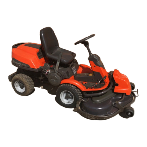
Page 15: Presentation
Presentation Congratulations on your choice of a top quality product which you will enjoy for many years. These instructions describe the Rider 15V2. This rider mower is equipped with a 15 horsepower Kawasaki engine. Location of the controls Ignition lock... -
Page 16: Choke Lever
Throttle control The throttle control regulates the engine speed, and thereby also the rotation speed of the blades. To increase or reduce the engine speed the control is moved forwards or backwards. Avoid idling the engine for long periods, as there is a risk of carbon build-up on the spark plugs. -
Page 17: Cutting Unit
Cutting unit The Rider 15V2 can be fitted with three different cutting units. Side ejector - 970 mm/38" Combi - 1030 mm/41" Combi - 1120 mm/44" See “Maintenance \ Checking the Blades” for identification of the cutting unit. The combi deck functions as a mulching deck when a bio-clip plug is mounted. -
Page 18: Lever For Adjustment Of Cutting Height
Lever for adjustment of cutting height With this lever the cutting height can be adjusted to 9 different positions. Unit with side ejection Combi unit, Seat The seat has a jointed attachment on the front edge and can be tipped forward. The seat can also be adjusted lengthways. -
Page 19: Driving
Before starting • Read the safety instructions and information on the location and function of the controls before starting. • Conduct daily maintenance before starting (see “Maintenance schedule”. Starting the engine 1. Lift up the cutting unit by pulling the lever backwards to locked position (transport posi- tion) and apply the parking brake. - Page 20 5. When the engine starts release the ignition key immediately back to neutral position. IMPORTANT INFORMATION Do not run the starter for more than about 5 seconds at a time. If the engine does not start, wait about 15 seconds before trying again.
-
Page 21: Driving The Machine
Driving the machine 1. Release the parking brake by pressing down the brake pedal. 2. Carefully press down one of the pedals until the correct speed is reached. To drive forwards: press down pedal (1). To reverse: press down pedal (2). 3. -
Page 22: Cutting Tips
4. Push in the lock button on the lift lever and lower down the cutting unit. IMPORTANT INFORMATION The service-life of the drive belts increases considerably if the engine is run at low speed when engaging the blades. For this reason do not increase the throttle until the cutting unit has been lowered to the cutting position. -
Page 23: Stopping The Engine
WARNING! Never drive the machine on ground with a slope of more than 15°. Mow slopes upwards and downwards, never across. Avoid sudden changes in direction. Stopping the engine Preferably allow the engine to idle for a minute to obtain normal working temperature before stopping it if it has been working hard. -
Page 24: Maintenance
The following mainteneance items should be conducted on the machine. For the items not described in these instructions, ask an authorised service workshop. Maintenance Check the engine’s oil level Check the engine’s cooling air inlet Check the fuel pump’s air filter Check the steering wires Check the battery Check the safety system... -
Page 25: Removing The Machine Hoods
Removing the machine hoods Engine hood The engine is accessible for servicing when the engine hood is lifted up. Tilt the seat forward, release the rubber strap under the seat, and tilt the hood backwards. Front hood Release the clip on the front hood and lift off the hood. -
Page 26: Checking And Adjusting Of The Steering Wires
Checking and adjustment of the steering wires The steering is controlled by means of wires. These can in time become slack, which implies that the adjustment of the steering becomes altered. Check and adjust the steering as follows: 1. Dismantle the frame-plate by releasing the screws (two on each side). -
Page 27: Checking And Adjusting The Throttle Wire
Checking and adjustment of the throttle wire Check that the engine responds to the throttle control and that the correct engine speed is achieved at full throttle. If in doubt, contact the service workshop. If adjustment is necessary, adjust the lower wire as follows: 1. -
Page 28: Replacing The Air Filter
Replacing the air filter VARNING! Exhaust system is hot. Allow to cool down. Risk of finger injuries. If the engine seems to lack power or runs irregularly, the reason may be a clogged air filter. It is therefore important to replace the air filter at regular intervals (see ”Maintenance schedule”... -
Page 29: Checking Of The Fuel Pump's Air Filter
Checking of the fuel pump’s air filter Check regularly that the fuel pump’s air filter is free from dirt. The filter can, when necessary, be cleaned with a brush. • Remove the screws and fold out the pump from the bracket. No hoses are to be removed. •... -
Page 30: Inspecting The Safety System
MAINTENANCE Inspecting the safety system The Rider is equipped with a safety system that prevents starting or driving under the following conditions: The engine should only be possible to start when the cutting unit is in its raised position and the hydrostat pedals are in the neutral position. -
Page 31: Main Fuse
Main fuse The fuse is located in a loose holder under the battery case cover, in front of the battery. Type: Flat-blade U-link, 15 A. Do not use any other type of fuse when replacing. A blown fuse indicates that the U-link has burnt off. Pull the fuse out of the holder when replacing. -
Page 32: Fitting The Cutting Unit
Fitting the cutting unit WARNING! Wear protective glasses when fitting the cutting unit. The collet spring which tensions up the belt can go off and cause personal injury. 1. Place the Rider on a flat surface and apply the parking brake. Check that the lever for setting the cutting height is in the lowest position. -
Page 33: Removing The Cutting Unit
6. Move the support wheels to their parking position. 7. Fit the front cover. 8. Secure the collet spring. Removing the cutting unit WARNING! Wear protective glasses when removing the cutting unit. The collet spring which tensions up the belt can go off and cause personal injury. -
Page 34: Checking And Adjusting The Cutting Unit's Ground Pressure
Checking and adjusting the cutting unit’s ground pressure To achieve the best cutting results the cutting unit should follow the underlying surface without pressing too hard against it. The pressure is adjusted with a screw on each side of the machine. 1. -
Page 35: Checking The Cutting Unit's Parallelism
Checking the cutting unit’s parallelism Check the parallelism of the cutting unit as follows: 1. Check the air pressure in the tyres 60 kPa (0.6 kp/cm /8.5 PSI). 2. Place the machine on a level surface. 3. Put the lifting lever in the mowing position. 4. -
Page 36: Replacing The Cutting Unit Belts
Replacing the cutting unit belts Belt change on Combi 103 1. Remove the cutting unit. 2. Remove the front bolt from the parallel strut and tip the strut backwards. Push the height adjustment strut forwards. WARNING! Wear gloves to protect your hands when working with the blades. - Page 37 IMPORTANT INFORMATION The blades on a Combi 103 unit should be set at 90 degrees to each other. In all other cases the blades can collide and cause serious damage to the cutting unit. 5. Fit the protective cover over the belts and replace the parallelism arm.
-
Page 38: Service Position For The Cutting Unit
Service position for the cutting unit The cutting head can be placed in the service position to provide easy access for cleaning, repairs and servicing. In the service position the cutting unit is raised and locked in the vertical position. Placing in service position 1. - Page 39 4. Fit the support wheels on either side of the rear of the cutting unit. WARNING! Wear protective glasses when dismantling the cutting unit. The spring which tensions up the belt can go off and cause personal injury. 5. Disengage the spring for the drive belt tensioning wheel.
- Page 40 WARNING! Observe caution to avoid trapping your hand. 8. Lift off the drive belt (1). Then pull out the pin (2). 9. Pull the frame forwards and refit the pin. 10.Grasp the front edge of the cutting unit, pull out and raise into the service position.
-
Page 41: Checking The Blades
Checking the blades To achieve the best mowing results it is important that the blades are undamaged and well-sharpened. Check that the blades’ attachment screws are tight. IMPORTANT INFORMATION Replacing or sharpening the blades should be conducted by an authorised service workshop. -
Page 42: Replacing The Break-Pin
Replacing the break-pin (Combi 103) The blades are fitted with a break-pin to protect the BioClip unit and its drive when colliding with obstacles. A domed, spring friction washer is fitted to each blade bolt. The washer must always be replaced with a new washer if the blade bolt is loosened. -
Page 43: Lubrication
Checking the engine’s oil level Check the oil level in the engine when the Rider stands horizontal and the engine is switched off. Fold open the engine cover. Release the dip stick and pull out. Wipe off the oil and insert again without screwing it in. The dip stick must be fully screwed down. -
Page 44: Changing The Oil
Changing the oil The oil should be changed for the first time after 8 hours of running time. Thereafter it should be changed every 100 hours of running time. With heavy loads or high temperatures replace the oil after every 50 hours. WARNING! Engine oil can be very hot if it is drained off directly after the... -
Page 45: Checking The Transmission's Oil Level
Checking the transmission’s oil level 1. Remove the transmission cover. Loosen both screws (one on each side) and lift off the transmission cover. 2. Check that there is oil in the transmission’s oil tank. Fill if necessary with engine oil SAE 10W/ 30 (class SF–CC). -
Page 46: Trouble Shooting Schedule
TROUBLE SHOOTING SCHEDULE Problem Engine will not start. Starter does not pull round engine. Engine does not run smoothly. Engine seems to have no power. Engine overheats. Battery does not charge. Machine vibrates. Uneven mowing. – English Procedure • Fuel tank empty. •... -
Page 47: Storage
Winter storage At the end of the season the machine should immediately be put in order for storage, also if it is going to stand idle for more than 30 days. Fuel which is left to stand for long periods (30 days or more) can leave tacky deposits which can block the carburettor and interfere with the engine. -
Page 48: Technical Data
Note that no legal claims are valid on the basis of information in this manual. Use only genuine parts for repairs. The warranty is not valid if non genuine parts are used. – English TECHNICAL DATA Rider 15V2 2020 mm/6.61 ft 880 mm/2.89 ft 1060 mm/3.52 ft 247-260 kg/543-572 lb including unit 855 mm/2.8 ft... -
Page 49: Service Journal
Work done Pre-delivery service 1. Top up battery with acid and recharge for four hours. 2. Fit steering wheel, seat and any optional equipment. 3. Adjust cutting unit: Adjust the lifting springs (the “weight” of the cutting unit should be 12-15 kg/26,5-33 lbs). Only applies to Combi deck. Adjust cutting unit so that rear edge is about 2–4 mm/1/8"... - Page 50 SERVICE JOURNAL Date, mileage, stamp, sign Work done – English...
- Page 51 SERVICE JOURNAL Date, mileage, stamp, sign Work done English –...
- Page 52 SERVICE JOURNAL Date, mileage, stamp, sign Work done – English...
- Page 53 SERVICE JOURNAL Date, mileage, stamp, sign Work done ´®z+H-•¶5O¨...
- Page 54 – English...
- Page 55 114 01 39-95 ´®z+H-•¶5O¨ 2002W45...