
Related Manuals for LG LCB5100-BN


Summary of Contents for LG LCB5100-BN
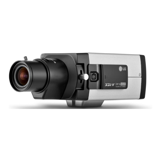
- Page 1 OWNER'S MANUAL Color Video Camera Please read this manual carefully before operating your set and retain it for future reference. MODEL LCB5100-BN LCB5100-BP LCB5100 Series...
- Page 2 FCC WARNING: This equipment may generate or use CAUTION radio frequency energy. Changes or modifications to this equipment may cause harmful interference unless the modifications are expressly approved in the instruction RISK OF ELECTRIC SHOCK manual. The user could lose the authority to operate this DO NOT OPEN equipment if an unauthorized change or modification is made.
- Page 3 Warning: The product has been dropped or the case is • Caution: Danger of explosion if battery is incorrectly replaced. Replaced only with the same or equivalent broken, turn off the power and unplug the power cord. type recommended by the manufacturer. Dispose (This may cause fire, electric shock, or injury.) of used batteries according to the manufacturer’s Warning: If the product has no video out or sound, please...
- Page 4 LG Electronics hereby declares that this/ Disposal of your old appliance these product(s) is/are in compliance with the essential requirements and other When this crossed-out wheeled bin relevant provisions of Directive 2004/108/ symbol is attached to a product it EC, 2006/95/EC, and 2009/125/EC.
-
Page 5: Important Safety Instructions
Important Safety Instructions Read these instructions. and the point where they exit from the apparatus. Keep these instructions. 11. Only use attachments/accessories specified by the manufacturer. Heed all warnings. 12. Use only with the cart, stand, tripod, bracket, or Follow all instructions. table specified by the manufacturer, or sold with the Do not use this apparatus near water. -
Page 6: Cautions For Safe Operation
Cautions for Safe Operation Power Supply Operating and storage location This camera must always be operated by DC 12 V or AC 24 Avoid viewing a very bright object (such as light fittings) V Certified/Listed, class 2 power supply only. during an extended period. -
Page 7: Table Of Contents
Contents Features ................8 3D-DNR Setting ...............27 Part Names and Functions ............ 9 Privacy Mask Setting .............27 Connections ..............11 Special Menu Settings ............29 Precautions ................11 SYSTEM Setting ...............33 Specification ..............34 Connection Overview ............11 Connecting Display device ..........12 Connecting Power Source ...........12 Mounting the Lens ..............13 Flange-back Adjustment ..........15 Mounting the camera ............16... -
Page 8: Features
Features This Color Video Camera is designed for installation in a video surveillance system. This manual contains instructions on how to install and manage the Color Video Camera in your video surveillance system. Should you require any technical assistance, please contact authorized service center. •... -
Page 9: Part Names And Functions
Part Names and Functions a Lens mount cap b c d The lens mount of the camera is covered using a cap to protect it. Remove the lens cap covering the lens. b Camera installation bracket The bracket can be fixed at the top or bottom of the camera. - Page 10 Part Names and Functions f Power input terminal Supplies AC 24 V or DC 12 V from an external power source. g Power indicator Lights when the camera is powered. h Video output connector (BNC type) Supplies analog video signal (composite) to the connected device such as a DVR or monitor.
-
Page 11: Connections
Connections Precautions • Be sure to switch off the unit before installation and connection. • A qualified service person, complying with all applicable codes, should perform all required hardware installation. • Do not expose the power and connection cable to moisture, which may cause damage to the unit. Connection Overview... -
Page 12: Connecting Display Device
Connections Connecting Display device Connecting Power Source The video signal connection between the camera and the Connect power, using the method listed below: monitor. Remove the insulation on the power cable as illustrated. (a) Attach the terminal tips. (b) Connect to the DC 12 V / AC 24 V UL Listed, Class 2 Power Supply only on the unit. -
Page 13: Mounting The Lens
Connections Mounting the Lens Remove the lens mount cap from the camera. Connect the lens plug to the lens iris output Install the auto-iris lens. connector (LENS) on the side of the camera. 2-1. CS mount type lens When using lenses from other makers, the plug shape Carefully align the lens mount with the camera may not correspond to the terminal on the camera. - Page 14 Connections Lens iris output connector Rewire the lens iris plug Pin layout for the lens iris output connector. Cut off the plug of the lens cable, cut off approximately 8 mm of the insulation, and then strip approximately 2 mm of the ends of the cable sheaths.
-
Page 15: Flange-Back Adjustment
Connections Flange-back Adjustment The adjustment is required only when a lens without focus-adjusting mechanism is mounted, or when a lens with adjusting mechanism is mounted and focus that is more accurate is needed. Loosen the flange-back fixing lever. Up and down the flange-back adjusting lever to obtain a focused point while watching the monitor screen. -
Page 16: Mounting The Camera
Connections Mounting the camera The mounting bracket can be secured on either the top or bottom of the camera. Use the same set of screws to attach the mounting bracket on the camera. Note: If using a camera mounting bracket, select a location that is strong enough to bear the full weight of the camera and the mounting bracket for long periods, and install the camera and mounting bracket securely. -
Page 17: Menu Operation
Menu Operation OSD Menu control buttons BUTTON Description This camera utilizes an on-screen user MENU. To set items Used to move upper direction on the on the menu, use the following buttons. menu screen. Use this button to select an item or adjust the parameters. UP button Used to move lower direction on the menu screen. -
Page 18: Osd Menu Overview
Menu Operation OSD Menu Overview BURST ON/OFF LEVEL LOW/ MIDDLE/ HIGH/USER AUTO The following table shows the list of menu items and op- DWELL 3 SEC to 60 SEC DAY/ TIME tions. You can adapt the camera to your requirements by NIGHT setting up the respective items in these menus. - Page 19 Menu Operation MASK 1 to 2 SELECTION MASK 1 to 8 OFF,MOZAIC, SELECTION DISPLAY COLOR1 to OFF,MOZAIC, COLOR 8 DISPLAY COLOR1 to POLYGON PRIVACY SHAPE COLOR 8 MASK POSITION ,/ 2 to 98 POSITION RECTANGLE POSITION ;. 2 to 98 TOP/RET/ EXIT SIZE ,/...
-
Page 20: General Operation
Menu Operation General Operation previous setup menu. • RET: Return to the previous. Press [SET] button. • TOP: Return to the CAMERA SETTING menu [CAMERA SETTING] menu appears on the monitor. screen. • END: Exit the setup menu. Exposure Settings You can set the exposure options using the EXPOSURE menu. -
Page 21: Backlight Setting
Menu Operation Backlight setting > AREA SETTING: Use [LEFT] or [RIGHT] button to select a area then use [UP] or [DOWN] Use Backlight option to view the object clearly in backlight button to select a [ON] or [OFF]. Press [SET] conditions. - Page 22 Menu Operation BRIGHTNESS setting AGC (Automatic Gain Control) setting You can increase the brightness of the darkened video. If the images are too dark, change the maximum [AGC] If you set the brightness to lower value, the image is value to make the images brighter. But noise is increase. darkened.
- Page 23 Menu Operation SHUTTER (Shutter Speed) setting Note: When the SHUTTER is set to AUTO, the picture may become Select the desired shutter speed for camera exposure. You unstable if the camera faces a bright fluorescent light can change the shutter speed to higher speed to capture directly.
-
Page 24: White Balance Settings
Menu Operation > SENS-UP LIMIT: Use [LEFT] or [RIGHT] button Select [WHITE BAL] option. to set the SENS-UP limit. Use [LEFT] or [RIGHT] button to select a mode then • OFF: Not used. press [SET]. Note: • ATW (Auto-Tracing White Balance): Use [LEFT] or [RIGHT] button to select the ATW. -
Page 25: Day & Night Setting
Menu Operation Day & Night Setting select [ON] or [OFF]. > LEVEL: Use [LEFT] or [RIGHT] button to select a level. > DWELL TIME: Use [LEFT] or [RIGHT] button to select a dwell time. • DAY: Color mode enabled. • NIGHT: Black-and-white mode enabled. -
Page 26: Motion Detection Setting
Menu Operation Motion Detection Setting • Use [UP] or [DOWN] to select an option then use [LEFT] or [RIGHT] button to adjust the option. The motion detection detects the moving objects in the > POSITION : Moves horizontal position of scene by monitoring changes in brightness level. -
Page 27: 3D-Dnr Setting
Menu Operation 3D-DNR Setting Privacy Mask Setting This function is aiming at the protection of personal privacy, selecting a screen part black not to be displayed in the screen. Up to 14 zones can be registered. Select [3D-DNR] option. If pictures are not clear due to brightness, this option would reduce the noise of picture. - Page 28 Menu Operation > Use [UP] or [DOWN] to select an option then of the mask. use [LEFT] or [RIGHT] button to adjust the SIZE : Enlarge or decrease the option. horizontal size of the mask. POSITION : Moves horizontal SIZE : Enlarge or decrease the position of the mask.
-
Page 29: Special Menu Settings
Menu Operation D-ZOOM (Digital Zoom ) Setting adjustments are applied in common from COLOR 1 to COLOR 7, after mask setting. You can select the digital zoom level. Special Menu Settings This menu lets you adjust and set up D-ZOOM, D-EFFECT, SHARPNESS, COLOR, SYNC, USER TITLE, LANGUAGE function by yourself in the [SPECIAL] menu. - Page 30 Menu Operation • TILT: Use [LEFT] or [RIGHT] button to move the • V-FLIP: Flip the picture vertically. screen. • OFF: Turn off the digital effect. Note: SHARPNESS Setting If you set the [D-ZOOM] to [ON], the ZOOM level is set to The degree to which the boundary of the two portions is [x1.0] automatically.
- Page 31 Menu Operation COLOR Setting SYNC Setting You can switch the displayed picture to gray scale or color. Select [SYNC] option on the [SPECIAL] menu. Select [COLOR] option on the [SPECIAL] menu. The [SYNC] option is set to [INT] automatically. Use [LEFT] or [RIGHT] button to change a adjust the Note: option.
-
Page 32: Language Setting
Menu Operation USER TITLE Setting • : Moves cursor to left or right. You can use the camera identification to assign a number and character to the camera. To disappear the user title, LANGUAGE Setting select [OFF]. Select the viewer language for the camera setup menu and Select [USER TITLE] option on the [SPECIAL] menu. -
Page 33: System Setting
Menu Operation SYSTEM Setting Select the [SYSTEM] menu. Press [SET] button and the [SYSTEM] menu appears. Use [UP] or [DOWN] button to select the option. • FACTORY RESET: To reset the camera setting to factory setting, select the [FACTORY RESET] option. -
Page 34: Specification
Specification Item LCB5100-BN LCB5100-BP Signal System NTSC Total Pixels number 520 000 Pixels 610 000 Pixels Effective Pixels number 480 000 Pixels 570 000 Pixels Image Sensor 6 mm (1/3 Type) Exview HAD II CCD XDI-V Lens C/CS Mount Horizontal Resolution... - Page 35 Specification Item LCB5100-BN LCB5100-BP Video Output 1 Vp-p Composite (75 Ω) Electronic Shutter 1/60 to 1/120 000 1/50 to 1/120 000 Backlight Compensation BLC / HSBLC / OFF Motion Detection 8 Zones Privacy Masking 14 Mask Zones 2D + 3D-DNR...