Table of Contents
Advertisement
CAUTION, MICROWAVE RADIATION .............................................................................................................. 1
WARNING ........................................................................................................................................................... 1
PRODUCT SPECIFICATIONS .......................................................................................................................... 2
GENERAL INFORMATION ................................................................................................................................. 2
APPEARANCE VIEW ........................................................................................................................................ 3
OPERATION SEQUENCE ................................................................................................................................. 4
FUNCTION OF IMPORTANT COMPONENTS ................................................................................................. 7
SERVICING ..................................................................................................................................................... 10
TEST PROCEDURE ......................................................................................................................................... 12
TOUCH CONTROL PANEL ASSEMBLY ......................................................................................................... 20
COMPONENT REPLACEMENT AND ADJUSTMENT PROCEDURE ............................................................ 26
MICROWAVE MEASUREMENT ..................................................................................................................... 31
WIRING DIAGRAM .......................................................................................................................................... 32
PICTORIAL DIAGRAM .................................................................................................................................... 34
CONTROL PANEL CIRCUIT ............................................................................................................................ 35
PRINTED WIRING BOARD .............................................................................................................................. 36
PARTS LIST .................................................................................................................................................... 37
MIX CONV
DEFROST
SENSOR
COOK LBS
OZ
KG
HELP
INFO DISPLA Y
HELP
MULTI
REHEAT
COOK
SENSOR
FRESH
REHEAT
JACKET
VEGETABL ES
PIE
POTATO
FFOZEN
VEGETABL ES
CASSEROL ES
DESSERTS
MODEL
LESS
MORE
LOW MIX
HIGH MIX GRILL
CONVE C
POWER
EASY
LEVEL
DEFROS T
MEMOR Y PREHEA
T
1
2
3
4
5
40˚C
70˚C
130˚C
150˚C
160˚C
6
7
8
9 O
180˚C
200˚C
220˚C
230˚C
250˚C
STOP
CLOC K
INSTANT COOK
CLEAR
START
In interests of user-safety the oven should be restored to its original
condition and only parts identical to those specified should be used.
TABLE OF CONTENTS
SHARP CORPORATION
43
CONVECTION
MICROWAVE OVEN
R-980E
R-980E
S5102R980EPJ/
Page
Advertisement
Table of Contents

Related Manuals for Sharp R-980E


Summary of Contents for Sharp R-980E
-
Page 1: Table Of Contents
R-980E SERVICE MANUAL S5102R980EPJ/ CONVECTION MICROWAVE OVEN MIX CONV DEFROST SENSOR COOK LBS HELP INFO DISPLA Y HELP MULTI REHEAT COOK SENSOR FRESH REHEAT JACKET VEGETABL ES POTATO FFOZEN R-980E VEGETABL ES CASSEROL ES DESSERTS MODEL LESS MORE LOW MIX... - Page 2 R-980E...
-
Page 3: Caution Microwave Radiation
MICROWAVE OVEN R-980E APPEARANCE VIEW GENERAL IMPORTANT INFORMATION This Manual has been prepared to provide Sharp Corp. Service engineers with Operation and Service Information. OPERATING SEQUENCE It is recommended that service engineers carefully study the entire text of this manual, so they will be qualified to render satisfactory customer service. -
Page 4: Product Specifications
R-980E PRODUCT SPECIFICATIONS ITEM DESCRIPTION Power Requirements 230 - 240 Volts 50 Hertz Single phase, 3 wire earthed Power Consumption 1600 W (Microwave) 1600 W (Convection) Power Output 900 watts (IEC Test Procedure) Operating frequency of 2450MHz Convection heater 1500 W... -
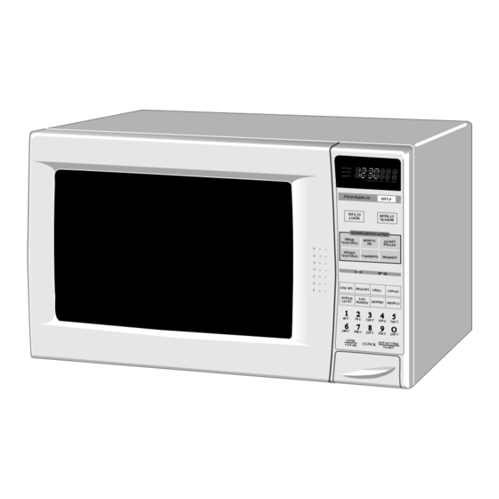
Page 5: Appearance View
R-980E APPEARANCE VIEW 1. Ventilation opening 2. Oven lamp 3. Door hinges 4. Door safety latches 5. See through door 6. Door seal and sealing surfaces 7. Door open button 8. Touch control panel 9. Digital readout 10. Wave guide cover 11. -
Page 6: Operation Sequence
(Figure O-1): 2) When the door is closed, from the open position, the 1. The display flashes “SHARP”, "MICRO-", "WAVE", monitor switch contacts first open, and then the contacts 'OVEN". - Page 7 R-980E unit de-energizing the relay (RY4) and opening the 4. The heater relay (RY3) is energized, adding the mains circuit to the damper motor. supply voltage to the convection heater. 3. The coil of heater relay (RY3) is energized by the CPU 5.
- Page 8 R-980E EASY DEFROST COOKING The EASY DEFROST key is a special function key to defrost meats and poultry faster and better. EASY DEFROST key has 4 defrost stages. EASY DEFROST automatically defrosts roast beef, etc. When EASY DEFROST is selected and the food weight is entered by using the number pads, the oven will cook according to the special cooking sequence.
-
Page 9: Function Of Important Components
R-980E FUNCTION OF IMPORTANT COMPONENTS DOOR OPEN MECHANISM THERMAL CUT-OUT 150˚C (CONV.) The door is opened by pushing the open button on the The oven thermal cut-out located on the left side of the control panel, refer to the Figure D-1. - Page 10 R-980E beyond the rated peak reverse voltage 1.7 KV in the temperature inside the oven cavity reaches the selected voltagedoubler circuit. temperature, the convection heater is de-energized. When 3. D2 of the rectifier is shorted. the temperature inside the oven cavity drops below the 4.
- Page 11 R-980E (RY4) is energized, and the damper is returned to the open position. NOTE: If the damper door is not in the proper position, closed during convection or open during microwave, the control unit will stop oven operation after 1 minute.
-
Page 12: Servicing
If the water remains cold carry out 3D checks and re- examine the connections to the component being tested. Sharp recommend that wherever possible fault-finding is carried out with the supply disconnected. It may, in some cases, be necessary to connect the supply after... - Page 13 R-980E CK = Check / RE = Replace TEST PROCEDURE A B C D E E E F G G H I J J J J K M N O O O O O O P Q RE CKCK CK RE...
-
Page 14: Test Procedure
R-980E TEST PROCEDURES PROCEDURE COMPONENT TEST LETTER MAGNETRON TEST NEVER TOUCH ANY PART IN THE CIRCUIT WITH YOUR HAND OR AN INSULATED TOOL WHILE THE OVEN IS IN OPERATION. CARRY OUT 3D CHECK. Isolate the magnetron from high voltage circuit by removing all leads connected to filament terminal. - Page 15 R-980E TEST PROCEDURES PROCEDURE COMPONENT TEST LETTER Initial temperature ..................... T1 = 11 C Temperature after (47 + 2) = 49 sec..............T2 = 21 C Temperature difference Cold-Warm .............. T1 = 10 C Measured output power The equation is “P = 90 x T” ..........P = 90 x 10 C = 900 Watts JUDGMENT: The measured output power should be at least 15 % of the rated output power.
- Page 16 R-980E TEST PROCEDURES PROCEDURE COMPONENT TEST LETTER rectifier, high voltage wire or filament winding of the power transformer is shorted. CARRY OUT 4R CHECKS. NOTE: FOR MEASUREMENT OF THE RESISTANCE OF THE RECTIFIER, THE BATTERIES OF THE MEASURING INSTRUMENT MUST HAVE A VOLTAGE AT LEAST 6 VOLTS, BECAUSE OTHERWISE AN INFINITE RESISTANCE MIGHT BE SHOWN IN BOTH DIRECTIONS.
- Page 17 R-980E TEST PROCEDURES PROCEDURE COMPONENT TEST LETTER Table: Temperature Fuse and Thermal cut-out Test Temperature of “ON” condition Temperature of “OFF” condition Indication ofohmmeter Parts Name (closed circuit) (˚C) (open circuit) (˚C) (When room temperature is approx. 20˚C) Temp. fuse 150˚C This is not resetable type.
- Page 18 R-980E TEST PROCEDURES PROCEDURE COMPONENT TEST LETTER If incorrect readings are obtained, replace the motor. CARRY OUT 4R CHECKS. MONITOR RESISTOR TEST CARRY OUT 3D CHECKS. Disconnect the leads from the monitor resist. Using an ohmmeter and set on a low range. Check between the terminals of the monitor resistor.
- Page 19 R-980E TEST PROCEDURES PROCEDURE COMPONENT TEST LETTER 2-3 Other possible troubles caused by defective control unit. a) Buzzer does not sound or continues to sound. b) Clock does not operate properly. c) Cooking is not possible. d) Proper temperature measurement is not obtained.
- Page 20 R-980E TEST PROCEDURES PROCEDURE COMPONENT TEST LETTER STEPS OCCURRENCE CAUSE OR CORRECTION The rated voltage is not applied between Pin No. 9 of the 5-pin connector (A) and the Check supply voltage and oven power cord. common terminal of the relay RY1.
- Page 21 R-980E TEST PROCEDURES PROCEDURE COMPONENT TEST LETTER TESTING METHOD FOR AH SENSOR AND/OR CONTROL UNIT To determine if the sensor is defective, the simplest method is to replace it with a new replacement sensor. (1) Disconnect oven from power supply and remove outer case.
-
Page 22: Touch Control Panel Assembly
R-980E TOUCH CONTROL PANEL ASSEMBLY OUTLINE OF TOUCH CONTROL PANEL The touch control section consists of the following units 4) ACL Circuit as shown in the touch control panel circuit. A circuit to generate a signals which resetting the LSI to the initial state when power is applied. - Page 23 R-980E DESCRIPTION OF LSI LSI(IZA840DR): The I/O signals of the LSI(IZA840DR) are detailed in the following table. Pin No. Signal Description Connected to GND. Anode (segment) of Fluorescent Display light-up voltage: -30V. Vp voltage of power source circuit input. AVSS Power source voltage: -5V.
- Page 24 R-980E Pin No. Signal Description Magnetron high-voltage circuit driving signal. To turn on and off the cook relay(RY2). In HIGH operation, the VARI MODE ON TIME OFF TIME signals holds "L" level during micro- HIGH (100% power) 32 sec. 0 sec.
- Page 25 R-980E Pin No. Signal Description Signal similar to P27. When any one of G-3 line key on key matrix is touched, a corresponding signal will be input into P25. Signal similar to P27. When any one of G-4 line key on key matrix is touched, a corresponding signal will be input into P24.
- Page 26 R-980E Pin No. Signal Description 54-56 P02-P00 Digit selection signal. Signal similar to P55. 57-59 P37-P35 Digit selection signal. Signal similar to P55. 60-64 P34-P30 Used for initial balancing of the bridge circuit (absolute humidity sensor). ABSOLUTE HUMIDITY SENSOR CIRCUIT...
- Page 27 R-980E SERVICING 1. Precautions for Handling Electronic Components For those models, check and repair all the controls This unit uses CMOS LSI in the integral part of the (sensor-related ones included) of the touch control circuits. When handling these parts, the following panel while keeping it connected to the oven.
-
Page 28: Component Replacement And Adjustment Procedure
4. If the outer case (cabinet) is not fitted. Please refer to ‘OVEN PARTS, CABINET PARTS, DOOR PARTS’, when carrying out any of the following removal procedures: WARNING FOR WIRING 3) Sharp edge: To prevent an electric shock, take the following Bottom plate, Oven cavity, Weveguide flange, manners. - Page 29 R-980E 6. Re-install the outer case and check that the oven is NOTE: LIVE(ORANGE) WIRE MUST BE CONNECTED operating properly. TO THE CABINET-SIDE OF THE POWER TRANSFORMER. MAGNETRON REMOVAL 1. CARRY OUT 3D CHECKS When removing the screws hold the magnetron and 2.
- Page 30 R-980E NOTE: 1. Before attaching a new key unit, remove remaining 2. Remove the two (2) screws holding the panel frame to adhesive on the control panel frame surfaces the back plate. completely with a soft cloth soaked in alcohol.
-
Page 31: Cord Holder Removal
R-980E Coil Shaft Groove joint pliers Center of Table Shaft bracket Stator These are the position where should be Axis pinched with pliers Stator Bracket Rotor Rotor Rear view Side view CORD HOLDER REMOVAL 1. Remove the one (1) special screw holding the cord holder to the rear cabinet, using the special driver LHSTIX DLR4-100T. -
Page 32: Door Disassembly
R-980E After the adjustment, make sure of the following: LATCH HOOK 1. The in and out play of the door remains less than 0.5 UPPER LATCH SWITCH mm at latched position. STOP SWITCH 2. The stop switch and lower latch switch interrupt the circuit before the door can be opened. -
Page 33: Microwave Measurement
R-980E MICROWAVE MEASUREMENT Recommended instruments are: After adjustment of door latch switches, monitor switch NARDA 8100 and door are completed individually or collectively, the NARDA 8200 following leakage test must be performed with a survey HOLADAY HI 1500 instrument and it must be confirmed that the result meets... -
Page 34: Wiring Diagram
R-980E SCHEMATIC NOTE: CONDITION OF OVEN 1. DOOR CLOSED. NOTE: indicates components with potential above 250V. 2. CLOCK APPERARS ON DISPLAY TEMPERATURE THERMAL CUT-OUT 95˚C (FAN) FUSE 150˚C NOISE FILTER (MAGNETRON) COM. (RY1) N.O. (RY1) POWER TRANSFORMER COM. (RY3) COM. - Page 35 R-980E SCHEMATIC NOTE: CONDITION OF OVEN 1. DOOR CLOSED. 2. MIX COOKING PAD TOUCHED. 3. COOKING TIME PROGRAMMED. 4. START PAD TOUCHED. 5. RY2 AND RY3 WILL ALTERNATELY CLOSED NOTE: indicates components with potential above 250V. DURING COOK CYCLE. THERMAL CUT-OUT TEMPERATURE 95˚C (FAN)
-
Page 36: Pictorial Diagram
R-980E HV. RECTIFIER... -
Page 37: Control Panel Circuit
R-980E 3.3k 3.3k 3.3k 3.3k 3.3k 3.3k 3.3k 100k 100k 100k 3.3k R100 3.3k 3.3k 3.3k 3.3k IZA840DR 4.7k 2.2kF (J7) 4.7k (J5) HZ4A2 100F (J3) /35v (J6) /50v 6.8k (J4) /50v 0.01 HZ5C2 (J2) /25v 3.3k /35v /50v /50v... -
Page 38: Printed Wiring Board
R-980E (C81) R86(J8) (C80) (R45) (C45) (CN - D) (R47) (R48) (R49) (C46) (C47) (J7) (J5) (J3) (J2) (J4) (J6) CONV HEATER COM Figure S-3. Printed Wiring Board... -
Page 39: Parts List
R-980E PARTS LIST Note: The parts marked " " may cause undue microwave exposure. The parts marked "*" are used in voltage more than 250V. REF. NO. PART NO. DESCRIPTION Q'TY CODE ELECTRICAL PARTS 1- 1 FH-DZA058WRK0 High voltage rectifier assembly... - Page 40 R-980E Note: The parts marked " " may cause undue microwave exposure. The parts marked "*" are used in voltage more than 250V. REF. NO. PART NO. DESCRIPTION Q'TY CODE VSKRA101M//-3 Transistor (KRA101M) VSDTA123ES/-3 Transistor (DTA123E) Q20-23 VSKRA101M//-3 Transistor (KRA101M)
- Page 41 R-980E Note: The parts marked " " may cause undue microwave exposure. The parts marked "*" are used in voltage more than 250V. REF. NO. PART NO. DESCRIPTION Q'TY CODE 4-33 PDUC-A270WRF0 Cooling fan duct 4-34 LANGFA089WRW0 Chassis support 4-35...
- Page 42 R-980E...
- Page 43 R-980E CONTROL PANEL PARTS 3-1E 3-1F 7-18 3-2-1 7-18 DOOR PARTS 3-2-3 3-2-2 5-11 5-10 5-10 MISCELLANEOUS Actual wire harness may be different than illustration.
-
Page 44: Packing And Accessories
R-980E PACKING AND ACCESSORIES TRAY HOLDER (SPADFA348WRE0) TOP PAD ASSEMBLY FPADBA362WRK0 DOOR PROTECTION SHEET SPADPA178WRE0 4-3 TURNTABLE TRAY PLASTIC BAG SSAKHA012WRE0 6-7 OPERATION MANUAL 6-3 COOK BOOK MICROWAVE OVEN 4-2 TURNTABLE SUPPORT BOTTOM PAD ASSEMBLY FPADBA363WRK0 TRAY PACKING FOAM PACKING CASE...