Table of Contents
Advertisement
Quick Links
Advertisement
Table of Contents

Related Manuals for Bosch PRS-1AIP1


Summary of Contents for Bosch PRS-1AIP1
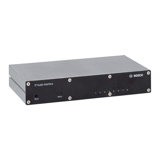
- Page 1 IP Audio Interface PRS-1AIP1 Operating Manual...
-
Page 3: Table Of Contents
Important Safety Instructions Short information Purpose Digital document Intended audience Related documentation Alerts and notice signs Conversion tables Disclaimers 2.7.1 Bosch Security Systems B.V. System overview Application Key product features Package content Product view 3.4.1 Front view 3.4.2 Rear view... - Page 4 Control Inputs (1..8) 7.1.2 Control Outputs (1..8) 7.1.3 Audio 7.1.4 Codec 7.1.5 Power, Fault & Temperature 7.1.6 Last Caller 7.1.7 Restart Page Maintenance Technical data Electrical Mechanical Environmental conditions EMC and Safety 2013.03 | V2.0 | Operating Manual Bosch Security Systems B.V.
-
Page 5: Important Safety Instructions
– Do not block any ventilation openings. – Always install the apparatus according to Bosch installation instructions. – Do not install the apparatus near any heat sources, for example: radiators, heat registers, stoves or other apparatus (including amplifiers) that generate heat. -
Page 6: Short Information
In this manual a ‘notice’ is used to provide tips, or to give some extra information: Notice! Alert containing additional information. Usually, not observing a ‘notice’ does not result in damage to the equipment or personal injuries. 2013.03 | V2.0 | Operating Manual Bosch Security Systems B.V. -
Page 7: Conversion Tables
Bosch Security Systems B.V. disclaim all warranties with regard to the information provided in these instructions. In no event shall Bosch Security Systems B.V. be liable for any special, indirect or consequential damages whatsoever resulting from loss of use, data or profits, whether in action of contract, negligence or other tortuous action, arising out of or in connection with the use of the information provided in these Installation and User Instructions. -
Page 8: System Overview
CD with software and Installation and User Instructions – Power supply for universal input voltage – Screw block terminals (4 x 8 pin, 6 x 3 pin) – Label stickers for screw block terminals 2013.03 | V2.0 | Operating Manual Bosch Security Systems B.V. -
Page 9: Product View
One or more ON: one or more inputs activated – One or more slow flashing: open input circuit(s), while supervision is enabled – One or more fast flashing: shorted input circuit(s), while supervision is enabled Bosch Security Systems B.V. Operating Manual 2013.03 | V2.0 |... -
Page 10: Rear View
Default (no fault): open contacts (voltage free relay contact). – 7-8: Fault contact Audio Output 2 Balanced, line level with pilot tone generation. – 1: - – 2: ground – 3: + 2013.03 | V2.0 | Operating Manual Bosch Security Systems B.V. - Page 11 Back-up power supply input With battery under-voltage detection. – 1: + – 2, 3: ground Mains power supply input With mains power failure detection. – Centre: + – Ring: ground Bosch Security Systems B.V. Operating Manual 2013.03 | V2.0 |...
-
Page 12: Installation
The eight green Control I/O LEDs (3) and red status LED (2) go OFF and the green status LED (2) switches ON. The IP Audio Interface is now ready for configuration, but it is recommended to set a static IP address, Connect to web browser, page 16. 2013.03 | V2.0 | Operating Manual Bosch Security Systems B.V. -
Page 13: No Dhcp Server Is Found
Do not connect a voltage or current source to the Control Input contacts. Control Outputs Connect the Control Outputs 1..8 (4 and 5) that are needed as described in Product view, page Bosch Security Systems B.V. Operating Manual 2013.03 | V2.0 |... -
Page 14: Connection Options
IP address: 192.168.100.255 configured in the transmitter as Partner address. Then all partners with addresses starting with 192.168.100 receive this stream. Typically, routers in a WAN do not support Broadcast mode. Figure 5.3: Broadcast example (1=LAN/WAN) 2013.03 | V2.0 | Operating Manual Bosch Security Systems B.V. -
Page 15: Multicast
Re-broadcast means: a local device receives a data stream from a remote device and resends it to other devices (Partners) in a LAN or WAN. Figure 5.5: Re-broadcasting (1=Internet, 2=Router, 3=LAN/WAN) Bosch Security Systems B.V. Operating Manual 2013.03 | V2.0 |... -
Page 16: Configuration
The status screen is updated dynamically. The current implementation of this feature does not support all web browsers, for example, Google Chrome. Figure 6.1: Status screen example 2013.03 | V2.0 | Operating Manual Bosch Security Systems B.V. -
Page 17: Configuration Page
Outgoing Route Table – Control Audio Settings Supervision Control I/O mapping – Control Input Mapping Table – Control Output Mapping Table Serial SNMP Security Default Settings Figure 6.2: Configuration (Network) screen example Bosch Security Systems B.V. Operating Manual 2013.03 | V2.0 |... -
Page 18: Network
IP address. This way start up is faster. Submit / Cancel button Submit saves the set values, restarts the device and returns back to the last screen. Cancel restores the last submitted values. 2013.03 | V2.0 | Operating Manual Bosch Security Systems B.V. -
Page 19: Streaming
The Back channel period determines the rate at which control data is sent back to the audio transmitter within the range 100 ms to 4 s. The audio transmitter will then update the control output at a rate between 300 ms and 12 s. Bosch Security Systems B.V. Operating Manual 2013.03 | V2.0 |... -
Page 20: Partner Table
(highest number) is accepted. Existing streams with a lower priority are overridden, even if selected by a Control Input. Full duplex connections are considered to be permanent one-to-one connections for which Priority settings are ignored. 2013.03 | V2.0 | Operating Manual Bosch Security Systems B.V. - Page 21 You can enter the port number of the partner device here, between 0 and 65535. Submit / Cancel button Submit saves the set values, restarts the device and returns back to the last screen. Cancel restores the last submitted values. Bosch Security Systems B.V. Operating Manual 2013.03 | V2.0 |...
-
Page 22: Outgoing Route Table
20 kHz Pilot Tone on Audio Input 2. Submit / Cancel button Submit saves the set values, restarts the device and returns back to the last screen. Cancel restores the last submitted values. 2013.03 | V2.0 | Operating Manual Bosch Security Systems B.V. -
Page 23: Control
80 is used. Submit / Cancel button Submit saves the set values, restarts the device and returns back to the last screen. Cancel restores the last submitted values. Bosch Security Systems B.V. Operating Manual 2013.03 | V2.0 |... -
Page 24: Audio Settings
STATUS page, see Status page, page 39. Microphone gain Default: 0 dBYou can adjust the gain of the microphone input (0...22.5 dB) to adapt it to the microphone that is used. 2013.03 | V2.0 | Operating Manual Bosch Security Systems B.V. - Page 25 Higher delay values can be used with the purpose of acoustically aligning loudspeakers connected to different IP Audio Interfaces, e.g. in tunnel applications. Bosch Security Systems B.V. Operating Manual 2013.03 | V2.0 |...
- Page 26 This is Half Duplex (or Simplex) mode. Submit / Cancel button Submit saves the set values, restarts the device and returns back to the last screen. Cancel restores the last submitted values. 2013.03 | V2.0 | Operating Manual Bosch Security Systems B.V.
-
Page 27: Supervision
Enter a value in the range 0 – 255 seconds. This is the time between consecutive pings to supervised partners (checked as such in the Partner Table, see Partner Table, page 20). Bosch Security Systems B.V. Operating Manual 2013.03 | V2.0 |... - Page 28 Submit / Cancel button Submit saves the set values, restarts the device and returns back to the last screen. Cancel restores the last submitted values. 2013.03 | V2.0 | Operating Manual Bosch Security Systems B.V.
-
Page 29: Control Input Mapping Table
Output is de-activated as soon as one of Control Inputs is deactivated. Submit / Cancel button Submit saves the set values, restarts the device and returns back to the last screen. Cancel restores the last submitted values. Bosch Security Systems B.V. Operating Manual 2013.03 | V2.0 |... -
Page 30: Control Output Mapping Table
The Fault Relay contact will be Closed. Submit / Cancel button Submit saves the set values, restarts the device and returns back to the last screen. Cancel restores the last submitted values. 2013.03 | V2.0 | Operating Manual Bosch Security Systems B.V. -
Page 31: Serial (Rs-232/Rs-485)
Submit / Cancel button Submit saves the set values, restarts the device and returns back to the last screen. Cancel restores the last submitted values. Bosch Security Systems B.V. Operating Manual 2013.03 | V2.0 |... -
Page 32: Snmp
The Bosch specific branch (where the Bosch specific traps are assigned sequentially): iso(1).org(3).dod(6).internet(1).private(4).enterprises(1).barix(17491).oem(10). bosch(2) The Bosch branch is further subdivided to define the supervised faults as data objects: prs1aip1(1).faults(1) One trap is defined which shall deliver a 16 bit fault register value as an INTEGER and a fault reason as an enumerated INTEGER. -
Page 33: Security
To log out click on the Logout button below the menu bar. On the Reboot page only one user can log in at a time. Other login attempts will be refused. Bosch Security Systems B.V. Operating Manual 2013.03 | V2.0 |... -
Page 34: Default Settings
Hard default settings To revert all settings (including the Network configuration) to factory defaults, the Reset button (1) has to be pressed for about 5..10 seconds while the device is powered. 2013.03 | V2.0 | Operating Manual Bosch Security Systems B.V. -
Page 35: Configuration View
I/O Status – Network Configuration – Streaming Configuration – Control Configuration – Audio Configuration – Supervision – Serial Configuration – SNMP Configuration – Security Configuration Figure 6.15: Configuration View example screen Bosch Security Systems B.V. Operating Manual 2013.03 | V2.0 |... -
Page 36: Update
Unpack the zip file that contains the update kit and save it to a local drive. The update kit can be found on the supplied CD and/or Bosch Security Systems restricted download web page. Click UPDATE on top of the page. The update page appears which shows the current device HW/SW version and a link. - Page 37 IP Audio Interface Configuration | en Click Browse and select the file named compound.bin inside the folder update_rescue. See “Compound.bin selection” screen. Open this file. Figure 6.18: Compound.bin selection Bosch Security Systems B.V. Operating Manual 2013.03 | V2.0 |...
- Page 38 The link Advanced Update should only be used when requested. It allows for partial updates when the target address is known. Within this manual the Advanced Update function is not supported. See also – Update, page 36 2013.03 | V2.0 | Operating Manual Bosch Security Systems B.V.
-
Page 39: Operation
Figure 7.1: Status example screen 7.1.1 Control Inputs (1..8) Visual indication of the Control Input status. – Grey box: open contact – Yellow box: open or shorted line – Green box: closed contact Bosch Security Systems B.V. Operating Manual 2013.03 | V2.0 |... -
Page 40: Audio
Green box: no fault detected – Yellow box: fault detected Internal Temp. (°C) – Green box: temperature is below the set limit – Yellow box: temperature exceeds the set limit 2013.03 | V2.0 | Operating Manual Bosch Security Systems B.V. -
Page 41: Last Caller
During the restart a countdown screen is displayed. After the successful restart is confirmed, leave the RESTART page by clicking any other menu item at the top of the page. Bosch Security Systems B.V. Operating Manual 2013.03 | V2.0 |... -
Page 42: Maintenance
To clean the exterior of the unit, use a soft dry cloth. Do not spray any type of liquid directly onto the unit. – Periodically check all cable connections for corrosion. Check the screw terminals to ensure connections are securely connected for optimal use of the unit. 2013.03 | V2.0 | Operating Manual Bosch Security Systems B.V. -
Page 43: Technical Data
8, 24 or 32 kHz sample rate 16‑bit at 8, 24 or 32 kHz sample rate Control inputs Connectors Removable screw terminals Operation Closing contact (with supervision) Control / fault outputs 8 x / 1 x Bosch Security Systems B.V. Operating Manual 2013.03 | V2.0 |... -
Page 44: Mechanical
0 ºC to +50 ºC (+32 ºF to +122 ºF) Storage temperature -20 ºC to +70 ºC (-4 ºF to +158 ºF) Humidity 15 to 90 % Air pressure 600 to 1100 hPa 2013.03 | V2.0 | Operating Manual Bosch Security Systems B.V. -
Page 45: Emc And Safety
Technical data | en EMC and Safety Electromagnetic compatibility EN55011:2009 (Limit Class: B) EN50130-4:1995 + A1:1998 + A2:2003 Electrical safety IEC60065 (CB‑scheme) Approvals CE marking EN54‑16 (0560 - CPD - 10219002/AA/04) Bosch Security Systems B.V. Operating Manual 2013.03 | V2.0 |... - Page 48 Bosch Security Systems B.V. Torenallee 49 5617 BA Eindhoven The Netherlands www.boschsecurity.com © Bosch Security Systems B.V., 2013...