Table of Contents
Advertisement
Quick Links
Advertisement
Table of Contents

Related Manuals for Electrolux EFA90950


Summary of Contents for Electrolux EFA90950
- Page 1 USER MANUAL EFA90950...
- Page 2 We were thinking of you when we made this product...
-
Page 3: Table Of Contents
electrolux 3 IMPORTANT SAFETY INFORMATION YOUR APPLIANCE OPERATING INSTRUCTIONS MAINTENANCE AND CLEANING SOMETHING NOT WORKING GUARANTEE/CUSTOMER SERVICE GUARANTEE CONDITIONS INSTALLATION INSTRUCTIONS ELECTRICAL CONNECTIONS INSTALLING THE COOKER HOOD Welcome to the world of Electrolux Thank you for choosing a fi rst class product from Electrolux, which hopefully will provide you with lots of pleasure in the future. -
Page 4: Important Safety Information
4 electrolux IMPORTANT SAFETY INFORMATION IMPORTANT SAFETY INFORMATION These warnings are provided in the interests of your safety. Ensure that you understand them all before installing or using this appliance. Your safety is of paramount importance. If you are unsure about any of the meanings of these warnings contact the Customer Care Department. -
Page 5: Your Appliance
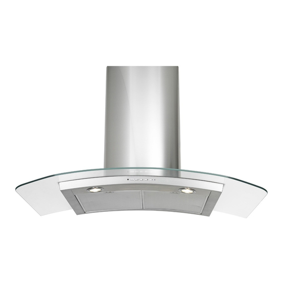
electrolux 5 YOUR APPLIANCE AND OPERATING INSTRUCTIONS YOUR APPLIANCE... -
Page 6: Operating Instructions
6 electrolux YOUR APPLIANCE AND OPERATING INSTRUCTIONS OPERATING INSTRUCTIONS The cooker hood is designed to extract unpleasant odours from the kitchen, it will not extract steam. The hood can be switched on pushing directly onto the requested speed without fi rstly having to select 0/1 button. FUNCTIONS 0/1 Light Turns lighting on and off. - Page 7 electrolux 7 To Operate Select the required fan speed and light if required. Recirculation recirculation mode contaminated air enters the cooker hood through the grease fi lters. The air is cleaned by passing through the charcoal fi lters before being passed back into the kitchen through the grilles in either side of the chimney stack.
-
Page 8: Maintenance And Cleaning
8 electrolux MAINTENANCE AND CLEANING MAINTENANCE AND CLEANING Before carrying out any maintenance or cleaning isolate the cooker hood from the mains supply. The cooker hood must be kept clean, as a build up of grease or fat can be a fi... - Page 9 electrolux 9 MAINTENANCE AND CLEANING Before carrying out any maintenance The fi lter is not washable and cannot or cleaning isolate the cooker hood be regenerated. It must be replaced from the mains supply. when led S1 fl ashes or at least every 4 months.
- Page 10 10 electrolux MAINTENANCE AND CLEANING Changing the halogen light • Remove the snap-on lamp cover by levering it from under the metal ring, supporting it with one hand. • Remove the halogen lamp from the lamp holder by pulling gently. •...
-
Page 11: Something Not Working
electrolux 11 SOMETHING NOT WORKING SOMETHING NOT WORKING If, having followed these instructions carefully, your cooker hood fails to work properly please carry out the following checks. Solution Symptom • Check the hood is connected to the The cooker hood will not start electricity supply. -
Page 12: Guarantee/Customer Service
12 electrolux GUARANTEE/CUSTOMER SERVICE GUARANTEE/CUSTOMER SERVICE Standard guarantee conditions the United Kingdom. We, Electrolux, undertake that if within • Appliances found to be in use within commercial environment, plus 12 months of the date of the purchase those which are subject to rental this Electrolux appliance or any part agreements. -
Page 13: Guarantee Conditions
electrolux 13 GUARANTEE CONDITIONS GUARANTEE CONDITIONS Customer Care European Guarantee For general enquiries concerning your This appliance guaranteed Electrolux appliance, or for further Electrolux in each of the countries information on Electrolux products listed at the back of this user manual, please contact our Customer Care for the period specifi... - Page 14 14 electrolux www.electrolux.com Albania +35 5 4 261 450 Rr. Pjeter Bogdani Nr. 7 Tirane Belgique/België/Belgien +32 2 363 04 44 Bergensesteenweg 719, 1502 Lembeek Česká republika +420 2 61 12 61 12 Budějovická 3, Praha 4, 140 21 Danmark +45 70 11 74 00 Sjællandsgade 2, 7000 Fredericia Deutschland...
-
Page 15: Installation Instructions
electrolux 15 INSTALLATION INSTRUCTIONS INSTALLATION INSTRUCTIONS It is dangerous to alter the specifi cations or attempt to modify this product in any way. Technical Information DIMENSIONS HEIGHT OF CANOPY: 70mm HEIGHT OF CHIMNEY: (UPPER SECTION) 415mm (LOWER SECTION) 700mm WIDTH OF CANOPY : 898mm DEPTH OF CANOPY: 650mm... -
Page 16: Electrical Connections
16 electrolux ELECTRICAL CONNECTIONS ELECTRICAL CONNECTIONS DOUBLE INSULATED DO NOT EARTH Electrical Requirements This appliance is fi tted with a 2 core Any permanent electrical installation mains cable and must be permanently must comply with the latest I.E.E. connected to the electricity supply Regulations and local Electricity Board double-pole switch... -
Page 17: Installing The Cooker Hood
electrolux 17 INSTALLING THE COOKER HOOD INSTALLING THE COOKER HOOD Please ensure that when the appliance is installed it is easily accessible to an engineer in the event of a breakdown. All installations must comply with the local authorities requirements for the discharge of exhaust air. - Page 18 18 electrolux INSTALLING THE COOKER HOOD The cooker hood is made up of the following components: Ref Qty Product Components Hood body, complete with controls, lighting, fan and fi lters. Telescopic Chimney comprising: 2.1 1 Upper section 2.2 1 Lower section 7.1 1 Telescopic frame complete with extroctor, consisting of:...
- Page 19 electrolux 19 INSTALLING THE COOKER HOOD Clearance Height When installed between adjoining wall The cooker hood is designed to be cabinets, the wall cabinets must not fi tted over a cooking appliance at the overhang the hob and the distance clearance heights stated, providing between the underside of the cabinet the maximum output of the appliance...
- Page 20 20 electrolux INSTALLING THE COOKER HOOD Drilling the Ceiling/Support Shelf • Use a plumb line to mark the centre of the hob on the ceiling/support shelf. • Place the drilling template 21 provided on the ceiling/support shelf, making sure that the template is in the correct position by lining up the axes of the template with those of the hob.
- Page 21 electrolux 21 INSTALLING THE COOKER HOOD Fixing the Frame • Loosen the two screws fastening the lower chimney and remove this from the lower fra me. • Loosen the two screws fastening the upper chimney and remove this from the upper fra me. If you wish to adjust the height of the frame, proceed as follows: •...
- Page 22 22 electrolux INSTALLING THE COOKER HOOD Extraction The cooker hood is more effective when used in the extraction mode (ducted to the outside). Venting kits may be purchased through your retailer or DIY store, and must be ducted to an outside vent of Ø125mm (5”) or Ø150mm (6”).
- Page 23 electrolux 23 INSTALLING THE COOKER HOOD Ducting Connection Connect the ducting chosen to: • the Ø150mm ducting spigot on top of the motor housing, or the Ø150- 120mm ducting spigot item 9 and secure using the jubilee clips item • A Ø120-125mm collar item 9.1 is provided to fi...
- Page 24 24 electrolux INSTALLING THE COOKER HOOD Chimney Stack The chimney consists of two sections. The lower chimney measures 700mm and the upper chimney (with the recirculation grilles on either side) measures 415mm. The overall installed measurement is min. 810 - max 1050mm.
- Page 25 electrolux 25 Electrical Connection • Connect the Hood to the Mains power supply, inserting a two-pole Switch with a contact aperture of at least 3 mm. • Remove the Metal grease fi lters (see par. on “Maintenance”) and make sure that the power supply Cable is properly inserted in the Suction fan socket.
- Page 26 electrolux 26...
- Page 28 www.electrolux.com 436003745_01 - 070410...