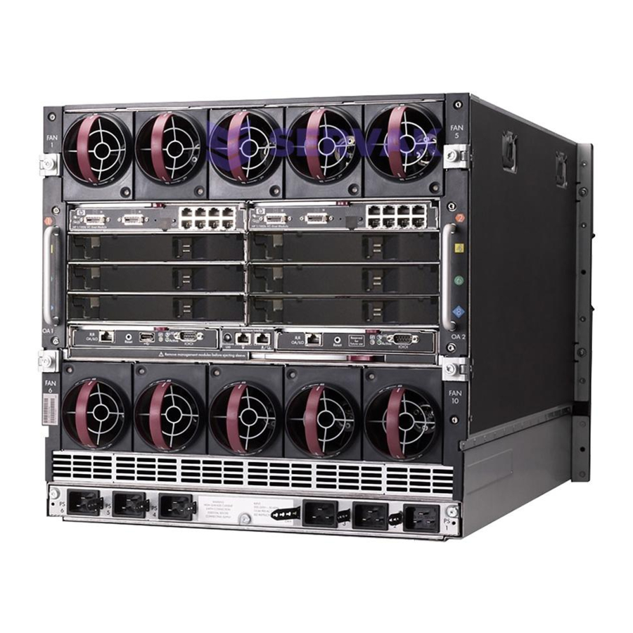
HP BladeSystem c7000 Maintenance And Service Manual
Bladesystem c7000 carrier-grade enclosure
Hide thumbs
Also See for BladeSystem c7000:
- Setup and installation manual (103 pages) ,
- Maintenance and service manual (80 pages) ,
- Quickspecs (43 pages)
Table of Contents

Related Manuals for HP BladeSystem c7000


Summary of Contents for HP BladeSystem c7000
- Page 1 HP BladeSystem c7000 Carrier-Grade Enclosure Maintenance and Service Guide Abstract This document contains specific information that is intended for users of this HP product. HP Part Number: 5900-2653 Published: February 2013 Edition: 2...
- Page 2 © Copyright 2007 – 2013 Hewlett-Packard Development Company, L.P. The information contained herein is subject to change without notice. The only warranties for HP products and services are set forth in the express warranty statements accompanying such products and services. Nothing herein should be construed as constituting an additional warranty. HP shall not be liable for technical or editorial errors or omissions contained herein.
-
Page 3: Table Of Contents
Contents 1 Overview....................5 This manual supplements other manuals..................5 2 Parts catalog....................6 HP BladeSystem c7000 Carrier-Grade Enclosure components............6 Seismic Rack components......................6 Seismic Rack options.........................6 3 Removal and replacement procedures............7 Required tools..........................7 Safety considerations........................7 Preventing electrostatic discharge...................7 Warning and caution messages.....................8 Rack doors..........................8 Rack side panels........................9... - Page 4 Subscription service......................27 Documentation feedback....................27 Installing HP Insight Remote Support Software................28 Related information.........................28 Typographic conventions......................28 A Alternate-Sized site cables.................30 Required documentation......................30 Recommended site power cables....................30 Recommended grounding cables....................30 Requirements for using alternate-sized site power or ground cables..........30 B Acronyms and abbreviations..............32 Index......................33...
-
Page 5: Overview
This manual is not intended as a standalone document. This manual is written as a supplement to manuals that describe other similar products, and you will need some of the documentation for these products to complete the tasks described in this manual. The HP Carrier-Grade BladeSystems are closely related to the commercial HP BladeSystem products. -
Page 6: Parts Catalog
Seismic Rack options In addition to the standard racks, HP also provides rack options to complement or complete your rack solution. Some of these options are necessary for full NEBS compliance. Part Number (Seismic Rack... -
Page 7: Removal And Replacement Procedures
3 Removal and replacement procedures NOTE: The HP BladeSystem c7000 Carrier-Grade Enclosure is similar to the HP BladeSystem c7000. Refer to the HP BladeSystem c7000 Enclosure Maintenance and Service Guide for the following removal and replacement procedures: Server blades Device bay shelves and shelf blanks... -
Page 8: Warning And Caution Messages
Warning and caution messages WARNING! To reduce the risk of personal injury or damage to equipment, heed all warnings and cautions throughout the installation instructions. WARNING! To reduce the risk of personal injury or damage to the equipment, you must adequately support enclosures during installation and removal. -
Page 9: Rack Side Panels
Pull down on the spring-loaded handles on the hinge assembly at the top of the door until the small pin securing the door to the hinge retracts. Move the top of the door away from the rack until the spring-loaded pin is free of the hinge assembly. -
Page 10: Breaker Panel
Verify that the power circuit breakers are switched off before handling the power cables. IMPORTANT: The breaker panel safety marking is for trained personnel only. HP does not recommend that untrained individuals service the breaker panel, breaker, or power cables. IMPORTANT: HP recommends that two people remove the breaker panel from the rack. -
Page 11: Servicing An Individual Breaker
Switch the breaker on. DC Power Supply or power supply blank To remove the component: NOTE: To access all power supply bays, slide the HP BladeSystem Insight Display to the right or left. Press the release button. Pull down the handle. -
Page 12: Dc Input Module
NOTE: Before removing the DC input module, you must power down the server blades and enclosure. For more information on these procedures, see the HP BladeSystem c7000 Enclosure Maintenance and Service Guide. Switch all breakers to the Off position in the breaker panel or site power panel. -
Page 13: Cable Management Tray
Remove the DC input module. To replace the component, reverse the removal procedure. Cable Management Tray Remove the screws, and slide the cable management tray out of the mounting rails. NOTE: If you have any difficulty sliding the cable management tray out of the mounting rails, loosen the screws that hold the rail brackets and then slide the tray out. -
Page 14: Cable Management System
Remove the four middle screws in the rear brace. From the front, remove the screws from the top brace, and then slide the top brace from the rack. Remove the screws, remove the two rear brackets, and remove and the rear brace. Remove the cage nuts from all four mounting rails. -
Page 15: Rack Mount
Remove the cage nuts from the rear mounting holes. To replace the component, reverse the removal procedure. Rack Mount NOTE: The U locations are noted in the following procedure for enclosures installed in the lower portion of the rack. When installing multiple enclosures into the rack, use the U locations in parentheses for the top enclosure. -
Page 16: Cabling
Cable management CAUTION: Gigabit Ethernet ports (intrabuilding ports) of the HP BladeSystem c7000 Carrier-Grade system require the use of shielded Cat5e cables grounded at both ends. The intrabuilding ports of the equipment are suitable for connection only to intrabuilding, unexposed wiring, or cabling. Do not connect the intrabuilding ports of the equipment metallically to interfaces that connect to the outside plant or its wiring. -
Page 17: Securing Cables
Item Description U14.5 Route signal and power cables through the top of the rack, directly above the signal and power routing areas. Route left cables out of the top left of the rack. Route right cables out of the top right of the rack. - Page 18 Secure each guide to the cable management system frame. You can also use hook-and-loop straps to fasten cables to the rack. Cabling...
-
Page 19: Breaker Panel Cabling
Breaker Panel cabling There are two cable options available: BLc2.0 cable—Connects the upper breaker panel (U35-U36) to the lower enclosure DC input module (U1-U10). BLc1.3 cable—Connects the lower breaker panel to the upper enclosure DC input module. Each cable option contains six pairs of red and black cables. The ends of each cable are different. The 90-degree cable end connects to the breaker panel. -
Page 20: Dc Input Module Cabling
DC Input Module cabling Cable repair If there is fiber cable that is not easily removed from the system: Disconnect both of the cable ends and cut cable several inches away from each connector Route new cable over the top of the old fiber cable, observing all routing rules in “Cabling”... -
Page 21: Diagnostic Tools
To obtain the guide, see any of the following sources and then select the HP ProLiant Servers Troubleshooting Guide: The server-specific Documentation CD. -
Page 22: Onboard Administrator
If an error occurs, the Onboard Administrator displays an error message on the Insight Display. In addition, the Onboard Administrator also displays error messages in email alerts and SNMP traps, if this feature is configured. For more information, see the HP BladeSystem Onboard Administrator User Guide. -
Page 23: Component And Led Identification
6 Component and LED identification DC Input Module components Terminal block Ground stud (4x) Case screw (4x) -48V (Power) Captive screw (3x) RTN (Return) Terminal Block numbering DC Input Module components... -
Page 24: Power Supply Bay Numbering
Power Supply Bay numbering Power Supply LEDs Power LED 1 (green) Fault LED 2 (amber) Condition Power supply DC output on and OK DC present/standby output on Power supply failure No DC power to power supply Component and LED identification... -
Page 25: Specifications
7 Specifications Environmental specifications Specification Value Temperature range Operating 5°C to 40°C (41°F to 104°F) Non operating -30°C to 60°C (-22°F to 140°F) Short-term -5°C to 50°C (23°F to 122°F) Wet bulb temperature Operating 28ºC (82.4ºF) Non operating 38.7ºC (101.7ºF) Relative humidity (noncondensing) Operating 20% to 80%... -
Page 26: Enclosure Specifications
Unpacking area: When moving the cabinet off the shipping pallet, you need approximately 9 feet (2.74 meters) on one side of the cabinet to allow you to slide the pallet out from under the cabinet after the cabinet has been raised on the casters. Enclosure specifications Specification Value... -
Page 27: Support And Other Resources
(http://welcome.hp.com/country/ us/en/wwcontact.html.) In other locations, see the Contact HP worldwide (in English) webpage: http://welcome.hp.com/country/us/en/wwcontact.html. For HP technical support: In the United States, for contact options see the Contact HP United States webpage: (http:// welcome.hp.com/country/us/en/contact_us.html) To contact HP by phone: ◦... -
Page 28: Installing Hp Insight Remote Support Software
HP strongly recommends that you install HP Insight Remote Support software to complete the installation or upgrade of your product and to enable improved delivery of your HP Warranty, HP Care Pack Service or HP contractual support agreement. HP Insight Remote Support supplements... - Page 29 NOTE: A note contains additional information to emphasize or supplement important points of the main text. Typographic conventions...
-
Page 30: A Alternate-Sized Site Cables
This appendix provides information for customers who plan to use alternate-sized site power input cables and lugs to connect site power. The alternate-sized cables and lugs must be provided by the customer or the installation provider for the customer. HP does not provide these items to the customer. - Page 31 NEBS 40°C environment. NOTE: Alternate-sized cables and lugs must be provided by the customer or the customer’s installation provider. HP does not provide these items to the customer. Requirements for using alternate-sized site power or ground cables...
-
Page 32: B Acronyms And Abbreviations
B Acronyms and abbreviations Canadian Standards Association electrostatic discharge Federal Communications Commission International Electrotechnical Commission NEMA National Electrical Manufacturers Association NFPA National Fire Protection Association network interface controller NEBS Network Equipment–Building system power distribution unit serial attached SCSI unit identification unshielded twisted-pair Acronyms and abbreviations... -
Page 33: Index
HP website, electrostatic discharge, enclosure cabling, input module, Onboard administrator, parts list, power supply, LEDs, power supply blank, rack doors, rack mount, related documentation,...