Table of Contents
Advertisement
Quick Links
Advertisement
Table of Contents

Related Manuals for Bosch MPC-xxxx-B


Summary of Contents for Bosch MPC-xxxx-B
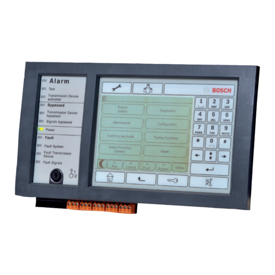
- Page 1 Panel Controller MPC-xxxx-B | FPA-1200-MPC Operation guide...
-
Page 3: Table Of Contents
Further functions Search Function/Element Reset In overview Operating elements Display elements Touch screen Standby display Display service department Operating principle Logging on and off 5.1.1 Logging in 5.1.2 Logging out Bosch Sicherheitssysteme GmbH Operation guide F.01U.076.969 | 6.0 | 2010.04... - Page 4 Displaying the individual detectors in a logical zone 8.4.7 Information about individual detectors 8.4.8 Displaying additional information Fire alarm Optical and acoustic signals Acknowledging a message Switching off internal buzzer F.01U.076.969 | 6.0 | 2010.04 Operation guide Bosch Sicherheitssysteme GmbH...
- Page 5 12.3.1 Using the menu 12.3.2 Via the status bar Diagnostics 13.1 Menu overview 13.2 Element details 13.3 Modules 13.4 Hardware 13.4.1 Address cards 13.4.2 Display 13.4.3 Serial Interface 13.4.4 CAN-Bus Bosch Sicherheitssysteme GmbH Operation guide F.01U.076.969 | 6.0 | 2010.04...
- Page 6 Input / Output Group Set Up 18.2.1 Adding or deleting elements 18.2.2 Change name 18.3 Group setting 18.3.1 Adding or removing 18.4 Detector sensitivity 18.5 Operator 18.5.1 Change password 18.5.2 Change universal password F.01U.076.969 | 6.0 | 2010.04 Operation guide Bosch Sicherheitssysteme GmbH...
- Page 7 Performing a fire drill 19.7 Alarm Counters Reset 20.1 Menu overview 20.2 Resetting elements Search Function/Element 21.1 Menu overview 21.2 Searching for function and device description 21.3 Search element Index Bosch Sicherheitssysteme GmbH Operation guide F.01U.076.969 | 6.0 | 2010.04...
-
Page 8: For Your Information
You can use this key to return from any submenu back to the start menu. NOTICE! The display changes from each menu element to the standby display if no entries are made within one minute. F.01U.076.969 | 6.0 | 2010.04 Operation guide Bosch Sicherheitssysteme GmbH... -
Page 9: Changing Language Display
– Catastrophes, influence of foreign bodies, and force majeure. Without the permission of Bosch, no changes or additions to or rebuilding of the panel including the panel controller may be undertaken. Rebuilding requires written permission. In case of non-approved constructional changes, any warranty claims against Bosch are voided. -
Page 10: For Your Safety
Do not use any pointed or sharp objects when operating the touch-sensitive display. This could damage the surface. Touch the touch screen with your finger (nail) or the stick attached to the left-hand side of the panel controller. F.01U.076.969 | 6.0 | 2010.04 Operation guide Bosch Sicherheitssysteme GmbH... -
Page 11: Maintenance
Skills required by personnel Display of event messages on the panel controller must only be processed by trained personnel. The system walktest and detector configuration must only be performed by trained, authorized personnel. Bosch Sicherheitssysteme GmbH Operation guide F.01U.076.969 | 6.0 | 2010.04... -
Page 12: All Functions At A Glance
Doorholder Transmission device Detector Extinguishing Annunciator system Logical zone More... -> Control element Interface module Show blocked devices – Display a list of all isolated elements – De-isolate isolated elements F.01U.076.969 | 6.0 | 2010.04 Operation guide Bosch Sicherheitssysteme GmbH... -
Page 13: Diagnostics
Serial interface: Display statistical data for the transmission. – CAN bus: Display status of CAN interfaces. Panel passport Display diagnostic information such as manufacturing data or software version of the panel controller. Bosch Sicherheitssysteme GmbH Operation guide F.01U.076.969 | 6.0 | 2010.04... -
Page 14: Maintenance
Display tested or untested elements (Not tested, Tested). Create / Change walktest group – Deleting or adding individual elements to specified walktest groups. – Delete all elements in a walktest group. F.01U.076.969 | 6.0 | 2010.04 Operation guide Bosch Sicherheitssysteme GmbH... -
Page 15: Change Language
Selected function fields such as Acknowledge or Reset Walktest Elements switched to walktest mode 3.4.7 Change device on V.24 Interface Assign a different device to the V.24 interface (Change device at V.24 interface). Bosch Sicherheitssysteme GmbH Operation guide F.01U.076.969 | 6.0 | 2010.04... -
Page 16: Configuration
Information on valid configuration of the system. Switching to day or night mode – Switch to day or night mode – In day mode: Set the reset time to night mode for the current day. F.01U.076.969 | 6.0 | 2010.04 Operation guide Bosch Sicherheitssysteme GmbH... -
Page 17: Further Functions
One of the two options will be offered, depending on how the panel is programmed: – Entering a master password that is valid indefinitely. This password cannot be changed and is available from the relevant Bosch branch on request –... -
Page 18: Search Function/Element
Search for an element in a list by entering the physical addressing. – By description: Search for an element in a list by entering the description. Reset Reset -> Event type Scope Logical zone Detector This panel F.01U.076.969 | 6.0 | 2010.04 Operation guide Bosch Sicherheitssysteme GmbH... -
Page 19: In Overview
Display a list of the networked panels and establish a remote connection with a networked panel (only valid for FPA-5000) or a remote keypad. Display the address of the service department, if programmed. "Home" key. Call up the start menu. Bosch Sicherheitssysteme GmbH Operation guide F.01U.076.969 | 6.0 | 2010.04... - Page 20 Otherwise, operation may be incorrect and people may be injured. To prevent possible misuse, remove the key after operation and store it in a secure location. F.01U.076.969 | 6.0 | 2010.04 Operation guide Bosch Sicherheitssysteme GmbH...
-
Page 21: Display Elements
Yellow x Main processor is malfunctioning Fault Yellow x Transmission device is malfunctioning Transmission Device Fault Signals Yellow External signaling device malfunctioning Touch screen Info bar Menu field Status bar Bosch Sicherheitssysteme GmbH Operation guide F.01U.076.969 | 6.0 | 2010.04... - Page 22 To select a main menu, touch the corresponding menu field on the touch screen. I Section 3 All functions at a glance, page 12, there is an overview of all main menus with their respective submenus. F.01U.076.969 | 6.0 | 2010.04 Operation guide Bosch Sicherheitssysteme GmbH...
-
Page 23: Standby Display
Depending on the configuration, additional information may be displayed. In a networked fire detection system, further icons can be displayed in the standby display depending on the network setting; see Section 6 Networked panels, page 34. Bosch Sicherheitssysteme GmbH Operation guide F.01U.076.969 | 6.0 | 2010.04... -
Page 24: Display Service Department
Display service department To display the address of the support service, please press: NOTICE! Information about the support service is only displayed if the information has already been entered in FSP-5000-RPS. F.01U.076.969 | 6.0 | 2010.04 Operation guide Bosch Sicherheitssysteme GmbH... -
Page 25: Operating Principle
On the display, each digit of the password is indicated with an asterisk so that nobody else can see the password. NOTICE! If you do not have your own password, enter the following numbers: 000000. Bosch Sicherheitssysteme GmbH Operation guide F.01U.076.969 | 6.0 | 2010.04... -
Page 26: Logging Out
In order to select a menu in the start menu, touch the field you require with your finger: The submenus are displayed. To select a submenu, gently touch the required field. F.01U.076.969 | 6.0 | 2010.04 Operation guide Bosch Sicherheitssysteme GmbH... -
Page 27: Returning To The Previous Selection
By number (no description shown): sorted in ascending order by numbers (logical or physical addressing); the numbers are depicted in number blocks without specification of the description. This list is only offered when detectors and logical zones are being selected. Bosch Sicherheitssysteme GmbH Operation guide F.01U.076.969 | 6.0 | 2010.04... -
Page 28: Scrolling Through Lists
A scrollbar appears on the status bar: Gently touch the horizontal line to jump to a particular place. To jump to the beginning of a list, touch: To jump to the end of a list, touch: F.01U.076.969 | 6.0 | 2010.04 Operation guide Bosch Sicherheitssysteme GmbH... -
Page 29: Various States Of List Fields
To scroll quickly using the scrollbar, select the "double arrow" key on the membrane keypad. The activated list field is marked. To search for and display a particular element; see Section 5.7 Search Function/Element, page 30. Bosch Sicherheitssysteme GmbH Operation guide F.01U.076.969 | 6.0 | 2010.04... -
Page 30: Assigning Mode
The list field of the element you are searching for is displayed at the beginning of the list. NOTICE! The more accurately the description of an element in the FSP-5000-RPS programming software is entered, the more successful the search by name will be. F.01U.076.969 | 6.0 | 2010.04 Operation guide Bosch Sicherheitssysteme GmbH... -
Page 31: Searching By Number
Only numbers can be entered in the search screen for the By number and By number (no description shown) lists. In the search screen for the list By description, both letters and numbers can be entered. Bosch Sicherheitssysteme GmbH Operation guide F.01U.076.969 | 6.0 | 2010.04... -
Page 32: Changing An Entry
The displays will now be shown in the selected language. NOTICE! After the system starts up following a power cut or battery failure, the default language defined in the FSP-5000-RPS programming software is set again. F.01U.076.969 | 6.0 | 2010.04 Operation guide Bosch Sicherheitssysteme GmbH... -
Page 33: Switching Between Status Bars
When addressing elements, there is a distinction between logical and physical addressing: Physical Elements Modules Loop Element Numbers Logical Elements Zone Element Numbers Examples: Element with physical addressing: 5.1 - 4 Element with logical addressing: 3 - 4 Bosch Sicherheitssysteme GmbH Operation guide F.01U.076.969 | 6.0 | 2010.04... -
Page 34: Networked Panels
C. There is a restricted remote connection with a networked panel or a remote keypad. F.01U.076.969 | 6.0 | 2010.04 Operation guide Bosch Sicherheitssysteme GmbH... -
Page 35: Network Addressing
C, the following icon is displayed: The networked panel B, with which panel A has already established a remote connection, in turn establishes a remote connection with a networked panel C. Bosch Sicherheitssysteme GmbH Operation guide F.01U.076.969 | 6.0 | 2010.04... -
Page 36: Terminating A Remote Connection With A Networked Panel
Select the isolated panels you require from the list. Select OK and confirm the subsequent query with OK. The isolation of the panel is lifted and a restricted connection is established. F.01U.076.969 | 6.0 | 2010.04 Operation guide Bosch Sicherheitssysteme GmbH... -
Page 37: Remote Keypad
The following functions cannot be executed from the remote keypad via a remote connection: – LED, foil, display and display touch test – Adjust touch screen Bosch Sicherheitssysteme GmbH Operation guide F.01U.076.969 | 6.0 | 2010.04... -
Page 38: Alarm
If an alarm delay is programmed for the detector generating the alarm, the alarm signal is not transmitted immediately and the message can be checked; see Section 8.2 Entry delays. F.01U.076.969 | 6.0 | 2010.04 Operation guide Bosch Sicherheitssysteme GmbH... -
Page 39: Entry Delays
The detector generating the alarm is reset after the first signal. The pre-alarm becomes the main alarm if a second detector in a different logical zone triggers an alarm. The transmission devices and signaling devices are activated. Bosch Sicherheitssysteme GmbH Operation guide F.01U.076.969 | 6.0 | 2010.04... -
Page 40: Day And Night Mode
For a detailed description of the various alarm delays, see Section 8.2 Entry delays. – Internal alarm An alarm that is reported to the panel in day mode. No transmission devices to the fire department are activated. F.01U.076.969 | 6.0 | 2010.04 Operation guide Bosch Sicherheitssysteme GmbH... -
Page 41: Alarm Message To The Panel
Section 9.4 Switching external signaling devices on and off, page 45. – Reset: Touch this button to reset all of the alarm messages shown on the display; see also Section 9.7 Resetting alarm message, page 47. Bosch Sicherheitssysteme GmbH Operation guide F.01U.076.969 | 6.0 | 2010.04... -
Page 42: Sequence Of The Alarm Messages
The latest message is always displayed at the end of the list. The message number (e.g. #008) of the latest message indicates the total number of logical zones in which one or more detectors have triggered an alarm. F.01U.076.969 | 6.0 | 2010.04 Operation guide Bosch Sicherheitssysteme GmbH... -
Page 43: Displaying The Individual Detectors In A Logical Zone
Date and time of the message – Physical and logical addressing of the detector – Only for LSN detectors: specification of the detector type – Action text (depending on the configuration) Bosch Sicherheitssysteme GmbH Operation guide F.01U.076.969 | 6.0 | 2010.04... -
Page 44: Fire Alarm
Select a message and then press Acknowledge. Only the selected message is acknowledged. NOTICE! If Go to Acknowledge is displayed, select this field in order to display the messages that have not yet been acknowledged. F.01U.076.969 | 6.0 | 2010.04 Operation guide Bosch Sicherheitssysteme GmbH... -
Page 45: Switching Off Internal Buzzer
In the Control field on the status bar, the number of control elements is reduced by the number of reset elements. To reset transmission devices, carry out the same steps, but select Transmission device in step 1. Bosch Sicherheitssysteme GmbH Operation guide F.01U.076.969 | 6.0 | 2010.04... -
Page 46: Triggering Fire Verification
If the alarm is not confirmed within this time, it will be forwarded to external stations. The time to investigate will be displayed. The alarm verification is initiated. Test the fire alarm onsite within the specified time. F.01U.076.969 | 6.0 | 2010.04 Operation guide Bosch Sicherheitssysteme GmbH... -
Page 47: Triggering Alarm Manually
Depending on the variant that is offered (see above), all elements that are not in the alarm state or all types of message within the same message type are reset. Bosch Sicherheitssysteme GmbH Operation guide F.01U.076.969 | 6.0 | 2010.04... -
Page 48: Bypassing Detectors
Select the alarm message you require. Select Bypass. NOTICE! The system does not transmit any information as to whether it was possible to bypass the selected element. To monitor the operation, please check the element. F.01U.076.969 | 6.0 | 2010.04 Operation guide Bosch Sicherheitssysteme GmbH... -
Page 49: Fault Message
To display the individual elements, select the element group you require. See also Section 10.2.5 Displaying individual elements of an element group, page 51. Bosch Sicherheitssysteme GmbH Operation guide F.01U.076.969 | 6.0 | 2010.04... -
Page 50: Trouble Message On The Panel
Address of the element group – Number of individual elements that have caused a fault in the respective element group – Message number – Additional information (e.g. the installation location, depending on the configuration) F.01U.076.969 | 6.0 | 2010.04 Operation guide Bosch Sicherheitssysteme GmbH... -
Page 51: The Newest Message
Displaying individual elements of an element group To display the individual elements in an element group, select the element group you require. The fault messages of the individual elements are listed. Bosch Sicherheitssysteme GmbH Operation guide F.01U.076.969 | 6.0 | 2010.04... -
Page 52: Information About Individual Elements
Action text (depending on the configuration) Select OK to return to the list of all fault messages. Reset, see Section 10.3 Resetting malfunction message, page 53. Block, see Section 10.4 Isolating an element, page 53. F.01U.076.969 | 6.0 | 2010.04 Operation guide Bosch Sicherheitssysteme GmbH... -
Page 53: Signals
Select the fault message you require. Select Block. CAUTION! The system does not transmit any information as to whether it was possible to isolate the selected element. To monitor the operation, check the element. Bosch Sicherheitssysteme GmbH Operation guide F.01U.076.969 | 6.0 | 2010.04... -
Page 54: Bypass
A list of the detectors is displayed. Refer to Section 5.6.1 Scrolling through lists, page 28 for information on how to scroll forward and backward through the list. Select the required list fields. The list fields are marked. F.01U.076.969 | 6.0 | 2010.04 Operation guide Bosch Sicherheitssysteme GmbH... -
Page 55: Displaying And Un-Bypassing Bypassed Element Groups
Select the element category you require, e.g. Detector. A list of all bypassed detectors is displayed: To un-bypass bypassed elements: Select the element you require. Select Un-bypass. The element is un-bypassed. Bosch Sicherheitssysteme GmbH Operation guide F.01U.076.969 | 6.0 | 2010.04... -
Page 56: Via The Status Bar
To un-bypass the buzzer again, select Unbypass buzzer in step 4. NOTICE! If you switch the internal buzzer off permanently, no acoustic signal will sound on the panel in the event of an alarm or fault! F.01U.076.969 | 6.0 | 2010.04 Operation guide Bosch Sicherheitssysteme GmbH... -
Page 57: Isolate
A C after a detector means that this detector is part of a closed group and cannot be isolated individually. In order to isolate a detector marked in this way, please select Logical zone in step 3. Bosch Sicherheitssysteme GmbH Operation guide F.01U.076.969 | 6.0 | 2010.04... -
Page 58: Displaying List Of All Isolated Elements
Select the list field you require, e.g. Detector. A list of all isolated elements is displayed. To de-isolate isolated elements: Select the element you require. Select Un-block. The element is de-isolated. F.01U.076.969 | 6.0 | 2010.04 Operation guide Bosch Sicherheitssysteme GmbH... -
Page 59: Diagnostics
The numbers before the module names indicate the slot of the module on the panel. Select the list field you require. On the display, various possibilities for selection are offered: Bosch Sicherheitssysteme GmbH Operation guide F.01U.076.969 | 6.0 | 2010.04... -
Page 60: Modules
Select the information option you require, e.g. Module status. Diagnostic information about the module status is displayed. A status bar appears. Select the arrow keys to display further information. Select Refresh to update data if necessary. F.01U.076.969 | 6.0 | 2010.04 Operation guide Bosch Sicherheitssysteme GmbH... -
Page 61: Hardware
Select Diagnostics in the start menu Hardware Display Select Display test. Line by line, the display turns a dark color from the top to the bottom and then changes again from black to white. Bosch Sicherheitssysteme GmbH Operation guide F.01U.076.969 | 6.0 | 2010.04... -
Page 62: Serial Interface
– Address – CAN ID – Production date – BOM revision – PCBA material number – Material number – Software version – Build type – Build number – MAC address F.01U.076.969 | 6.0 | 2010.04 Operation guide Bosch Sicherheitssysteme GmbH... -
Page 63: Led Test On Modules
2, as the distance from node 1 to node 3 is 2 nodes including the target node; see illustration. A value = 0 means that the node cannot be reached via this interface. Bosch Sicherheitssysteme GmbH Operation guide F.01U.076.969 | 6.0 | 2010.04... -
Page 64: Electro-Acoustic Systems
Emergency (yes/no) – Failure (yes/no) – Internal supervision (yes/no) – Supervision time (sec). – Boot up phase is finished (yes/no) – Failure at Controller (yes/no) – Failure at Router (yes/no) F.01U.076.969 | 6.0 | 2010.04 Operation guide Bosch Sicherheitssysteme GmbH... -
Page 65: Maintenance
Select Maintenance from the start menu Change language A list of the languages which can be selected is displayed. Select the language you require. The displays are displayed in the selected language. Bosch Sicherheitssysteme GmbH Operation guide F.01U.076.969 | 6.0 | 2010.04... -
Page 66: Activate Outputs
To end activation of the selected elements: Select Maintenance from the start menu Activate transmission device Select the list fields of the activated transmission devices. Select Off. The transmission devices are no longer activated. F.01U.076.969 | 6.0 | 2010.04 Operation guide Bosch Sicherheitssysteme GmbH... -
Page 67: Detector Removal
To un-bypass the buzzer again, select Unbypass buzzer in step 2. NOTICE! If you switch the internal buzzer off permanently, no acoustic signal will sound on the panel in the event of an alarm or fault! Bosch Sicherheitssysteme GmbH Operation guide F.01U.076.969 | 6.0 | 2010.04... -
Page 68: Maintenance - Walktest
New elements can be added to a group, and elements that have already been added can be removed. NOTICE! Even if the elements in a group (e.g. January) have been completely deleted, this group will still be displayed in the list. F.01U.076.969 | 6.0 | 2010.04 Operation guide Bosch Sicherheitssysteme GmbH... -
Page 69: Adding Or Deleting Elements
Select this function field to delete one or more elements. Only elements from the selected walktest group are displayed. Select an element. The element is marked. Select Delete. The selected element is deleted from the group. Bosch Sicherheitssysteme GmbH Operation guide F.01U.076.969 | 6.0 | 2010.04... -
Page 70: Starting And Ending Walktest
(optical, chemical or thermal) of the detectors you are testing, or select Simultaneous walktest to test combination detectors using a test device with combined trigger substances for simultaneous testing of multiple sensors. F.01U.076.969 | 6.0 | 2010.04 Operation guide Bosch Sicherheitssysteme GmbH... -
Page 71: Ending The Walktest
Select Not tested to display the elements that showed no reaction during the test or that have not been tested. – Select Tested to display the elements that were tested and showed a reaction. Bosch Sicherheitssysteme GmbH Operation guide F.01U.076.969 | 6.0 | 2010.04... -
Page 72: Assigning Tested Elements To A Walktest Group
Select Add to walktest group to assign the tested elements from the current walktest to a selected walktest group. – Select Overwrite walktest group to replace the elements in the selected walktest group with the tested elements from the current walktest. F.01U.076.969 | 6.0 | 2010.04 Operation guide Bosch Sicherheitssysteme GmbH... -
Page 73: Maintenance - History Log
A list of all fault messages is displayed. The events are sorted in ascending order by date and time. The fault messages are numbered chronologically. The leading number indicates the sequence in which the fault messages were received. Bosch Sicherheitssysteme GmbH Operation guide F.01U.076.969 | 6.0 | 2010.04... -
Page 74: Change Filter
All events with the selected date are displayed in the list. Print Print the complete displayed list or only a part of it. Exit End the entry and switch to the menu overview of the Maintenance menu. F.01U.076.969 | 6.0 | 2010.04 Operation guide Bosch Sicherheitssysteme GmbH... -
Page 75: Printing Out Data
A list of the printers that can be selected is displayed. Select a printer. Select Print. The list is printed. Event numbers To display the event numbers again: Select Show event numbers. To exit the display, press the "Back" key. Bosch Sicherheitssysteme GmbH Operation guide F.01U.076.969 | 6.0 | 2010.04... -
Page 76: Day And Night Mode
It is only possible to switch to day mode manually. There are two ways to switch between day and night mode: – Switching over via the menu – Switching via the status bar F.01U.076.969 | 6.0 | 2010.04 Operation guide Bosch Sicherheitssysteme GmbH... -
Page 77: Showing Details
"day mode" or "night mode" icon on the status bar. Select Show details. A list of all logical zones that are switched to day mode is displayed. Bosch Sicherheitssysteme GmbH Operation guide F.01U.076.969 | 6.0 | 2010.04... -
Page 78: Changing The Time For Resetting To Night Mode
Enter the numbers you require. Refer to Section 5.8 Entering numbers and text, page 31 for information on how to enter numbers. Select OK to confirm the entry or Cancel to cancel the operation. F.01U.076.969 | 6.0 | 2010.04 Operation guide Bosch Sicherheitssysteme GmbH... -
Page 79: Configuration
Add: Display all elements that have not yet been assigned to an input group, and add individual elements. – Cancel: Cancel the operation. To change the name of the input group, see Section 18.2.2 Change name, page 81. Bosch Sicherheitssysteme GmbH Operation guide F.01U.076.969 | 6.0 | 2010.04... - Page 80 Select this function field to delete one or more elements. Only elements from the selected input group are displayed. Select an element. The element is marked. Select Delete. The selected element is deleted from the group. F.01U.076.969 | 6.0 | 2010.04 Operation guide Bosch Sicherheitssysteme GmbH...
-
Page 81: Change Name
Select the list field you require. You can choose between various options. To add elements to a group or remove elements from it, see Section 18.3.1 Adding or removing, page 81. Bosch Sicherheitssysteme GmbH Operation guide F.01U.076.969 | 6.0 | 2010.04... -
Page 82: Detector Sensitivity
Select the selection field of the detector sensitivity you require. A checkmark is set in this field. Select OK to confirm the selection or Cancel to cancel the operation. The selected detector sensitivity is confirmed for the detector. F.01U.076.969 | 6.0 | 2010.04 Operation guide Bosch Sicherheitssysteme GmbH... -
Page 83: Operator
On the display, each digit of the password is indicated with an asterisk so that nobody else can see the password. Select OK to confirm the entry or Cancel to cancel the operation. The entry is confirmed. Bosch Sicherheitssysteme GmbH Operation guide F.01U.076.969 | 6.0 | 2010.04... -
Page 84: Set Default Password
Configuration and additional information on this – Date – Configuration version (Config. version) – Number – Name – IP address – Scope – Country – Time zone – Menu name F.01U.076.969 | 6.0 | 2010.04 Operation guide Bosch Sicherheitssysteme GmbH... -
Page 85: Further Functions
One of the two options will be offered, depending on how the panel is programmed: – Entering a master password that is valid indefinitely. This password cannot be changed and is available from the relevant Bosch branch on request. –... -
Page 86: Enter The Master Password That Is Valid Indefinitely
To create a connection to the teleservice: Select Further functions in the start menu Remote access Enable call The Remote Access can now call the system. Afterwards, the connection is disconnected. F.01U.076.969 | 6.0 | 2010.04 Operation guide Bosch Sicherheitssysteme GmbH... -
Page 87: Change Password
If an alarm or a fault/supervisory alarm is sounded during a fire drill, the panel controller reacts as described in the table below: Fire alarm Fault/ supervisory alarm The drill signaling devices are switched off. The drill is automatically terminated. Bosch Sicherheitssysteme GmbH Operation guide F.01U.076.969 | 6.0 | 2010.04... -
Page 88: Alarm Counters
Confirm the message "Attention: Counter will be reset" with OK to reset the alarm counter to 0 or select Cancel to cancel the operation. NOTICE! In order to reset alarm counters, you need authorization level 4. F.01U.076.969 | 6.0 | 2010.04 Operation guide Bosch Sicherheitssysteme GmbH... -
Page 89: Reset
If a list field is marked with an R, the process of resetting is not yet complete for this element: TEXT If an element cannot be reset, it will continue to be displayed in the list. After the elements have been reset, the standby display is displayed. Bosch Sicherheitssysteme GmbH Operation guide F.01U.076.969 | 6.0 | 2010.04... -
Page 90: Search Function/Element
What is displayed depends on: – the message types (e.g. fault, alarm etc.) that can be assigned to this element. – the mode (e.g. bypassed, reset etc.) that the selected element is in. F.01U.076.969 | 6.0 | 2010.04 Operation guide Bosch Sicherheitssysteme GmbH... -
Page 91: Index
Input group, deleting elements 79 Description, search by 30 Input/output group, changing name 81 Detector removal 67 Interfaces 63 Detector sensitivity 82 Intermediate alarm storage 39 Diagnostics 59 IP Address 84 Bosch Sicherheitssysteme GmbH Operation guide F.01U.076.969 | 6.0 | 2010.04... - Page 92 Rename elements 84 Reset counters 88 Resetting alarm message 47 Resetting external signaling devices 45 Resetting, detectors 89 Resetting, elements 89 Resetting, message type 89 Resetting, scope 89 Resetting, this panel 89 F.01U.076.969 | 6.0 | 2010.04 Operation guide Bosch Sicherheitssysteme GmbH...
- Page 94 Bosch Sicherheitssysteme GmbH Werner-von-Siemens-Ring 10 85630Grasbrunn Germany www.boschsecurity.com © Bosch Sicherheitssysteme GmbH, 2010...