Dell Dimension E521 Service Manual
Hide thumbs
Also See for Dimension E521:
- Setting up (2 pages) ,
- Owner's manual (158 pages) ,
- Owner's manual (164 pages)
Table of Contents
Advertisement
Dell™ Dimension™ E521 Service Manual
Before You Begin
About Your Computer
Technical Overview
Specifications
Advanced Troubleshooting
System Setup
Removing and Installing Parts
Model DCSM
Notes, Notices, and Cautions
NOTE:
A NOTE indicates important information that helps you make better use of your computer.
NOTICE:
A NOTICE indicates either potential damage to hardware or loss of data and tells you how to avoid the problem.
CAUTION:
A CAUTION indicates a potential for property damage, personal injury, or death.
If you purchased a Dell™ n Series computer, any references in this document to Microsoft® Windows® operating systems are not applicable.
Information in this document is subject to change without notice.
© 2006 Dell Inc. All rights reserved.
Reproduction in any manner whatsoever without the written permission of Dell Inc. is strictly forbidden.
Trademarks used in this text: Dell, the DELL logo, and Dimension are trademarks of Dell Inc.; Microsoft and Windows are registered trademarks of Microsoft Corporation; AMD,
Athlon, a n d Sempron are trademarks of Advanced Micro Devices, Inc.
Other trademarks and trade names may be used in this document to refer to either the entities claiming the marks and names or their products. Dell Inc. disclaims any
proprietary interest in trademarks and trade names other than its own.
September 2006 Rev. A00
Advertisement
Table of Contents

Related Manuals for Dell Dimension E521


Summary of Contents for Dell Dimension E521
- Page 1 Athlon, a n d Sempron are trademarks of Advanced Micro Devices, Inc. Other trademarks and trade names may be used in this document to refer to either the entities claiming the marks and names or their products. Dell Inc. disclaims any proprietary interest in trademarks and trade names other than its own.
-
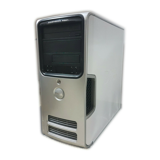
Page 2: About Your Computer
Removing the Computer Cover. release location of Use the Service Tag to identify your computer when you access the Dell Service Tag Support website or call technical support. CD or DVD Press to eject a disk from the CD or DVD drive. -
Page 3: Back View Of The Computer
NOTICE: Ensure that there is a minimum of two inches of space between all vents and any object near these vents. NOTICE: Keep the vent area clean and dust-free to ensure that the computer is adequately ventilated. Use only a dry cloth to clean the vent area to avoid water damage to the computer. - Page 4 network speed to 10 Mbps to ensure reliable operation. network activity Flashes a yellow light when the computer is transmitting or light receiving network data. A high volume of network traffic may make this light appear to be in a steady "on" state. surround Use the black surround connector to attach multichannel-capable connector...
-
Page 5: Diagnostic Lights
A possible BIOS failure has occurred; the Run the BIOS Recovery utility, wait for recovery completion, and then restart the computer. computer is in the recovery mode. A possible processor failure has Contact Dell (see "Contacting Dell" in your Owner's Manual). occurred. -
Page 6: Beep Codes
One possible beep code consists of one long beep and then two short beeps. This beep code tells you that the computer encountered a memory test failure. If your computer beeps during start-up: 1. Write down the beep code. 2. Run the Dell Diagnostics to identify a more serious cause (see Dell Diagnostics). Code Cause 2 short, 1 long... - Page 7 A filename cannot contain any of the following characters: \ / : * ? " < > | — Do not use these characters in filenames. A required .DLL file was not found — The program that you are trying to open is missing an essential file. To remove and then reinstall the program: 1. Click the Start button, click Control Panel, and then click Add or Remove Programs. 2.
-
Page 8: Starting The Dell Diagnostics
The Quickboot feature changes the boot sequence for the current boot only. Upon restart, the computer boots according to the boot sequence specified in system setup. 4. At the Dell Diagnostics Main Menu, left-click with the mouse, or press <Tab> and then <Enter>, to select the test you want to run (see Dell Diagnostics Main Menu). -
Page 9: Dell Diagnostics Main Menu
If you cannot resolve the error condition, contact Dell (see "Contacting Dell" in your Owner's Manual). NOTE: The Service Tag for your computer is located at the top of each test screen. If you contact Dell, technical support will ask for your Service Tag. ... -
Page 10: Using Windows Xp Device Driver Rollback
If an exclamation point appears next to the device name, you may need to reinstall the driver or install a new driver. Reinstalling Drivers NOTICE: The Dell Support website at support.dell.com provides approved drivers for your Dell™ computer. If you install drivers obtained from other sources, your computer may not function properly. Using Windows XP Device Driver Rollback If a problem occurs on your computer after you install or update a driver, use Windows XP Device Driver Rollback to replace the driver with the previously installed version. -
Page 11: Resolving Software And Hardware Incompatibilities
10. Click Finish and restart your computer. Resolving Software and Hardware Incompatibilities If a device is not detected during the operating system setup or is detected but incorrectly configured, you can use the Hardware Troubleshooter to resolve the incompatibility. To resolve incompatibilities using the Hardware Troubleshooter: ... -
Page 12: Before You Begin
Hold a component such as a processor by its edges, not by its pins. NOTICE: Only a certified service technician should perform repairs on your computer. Damage due to servicing that is not authorized by Dell is not covered by your warranty. - Page 13 NOTICE: To disconnect a network cable, first unplug the cable from your computer, and then unplug it from the network port or device. 2. Disconnect any telephone or telecommunication lines from the computer. 3. Disconnect your computer and all attached devices from their electrical outlets, and then press the power button to ground the system board. NOTICE: Before touching anything inside your computer, ground yourself by touching an unpainted metal surface, such as the metal at the back of the computer.
-
Page 14: Removing And Installing Parts
You have performed the steps in Turning Off Your Computer Before Working Inside Your Computer. You have read the safety information in your Dell™ Product Information Guide. A component can be replaced by performing the removal procedure in reverse order. You have the tools listed in Recommended Tools. -
Page 15: Memory Installation Guidelines
cover latch release computer cover back of computer bottom hinge tabs 4. Locate the three hinge tabs on the bottom edge of the computer. 5. Grip the sides of the computer cover and pivot the cover up, using the bottom hinge tabs as leverage points. ... -
Page 16: Addressing Memory With 4-Gb Configurations
If you remove your original memory modules from the computer during a memory upgrade, keep them separate from any new modules that you may have, even if you purchased the new modules from Dell. If possible, do not pair an original memory module with a new memory module. -
Page 17: Removing Memory
To prevent static damage to components inside your computer, discharge static electricity from your body before you touch any of your computer's electronic components. You can do so by touching an unpainted metal surface on the computer chassis. Your Dell™ computer provides the following slots for PCI and PCI Express cards: One PCI Express x16 card slot (SLOT1) -
Page 18: Installing A Pci Card
One PCI Express x1 card slot (SLOT2 Two PCI card slots (SLOT3, SLOT4) System Board Components for card slot location. PCI Cards Your computer supports two PCI cards. If you are installing or replacing a card, follow the procedures in the next section. If you are removing but not replacing a PCI card, see Removing a PCI Card. - Page 19 alignment bar fully seated card not fully seated card alignment guide bracket within slot bracket caught outside of slot 8. Before you close the card retention door, ensure that: The tops of all cards and filler brackets are flush with the alignment bar. The notch in the top of the card or filler bracket fits around the alignment guide.
-
Page 20: Removing A Pci Card
14. If you installed an add-in network adapter and want to use only the add-in network adapter, then disable the integrated network adapter: a. Enter system setup (see System Setup), go to Onboard Devices and select Integrated NIC, and then change the setting to Off. b. -
Page 21: Installing A Pci Express Card
NOTICE: To connect a network cable, first plug the cable into the network device and then plug it into the computer. 6. Replace the computer cover (see Installing the Computer Cover). 7. Reconnect the computer and devices to electrical outlets, and then turn them on. ... - Page 22 6. If you are replacing a card that is already installed in the computer, remove the card. Disconnect any cables connected to the card. Gently pull the securing tab, grasp the card by its top corners, and then ease it out of its connector. PCI Express x16 card 2 securing tab PCI Express x1 card...
-
Page 23: Removing A Pci Express Card
card retention door card retention mechanism release tabs (2) NOTICE: Do not route card cables over or behind the cards. Cables routed over the cards can prevent the computer cover from closing properly or cause damage to the equipment. NOTICE: To connect a network cable, first plug the cable into the network device and then plug it into the computer. -
Page 24: Removing The Drive Panel
8. Replace the computer cover (see Installing the Computer Cover). 9. Reconnect the computer and devices to electrical outlets, and then turn them on. 10. Remove any drivers required for the card as described in the card documentation. ... -
Page 25: Removing The Drive-Panel Insert
Removing the Drive-Panel Insert drive panel drive-panel insert tab drive-panel insert 1. Pull the drive-panel insert tab away from the drive panel insert to disengage the insert from the drive panel. 2. Without releasing the tab, pivot the drive-panel insert out and away from the drive panel. ... -
Page 26: Connecting Drive Cables
sliding plate lever sliding plate drive panel drive panel tabs (3) side hinges 2. Align the drive panel tabs with the side hinges. 3. Rotate the drive panel toward the computer until it snaps into place on the front panel. Drives The computer supports a combination of these devices: Up to two serial ATA hard drives... -
Page 27: Drive Interface Connectors
When you install a drive, you connect a DC power cable and a data cable to the back of the drive. power cable power input connector Drive Interface Connectors The drive cable connectors are keyed for correct insertion. Properly align the cable connector key on the cable and the drive before connecting. interface cable interface connector ... -
Page 28: Removing A Hard Drive
Removing a Hard Drive 1. Follow the procedures in Before You Begin. 2. Remove the computer cover (see Removing the Computer Cover). 3. Disconnect the power and data cables from the drive. NOTICE: Use the pull-tab to remove the data cable from your hard drive. serial ATA data cable power cable ... - Page 29 drive hard-drive bracket 4. Align the hard drive bracket with the guides in the hard drive bay. hard-drive bracket hard drive guide in hard-drive bay 5. Gently slide the drive into place until you feel a click or the drive is securely installed. Take care not to let the drive free-fall into the drive bay. ...
-
Page 30: Adding A Second Hard Drive
Adding a Second Hard Drive CAUTION: Before you begin any of the procedures in this section, follow the safety instructions in the Product Information Guide. CAUTION: To guard against electrical shock, always unplug your computer from the electrical outlet before removing the cover. NOTICE: To avoid damage to the drive, do not set it on a hard surface. -
Page 31: Removing A Floppy Drive
Removing a Floppy Drive 1. Follow the procedures in Before You Begin. 2. Remove the computer cover (see Removing the Computer Cover). 3. Remove the drive panel (see Removing the Drive Panel). power cable data cable 4. -
Page 32: Installing A Floppy Drive
Installing a Floppy Drive NOTE: In the event that the replacement or new floppy drive does not have shoulder screws, use the shoulder screws located within the drive panel insert. Otherwise, reuse the screws attached to the drive that you are replacing. ... -
Page 33: Removing A Media Card Reader
See the documentation that came with the drive for instructions on installing any software required for drive operation. 12. Enter system setup (see System Setup) and select the appropriate Diskette Drive option. 13. Verify that your computer works correctly by running the Dell Diagnostics (see Dell Diagnostics). Media Card Reader CAUTION: Before you begin any of the procedures in this section, follow the safety instructions in the Product Information Guide. -
Page 34: Installing A Media Card Reader
drive release latch sliding plate Media Card Reader 5. Slide the drive latch release toward the bottom of the computer and, without releasing the drive latch release, slide the Media Card Reader out through the front of the computer. ... -
Page 35: Removing A Cd/Dvd Drive
Remove the Media Card Reader from its packaging. Remove the shoulder screws from the inside of the drive-panel insert and attach the screws to the new Media Card Reader. 5. Gently slide the Media Card Reader into place until you feel a click or feel the drive securely installed. Ensure that the Media Card Reader is installed before the FlexBay cable is connected. -
Page 36: Installing A Cd/Dvd Drive
power cable data cable 5. Slide the drive latch release toward the bottom of the computer and, without releasing the drive latch release, slide the CD/DVD drive out through the front of the computer. 6. If you are not replacing the drive, replace the drive panel insert (see Installing the Drive-Panel Insert). - Page 37 CD/DVD drive screws (3) 1. Follow the procedures in Before You Begin. 2. Remove the computer cover (see Removing the Computer Cover). 3. If you are installing a new drive, unpack the drive and prepare it for installation. Check the documentation that accompanied the drive to verify that the drive is configured for your computer.
-
Page 38: Replacing The Battery
Setup), and select the appropriate Drive option. See the documentation that came with the drive for instructions on installing any software required for drive operation. 13. Verify that your computer works correctly by running the Dell Diagnostics (see Dell Diagnostics). -
Page 39: Replacing The Power Supply
CAUTION: Before you begin any of the procedures in this section, follow the safety instructions located in the Product Information Guide. NOTICE: To prevent static damage to components inside your computer, discharge static electricity from your body before you touch any of your computer's electronic components. -
Page 40: Removing The Processor
14. Replace the computer cover (see Installing the Computer Cover). 15. Connect your computer and devices to an electrical outlet, and turn them on. 16. Verify that the computer works correctly by running the Dell Diagnostics (see Dell Diagnostics). Processor CAUTION: Before you begin any of the procedures in this section, follow the safety instructions located in the Product Information Guide. -
Page 41: Installing The Processor
7. Pull the release lever straight up until the processor is released. processor release lever socket NOTICE: Be careful not to bend any of the pins when you remove the processor. Bending the pins can permanently damage the processor. ... - Page 42 processor pin-1 indicator processor release lever socket NOTICE: To avoid damage, ensure that the processor aligns properly with the socket, and do not use excessive force when you install the processor. 5. Set the processor lightly in the socket and ensure that the processor is positioned correctly. ...
-
Page 43: Removing The I/O Panel
12. Replace the computer cover (see Installing the Computer Cover). 13. Connect your computer and devices to an electrical outlet, and turn them on. 14. Verify that the computer works correctly by running the Dell Diagnostics (see Dell Diagnostics). I/O Panel CAUTION: Before you begin any of the procedures in this section, follow the safety instructions in the Product Information Guide. -
Page 44: Installing The I/O Panel
4. Replace the computer cover (see Installing the Computer Cover). 5. Connect your computer and devices to an electrical outlet, and turn them on. 6. Verify that the computer works correctly by running the Dell Diagnostics (see Dell Diagnostics). Processor Fan CAUTION: Before you begin any of the procedures in this section, follow the safety instructions in the Product Information Guide. -
Page 45: Installing The Processor Fan
6. Rotate the heat sink assembly towards the rear of the computer, and then remove it from the computer. Lay the heat sink assembly down on its top, with the thermal grease facing upward. heat sink and fan shroud assembly captive screw housing (2) ... -
Page 46: Removing The System Board
3. Connect the processor fan cable to the system board (see System Board Components). 4. Install the heat sink assembly: a. Place the heat sink assembly back onto the heat-sink assembly bracket. b. Rotate the heat sink assembly down towards the computer base and ensure that the two captive screws are properly aligned with the holes in the system board. -
Page 47: Installing The System Board
Installing the Computer Cover). 10. Connect your computer and devices to an electrical outlet, and turn them on. 11. Verify that the computer works correctly by running the Dell Diagnostics (see Dell Diagnostics). Installing the Computer Cover ... - Page 48 1. Ensure that all cables are connected, and fold cables out of the way. 2. Ensure that no tools or extra parts are left inside the computer. 3. Align the bottom of the cover with the tabs located along the bottom edge of the computer. ...
- Page 49 Athlon, a n d Sempron are trademarks of Advanced Micro Devices, Inc. Other trademarks and trade names may be used in this document to refer to either the entities claiming the marks and names or their products. Dell Inc. disclaims any proprietary interest in trademarks and trade names other than its own.
-
Page 50: Specifications
Back to Contents Page Specifications Dell™ Dimension™ E521 Service Manual Processor Processor type AMD Athlon™ 64 X2 dual-core processor AMD Athlon 64 processor AMD Sempron™ processor Level 2 (L2) cache Up to 1 MB per core Up to 256 KB for Sempron processors Memory Type 533-MHz, 667-MHz, 800-MHz (when available) DDR2... - Page 51 connector size 124 pins connector data width (maximum) 32 bits PCI Express connector one x1 connector size 36 pins connector data width (maximum) 1 PCI Express lane PCI Express connector one x16 connector size 164 pins connector data width (maximum) 16 PCI Express lanes ...
- Page 52 orange light — A good connection exists between a 100 Mbps network and the computer. off (no light) — The computer is not detecting a physical connection to the network. Network activity light (on integrated network yellow blinking light adapter) ...
-
Page 53: Entering System Setup
1. Turn on (or restart) your computer. 2. When the DELL logo appears, press <F2> immediately. NOTE: Keyboard failure may result when a key on the keyboard is held down for extended periods of time. To avoid possible keyboard failure, press and release <F2>... -
Page 54: System Setup Options
System Setup Options NOTE: Depending on your computer and installed devices, the items listed in this section may not appear, or may not appear exactly as listed. System Displays the System name, BIOS Version, Service Tag, Express Service Code, and Asset Tag. ... - Page 55 (On default) Video Primary Video Specifies which video controller is primary when two video controllers are present on the computer. Auto enables the add-in video controller. Onboard enables the integrated video controller. (Auto default) Video Memory This setting configures the amount of system memory that is reserved for the integrated video controller. The settings are Auto, 16MB, Size 32MB, 64MB, 128MB, or Off.
-
Page 56: Option Settings
S1 — sets the computer to a suspend state where the computer is running in a low-power mode (S3 default) S3 — sets the computer to a standby state where the power is reduced or turned off for most components; however, system memory remains active for both settings Maintenance Service Tag... -
Page 57: Changing Boot Sequence For Future Boots
1. If you are booting to a USB device, connect the USB device to a USB connector (see Front View of the Computer). 2. Turn on (or restart) your computer. 3. When F2 = Setup, F12 = Boot Menu appears in the upper-right corner of the screen, press <F12>. NOTE: Keyboard failure may result when a key on the keyboard is held down for extended periods of time. -
Page 58: Clearing Cmos Settings
The BIOS may require flashing when an update is available or when replacing the system board. 1. Turn on the computer. 2. Locate the BIOS update file for your computer at support.dell.com. 3. Click Download Now to download the file. ... - Page 59 4. If the Export Compliance Disclaimer window appears, click Yes, I Accept this Agreement. The File Download window appears. 5. Click Save this program to disk, and then click OK. The Save In window appears. 6. Click the down arrow to view the Save In menu, select Desktop, and then click Save. The file downloads to your desktop.
-
Page 60: Technical Overview
Back to Contents Page Technical Overview Dell™ Dimension™ E521 Service Manual Inside View of Your Computer System Board Components Power Supply DC Connector Pin Assignments Inside View of Your Computer floppy drive or Media Card Reader CD or DVD drive power supply system board hard drive ... -
Page 61: Power Supply Dc Connector Pin Assignments
fan connector processor socket (CPU) memory module connectors (FAN_CPU1) (DIMM_1, DIMM_2, DIMM_3, DIMM_4) power connector serial ATA drive serial ATA drive connectors (PW_12V_A1) connectors (SATA2, (SATA0, SATA1) SATA3) front-panel power connector line-in, line-out, microphone, side connector (POWER1) surround, center, and LFE (FRONTPANEL) connectors (AUDIO_6_STACK) 10 USB connectors (2) - Page 62 Black PS_PWRGOOD Gray P5AUX Purple V_12P0_DIG White V_12P0_DIG White +3.3 VDC Orange +3.3VDC/SE* Orange -12 VDC Blue Black PWR_PS_ON Green Black Black Black +5 VDC +5 VDC +5 VDC Black DC Power Connector P2 Pin Number Signal Name 18-AWG Wire Black...
- Page 63 Pin Number Signal Name 22-AWG Wire +5 VDC Black Black +12 VADC Yellow DC Power Connector P10 Pin Number Signal name 18-AWG Wire +12 VBDC White Black Black +5 VDC Back to Contents Page ...