Table of Contents
Advertisement
Available languages
Available languages
Advertisement
Table of Contents

Related Manuals for Craftsman 124.214000


Summary of Contents for Craftsman 124.214000
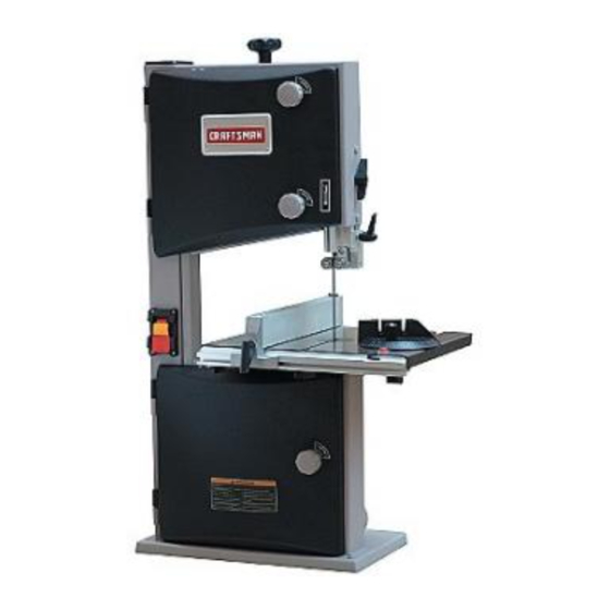
- Page 1 Operator's Manual tl ° 10" BAND SAW Model No. 124.214000 CAUTION: Read and follow all Safety Rules and Operating Instructions before First Use of this Product. Sears Brands Management Corporation Hoffman Estates, IL 60179 www.craftsma n.com...
- Page 2 16-25 PREPAREWORK AREA FOR JOB Keep work area clean. Cluttered work areas invite accidents. CRAFTSMAN ONE YEAR FULL WARRANTY Do not use power tools in dangerous environments. FOR ONE YEAR from the date of purchase, this product is Do not use power tools in damp or wet locations. Do not expose power tools to rain.
- Page 3 CAUTION: Do not attempt assembly if parts are miss- Safety goggles are available at SearsStores or Craftsman Outlets ing. Use this manual to order replacement parts. The machine is supplied partly assembled. Prior to use,...
- Page 4 Locate four hex bolts and four lock washers from the bag of loose parts. Mount the table to the upper table trunnion and install a bolt with washer in each hole, and then tighten with adjustable wrench. CENTERINGTHE TABLE Loosen the four hex bolts mounting the table to the upper table trunnion (see Figure 3).
- Page 5 STABILIZE MACHINE To ensure sufficient upright stability of the machine it should be bolted to floor, bench or worktable. MOTOR this purpose 6mm holes are provided in the The band saw is supplied with a 1/3 HP Motor. machine's base. Mounting hardware not provided.
- Page 6 (or green and yellow) wire to a live terminal. The Craftsman 10 inch Bench Top Band Saw features weld- ed steel frame construction and a solid cast iron table...
- Page 7 CORRECT HAND PLACEMENT 3effect Slowly feed the work piece t owards thesaw blade putting 0 nly light p ressure onit.With both hands, firmly h01d thework piece d own o nthe table, and feed ittowards the saw blade s lowly. The saw blade c uts onacontinuous downstroke.
- Page 8 TRACKINGTHE SAW BLADE Adjust the rear roller guide to be just clear of the back of the saw blade by unlocking the guide adjust- Set the tracking of the saw blade before setting ing screw (B). blade guides. When the correct adjustment is reached, lock the...
- Page 9 BLADETHICKNESS Blade thickness describes the distance between sides of blade. A thicker blade has more rigidity stronger teeth. A narrow thick blade is used to cut curves while a wide thin blade is used to make long, straight cuts. BLADE PITCH Pitch describes number of teeth...
- Page 10 MITER GAUGE WARNING: Any attempt to repair the motor may cre- ate a hazard unless repair is done by qualified service Use miter gauge for securing and holding workpiece technician. at desired angle to produce angled cuts. Use scale to adjust gauge to desired angle. Repairs are available at a Sears Parts and Repair Service Center.
- Page 11 SYMPTOM CORRECTIVE ACTION POSSIBLE CAUSE(S) The machine does not 1. No power supply. 1. Check the cable for breakage. work when switched 2. Defective switch. 2. Replace the lock switch. 3. Defective motor. 3. Replace the motor. The saw blade does 1.
- Page 12 Model124.214000 Figure 23 - Replacement Parts Illustration...
- Page 13 DESCRIPTION PART DESClPTION DESCRIPTION PART PART Hex.Bolt M6XI 2 ldL20061101-001S 1-M6X12GB5781Z 1-JL200611O1-081S Knurled Knob Cap Blade Tracking Knob Cap Table Trunnion Lower ldL20061102-001S Hex. Screw M6X45 1-JL22030001 1-M6X45GB5781Z Blade Tracking Knob Body 1-M6X60GB5781Z Hex. Bolt M6X60 1-M6X16GB14Z 1-JL20061102-081S Carriage Bolt M6XI 6 Knurled Knob Body 1-M6GB6172Z Hex.
- Page 14 DESCRIPTION PART PART DESCIPTION PART DESCRIPTION Knob I -JL60040003-001S 1-M6G B6172Z Hex. Nut M6 1-M14GB6171Z Hex. Nut M14 I-JL22042004 1-J L20061102-081S 1-JL22021004 Adjusting Shaft Knurled Knob Body Star Lock Cap HexSocketSetScrewM6X1 I-M6XIOGB80B 1-M6X40GB5781Z Hex. Screw M6X45 1-JL22021002 Shaft Mount I-JL22043001 1-J L20061101-081S 1-JL22021001-081Z Blade Tensioner...
- Page 15 NOTES...
- Page 16 PREPAREEL AREA DETRABAJO PARA LATAREA A REALIZAR GARANTIA COMPLETA DE UN ANO PARA Mantenga el _rea de trabajo limpia. Las Meas de trabajo HERRAMIENTA CRAFTSMAN desordenadas atraen accidentes. Siesta herramienta Craftsman fallara por causa de defectos No use herramientas...
- Page 17 Mantenga todas las partes listas para funcionar. Revise el protector u otras piezas para determinar si funcionan correc- tamente y hacen el trabajo que deben hacer. Verifque que no hayan ocurrido daffos durante el envio. Si hay Revise que no haya partes daffadas.Verifque el alineamiento dafios,...
- Page 18 AJUSTE DE LA MESA PARA PONERLA A ESCUADRA CON LA HOJA DE LA SIERRA Consulte las Figuras 4 y 5. PRECAUCION: No intente hacer elmontaje si h ay p artes que Afloje la manilla en el mu_6n inferior de la mesa y ponga faltan.V_lgase deeste m anual para s olidtar partes derepuesto.
- Page 19 INSTALACION DEL REBORDEPARA ASERRAR A LO LARGO Coloque el reborde para aserrar a Io largo sobre el riel de guia. Ajuste el reborde para aserrar a Io largo, a fin de que est6 paralelo con la hoja de la sierra. Presione hacia abajo manivela del reborde...
- Page 20 FUENTE DE ALIMENTACION Si se cuenta 0nicamente un receptSculo para dos puntas, e_ste deber5 ser reemplazado un recept_culo para tres pun- La sierra de banda viene precableada para uso con una fuente tas debidamente conectado a tierra e instalado de acuerdo de alimentaci6n de ] 20 voltios, 60 Hz.
- Page 21 Haga cortes de "alivio" antes de cortar curvas largas. La Sierra de Banda de Banco de 10 _ Craftsman cuenta con un Destense la hoja cuando no se vaya a utilizar la sierra por un bastidor construido con acero...
- Page 22 Retire de la mesa el reborde para aserrar a Io largo, el riel AJUSTE DE LA ALTURA DE CORTE guia, la tuerca de mariposa y el tornillo. La guia superior de la hoja debe colocarse Io m_s cerca posi- Gire las manillas de fijaci6n de las puertas superior...
- Page 23 AVISO: Afloje el tornillo de ajuste de la guia (C) en cada lado de la No ajuste la manivela reborde de manera hoja de la sierra para ajustar las dos guias de rodillo a no ejerza demasiada presi6n durante la operaci6n; esto podrfa m_sde...
- Page 24 TIPO DE CORTE Para un mantenimiento adecuado: Mantenga la sierra limpia y seca. Limpie donde se hayan El corte de contorno se hace guiando la pieza de trabajo acumulado virutas o aserrin. mano libre para producir formas curvas. Lubrique las superficies no pintadas con una aplicaci6n ligera...
- Page 25 MEDIDA CORRECTIVA SINTOMA CAUSAS(S) POSIBLE(S) La m_quina no funciona 1. No hay suministro el_ctrico. 1. Revise el cable para ver si estg roto. cuando se enciende. 2. Interruptor defectuoso. 2. Reemplace el interruptor bloqueable. 3. Motor defectuoso. 3. Reemplace el motor. No se ha apretado la manilla de 1.
- Page 26 NOTAS...
- Page 27 NOTAS...
- Page 28 Your Home For troubleshooting, product manuals and expert advice: managemylife www.managemylife.com For repair - in your home - of all major brand appliances, lawn and garden equipment, or heating and cooling systems, no matter who made it, no matter who sold it! For the replacement parts, accessories and owner's manuals that you need to do-it-yourself.
- Page 29 Operator's Manual tl ° 10" BAND SAW Model No. 124.214000 CAUTION: Read and follow all Safety Rules and Operating Instructions before First Use of this Product. Sears Brands Management Corporation Hoffman Estates, IL 60179 www.craftsma n.com...
- Page 30 16-25 PREPAREWORK AREA FOR JOB Keep work area clean. Cluttered work areas invite accidents. CRAFTSMAN ONE YEAR FULL WARRANTY Do not use power tools in dangerous environments. FOR ONE YEAR from the date of purchase, this product is Do not use power tools in damp or wet locations. Do not expose power tools to rain.
- Page 31 CAUTION: Do not attempt assembly if parts are miss- Safety goggles are available at SearsStores or Craftsman Outlets ing. Use this manual to order replacement parts. The machine is supplied partly assembled. Prior to use,...
- Page 32 Locate four hex bolts and four lock washers from the bag of loose parts. Mount the table to the upper table trunnion and install a bolt with washer in each hole, and then tighten with adjustable wrench. CENTERINGTHE TABLE Loosen the four hex bolts mounting the table to the upper table trunnion (see Figure 3).
- Page 33 STABILIZE MACHINE To ensure sufficient upright stability of the machine it should be bolted to floor, bench or worktable. MOTOR this purpose 6mm holes are provided in the The band saw is supplied with a 1/3 HP Motor. machine's base. Mounting hardware not provided.
- Page 34 (or green and yellow) wire to a live terminal. The Craftsman 10 inch Bench Top Band Saw features weld- ed steel frame construction and a solid cast iron table...
- Page 35 CORRECT HAND PLACEMENT 3effect Slowly feed the work piece t owards thesaw blade putting 0 nly light p ressure onit.With both hands, firmly h01d thework piece d own o nthe table, and feed ittowards the saw blade s lowly. The saw blade c uts onacontinuous downstroke.
- Page 36 TRACKINGTHE SAW BLADE Adjust the rear roller guide to be just clear of the back of the saw blade by unlocking the guide adjust- Set the tracking of the saw blade before setting ing screw (B). blade guides. When the correct adjustment is reached, lock the...
- Page 37 BLADETHICKNESS Blade thickness describes the distance between sides of blade. A thicker blade has more rigidity stronger teeth. A narrow thick blade is used to cut curves while a wide thin blade is used to make long, straight cuts. BLADE PITCH Pitch describes number of teeth...
- Page 38 MITER GAUGE WARNING: Any attempt to repair the motor may cre- ate a hazard unless repair is done by qualified service Use miter gauge for securing and holding workpiece technician. at desired angle to produce angled cuts. Use scale to adjust gauge to desired angle. Repairs are available at a Sears Parts and Repair Service Center.
- Page 39 SYMPTOM CORRECTIVE ACTION POSSIBLE CAUSE(S) The machine does not 1. No power supply. 1. Check the cable for breakage. work when switched 2. Defective switch. 2. Replace the lock switch. 3. Defective motor. 3. Replace the motor. The saw blade does 1.
- Page 40 Model124.214000 Figure 23 - Replacement Parts Illustration...
- Page 41 DESCRIPTION PART DESClPTION DESCRIPTION PART PART Hex.Bolt M6XI 2 ldL20061101-001S 1-M6X12GB5781Z 1-JL200611O1-081S Knurled Knob Cap Blade Tracking Knob Cap Table Trunnion Lower ldL20061102-001S Hex. Screw M6X45 1-JL22030001 1-M6X45GB5781Z Blade Tracking Knob Body 1-M6X60GB5781Z Hex. Bolt M6X60 1-M6X16GB14Z 1-JL20061102-081S Carriage Bolt M6XI 6 Knurled Knob Body 1-M6GB6172Z Hex.
- Page 42 DESCRIPTION PART PART DESCIPTION PART DESCRIPTION Knob I -JL60040003-001S 1-M6G B6172Z Hex. Nut M6 1-M14GB6171Z Hex. Nut M14 I-JL22042004 1-J L20061102-081S 1-JL22021004 Adjusting Shaft Knurled Knob Body Star Lock Cap HexSocketSetScrewM6X1 I-M6XIOGB80B 1-M6X40GB5781Z Hex. Screw M6X45 1-JL22021002 Shaft Mount I-JL22043001 1-J L20061101-081S 1-JL22021001-081Z Blade Tensioner...
- Page 43 NOTES...
- Page 44 PREPAREEL AREA DETRABAJO PARA LATAREA A REALIZAR GARANTIA COMPLETA DE UN ANO PARA Mantenga el _rea de trabajo limpia. Las Meas de trabajo HERRAMIENTA CRAFTSMAN desordenadas atraen accidentes. Siesta herramienta Craftsman fallara por causa de defectos No use herramientas...
- Page 45 Mantenga todas las partes listas para funcionar. Revise el protector u otras piezas para determinar si funcionan correc- tamente y hacen el trabajo que deben hacer. Verifque que no hayan ocurrido daffos durante el envio. Si hay Revise que no haya partes daffadas.Verifque el alineamiento dafios,...
- Page 46 AJUSTE DE LA MESA PARA PONERLA A ESCUADRA CON LA HOJA DE LA SIERRA Consulte las Figuras 4 y 5. PRECAUCION: No intente hacer elmontaje si h ay p artes que Afloje la manilla en el mu_6n inferior de la mesa y ponga faltan.V_lgase deeste m anual para s olidtar partes derepuesto.
- Page 47 INSTALACION DEL REBORDEPARA ASERRAR A LO LARGO Coloque el reborde para aserrar a Io largo sobre el riel de guia. Ajuste el reborde para aserrar a Io largo, a fin de que est6 paralelo con la hoja de la sierra. Presione hacia abajo manivela del reborde...
- Page 48 FUENTE DE ALIMENTACION Si se cuenta 0nicamente un receptSculo para dos puntas, e_ste deber5 ser reemplazado un recept_culo para tres pun- La sierra de banda viene precableada para uso con una fuente tas debidamente conectado a tierra e instalado de acuerdo de alimentaci6n de ] 20 voltios, 60 Hz.
- Page 49 Haga cortes de "alivio" antes de cortar curvas largas. La Sierra de Banda de Banco de 10 _ Craftsman cuenta con un Destense la hoja cuando no se vaya a utilizar la sierra por un bastidor construido con acero...
- Page 50 Retire de la mesa el reborde para aserrar a Io largo, el riel AJUSTE DE LA ALTURA DE CORTE guia, la tuerca de mariposa y el tornillo. La guia superior de la hoja debe colocarse Io m_s cerca posi- Gire las manillas de fijaci6n de las puertas superior...
- Page 51 AVISO: Afloje el tornillo de ajuste de la guia (C) en cada lado de la No ajuste la manivela reborde de manera hoja de la sierra para ajustar las dos guias de rodillo a no ejerza demasiada presi6n durante la operaci6n; esto podrfa m_sde...
- Page 52 TIPO DE CORTE Para un mantenimiento adecuado: Mantenga la sierra limpia y seca. Limpie donde se hayan El corte de contorno se hace guiando la pieza de trabajo acumulado virutas o aserrin. mano libre para producir formas curvas. Lubrique las superficies no pintadas con una aplicaci6n ligera...
- Page 53 MEDIDA CORRECTIVA SINTOMA CAUSAS(S) POSIBLE(S) La m_quina no funciona 1. No hay suministro el_ctrico. 1. Revise el cable para ver si estg roto. cuando se enciende. 2. Interruptor defectuoso. 2. Reemplace el interruptor bloqueable. 3. Motor defectuoso. 3. Reemplace el motor. No se ha apretado la manilla de 1.
- Page 54 NOTAS...
- Page 55 NOTAS...
- Page 56 Your Home For troubleshooting, product manuals and expert advice: managemylife www.managemylife.com For repair - in your home - of all major brand appliances, lawn and garden equipment, or heating and cooling systems, no matter who made it, no matter who sold it! For the replacement parts, accessories and owner's manuals that you need to do-it-yourself.