Table of Contents
Advertisement
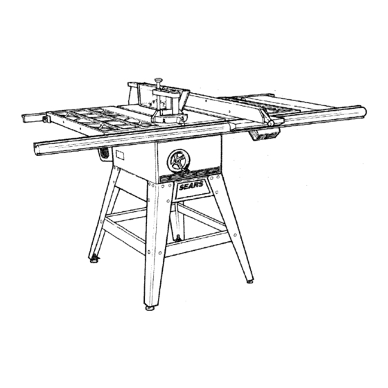
F
Save ThisManual
For Future Reference
MODEL NO.
113.299112
SAW WITH LEGS
TWO CAST IRON
TABLEEXTENSIONS
MOTOR
QUICK RELEASE
EXACT-i-RIP FENCE
SAWDUST COLLECTOR KIT
MITER GAUGE AND HOLD
DOWN
Seria!
Number
Model and serial number
may be found
at the right-
hand side of the base.
You should record
both
model and serial number
in
a safe place
for future use.
YOUR
SAFETY:
READ ALL
INSTRUCTIONS
CAREFULLY
,,...
Part No. SP5802
[RRFTZMRN
I 0" Deluxe Belt Drive Saw
• assembly
• operating
• repair parts
SEARS, ROEBUCK AND CO., Hoffman Estates, IL 60179
J
Printed
in USA
Advertisement
Table of Contents

Related Manuals for Craftsman Contractor 113.299112


Summary of Contents for Craftsman Contractor 113.299112
- Page 1 Save ThisManual For Future Reference MODEL NO. 113.299112 SAW WITH LEGS TWO CAST IRON TABLEEXTENSIONS MOTOR QUICK RELEASE EXACT-i-RIP FENCE SAWDUST COLLECTOR KIT MITER GAUGE AND HOLD DOWN [RRFTZMRN Seria! Number Model and serial number may be found at the right- hand side of the base.
-
Page 2: Safety Instructions
FULL ONE YEAR STATES and Sears will repair it, free of charge. This warranty applies only while this product is used in the United States. If lJhisTable Saw is used for commercial or rental purposes, this warranty will apply for ninety days from the date of purchase. - Page 3 R [b avoid Any power saw can throw foreign objects into the injury from jams, slips or thrown pieces (kickback and throwback): eyes. This can cause permanent eye damage. Wear safety goggies (not gtasses) that comply 1.)USE ONLY RECOMMENDED ACCESSORIES. with ANSI Z87.1 (shown on package).
- Page 4 c Wa_t for all moving parts to stop. 4. Plan way you wlll push workplece u, Check biade. Spreader a_d Fe_sce re: proper through. a_gnrnent before slar_ir_g, _._f_a n NEVER pull the workplece through. Start and 8. To avoid throwback of cut off p;e,ces: finish _e clot from the front of the table saw.
- Page 5 Addi_lona! Instructions ho_d the mi_er gauge and workp_ece ar_,d heips keep your hands away from the b!ade CROSS CUT TYPE CUTS White cutting Before starting fb avoid blade contact, aiways ho!d the miter NEVER use the rip fence wt_en crosscutting. gauge as shown in the BASIC...
-
Page 6: Requirements
MOTOR SPECIFICATIONS AND ELECTRICAL REQUIREMENTS MOTOR SPECIFICATIONS WARNING: To avoid electrical shock, do not permit fingers to touch the terminals of the This saw is designed to use a 3450 RPM motor only. Do not use any motor that runs faster than 3450 RPM. plug, when installing or removing the plug to or from the outlet. -
Page 7: Changing Motor Voltage
b. The movable links pivot on the center most WARNING: Avoid electric shock, tf the outlet screws. After links have been correctly posi- you are planning to use for this saw is of the tioned, be sure to tighten these screws to insure a two prong type, DO NOT REMOVE OR ALTER good electrical connectior_. -
Page 8: Wire Sizes
a. MOTOR tS OVERLOADED - Overioading MOTOR THERMAL OVERLOAD 0ccu[ if yet,; feed too rapidly or if sew is mis_ PROTECTOR a_igr_ecL b MOTOR C_RCL_IT IS FUSED DIFFERENTLY nr_ot--or I CAUTION: TO avoid damage, this motor FROM RECOMMENDATIONS - A!ways fotlow shoued be blown out or vacuumed frequently instructions for the proper fuseibreaker. -
Page 9: Table Of Contents
contents WARRANTY Blade Guard ............. SAFETY INSTRUCTIONS ....... Table Insert ............... FOR TABLE SAWS ......Removing and Installing Saw Blade ......41 GLOSSARY OF TERMS FOR WOODWORKIN'GI: .,.5 Exact-l-Cut ..............41 MOTOR SPECIFICATIONS AND ELECTRICAL Micro-Adjust Rip Fence ..........42 REQUIREMENTS ............ -
Page 10: List Of Loose Parts
Separate all parts from packing materials ana check each one with the illustration and the list of Loose Parts use gasoline, naptha or simiJar highly volatile to make certain all items are accounted for. before dis- j WARNING: To avoid fire or health hazard, never so,vents. - Page 11 ___d I° item Part Name Qty. Door ..............1 Saw Dust Collector ........... 1 Deflector .... Adapter Plates ..........2...
- Page 12 OF PARTS iN BAG OF LOOSE PARTS Belt Guard ............t Belt Guard Support ..........! Support Bracket ..........1 "S" Clip ..............3 Ty "TT' Pan Head Screw, 10-.32x 1/'2....2 Switc_'lAssembly ..........Hand Wheel ............2 Micro Adjust Knob Assembly ......I indicator .............
- Page 13 Spreader RodAssembly ........Guard Support ..........Drive Puley ............Grip Notch Belt112 x41........ArborWrench ............. Spreader Suppo_ ..........Bracket ............. Thumb Screw 5/!64 8x 1........ WireTie.............. BIade Guard Support S pacer ......External Lockwasher 1/4........2 Hex Nut 1/4-20 ..........2 Hex Head Screw, 5/t6-18 x 1 ......6 oc©...
-
Page 14: Assembly
ASSEMBLY Before mounting the saw on tegs or a stand or a bench, the Table _nsert and Btade Squareness must be Choked at this time. INSTALLING HANDWHEELS 1. Stide t,_e _evation bandy, heel onto its shaft. Line up ELEVATION the flat spot on the shaft with the set screw in the HANDWHEEL handv,dseol. -
Page 15: Checking Blade Squareness To Table
CHECKgNG BLADE SQUARENESS TABLE IMPORTANT; BLADE must be SQUARE (90 degrees) to TABLE, in order to proceed with MAKE SURE SQUARE assemblly. IS NOT TOUCHING TIP OF TOOTH 1. Make sure saw is off and unplugged, 2. Turn ELEVATION handwheel clockwise until blade is up as high as it will go, 3, Check for BLADE SQUARENESS..,if blade is not... -
Page 16: Mounting Saw To Leg Set
PARTS SHOWN ACTUAL S_ZE MOUNTING SAW TO LEG SET I. From a_o_g the tcx_se pa_s, find the following hard water Hex Head Screws, 5/16..18 x t-I/4" long Hex ,_quts,5/16.18 4 Lockwasher, 5/16 External Type 5/16-18 ;4 1-t/4 IN. 8 Flat Washers, !1/32 x t!/16 x 1/16 5/16-18... - Page 17 RIGHT RIGHT mNSTA.LLING TABLE SAW DUST REAR FRONT COLLECTOR NOTCH NOTCH 1. From among the loose parts, find the following hard- ware: 2 Hex Head Screw 1/4-20 x 5/8 2 Hex Nuts 1/'4-20 2 Lockwasher, t/4 External Type 2, Look underneath the saw to locate the proper posi- LEFT tion for the chute.
- Page 18 4. Thedeflector i s mounted t o the rearof thesawon theleftside viewed fromtherear.Insert t wo1/4-20 x 5/8"hexheadscrews through the outside holesof the deflector, marked "X".andthrough thebottom frameofthesawcabinet. Install I ockwasher andnut to eachscrew.Aligndeflectorwithsawcabinet. REAR "l]ghten nuts. SAW BASE CABINET 5. Connect oneendof the2-1/2" x 7' hosetothe dis- charge opening a ndtheotherendto yourCRAFTS- MAN SawDust C ollector System orWet/Dry V ac.
- Page 19 1111111111111i!11 ATTACHmNG AND ASSEMBUNG TABLE EXTENSmONS 5/16-18 X 1-1/4 IN. 5/16-18 HEX HEAD SCREW WARNING: Stock table extensions must HEX NUT installed. They hetp support the fence rail. An unsupported rail can twist. Twisted rail can mis- aiign fence. A misaligned fence can cause bind- ing or kickback.
-
Page 20: Installing Table Extension Brackets
iNSTALLiNG TABLE EXTENSION BRACKETS 1. From among the loose parts find the following hard- ware: 5/16 IN, EXTERNAL 5/16 IN. 4 Hex Head Screws. 5/16-18x 1" long 4 Lockwashers, 5/16 External Type 4 Flatwashers. 21/64" inside dia. 4 Hex Nuts, 5/16-18 4 Brackets 21/64 IN. -
Page 21: Installing Front Rip Fence Guide Bar
RNSTALLUNG FRONT RIP FENCE GUIDE 1. From among the loose parts find the following hard- 1 " SQ, HD. SCREW ware: 4 Sq. Head Screws, 5/16-18 x 1" long 2 Sq. Head Screws, 5/16-18 x 3/4" long 6 External Lockwashers, 5/16" inside diam. 6 Flat Washers, 21/64"... - Page 22 6. Holding the guide bar in place with one hand, insert a flat washer, Iockwasher and nut on each screw starting from the center and alternating left and right. =inger tighten only until all six screws nave washers. lockwashers and nuts installed. Hand tighten 4 nuts at saw table first.
-
Page 23: Installing Rear Fence Guide Bars
tNSTALU_G REAR FENCE GUIDE BAR I. From among tt_e _ooseparts find the following: 3i4" SQ, HD. SCREW 4 Sq. head screws, 5/16--18 x 1" long 2 Sq. head screws, 5/16-18 x 3/4" torT,q 6 Externat lockwashers, 5/16" I.D. 6 Flat washers, 21/64" I.D. 6 Hex nuts, 5/!6-18 1 Rear guide bar 6!"... -
Page 24: Adjusting Rip Fence Guide Bars
ADJUSTING RiP FENCE GUIDE BARS VERY THIN SHIM WASHER ,,_CREW LOCATIONS VIEW' FROM TOP OF SAW 1. From among the loose parts find the following hard- ware: 10 Very Thin Shim Washers 2. Loosen the 6 nuts holding the rear guide bar in place, Holding the guide bar against the saw table and extensions, note if there is any gap between the SCREW... -
Page 25: Installing Separator Channel
INSTALUNG SEPARATOR CHANNEL [ 11 IIIIIiD WARNING: Separator channel must be properly installed to help keep thin work from stipping beneath the fence and heBp keep the fence raits 5/16-18 X 3/4 5/16-18 X 3/4 IN. HEX HEAD SCREW SQ. HD. SCREW straight. -
Page 26: Rip Fence Alignment Adjustment
Slide assembly to the left until it is 4" from the exten- sion table. Adjust the extension table brackets against the back of the front guide bar and then fin- ger tighten the two nuts. 6. Check dimension from side of right extension to le_t side of channel at front guide bar and rear guide bar, Adjust to insure both dimensions are identical. -
Page 27: Rip Fence Lock Lever Adjustment
RiP FENCE LOCK LEVER ADJUSTMENT WARNING: Make sure the fence lock works in the center and at each end of the fence rail. An improperly adjusted fence could move. Movement could cause binding or kickback. could be hit or cut. 1. - Page 28 8. Find the "0" inch mark on the end of the 30" long O" MARK 2" MARK RED LINE right measuring tape. Slide this end of the measuring ON INDICATOR tape under the right side of the indicator and push tape along top surface of rip fence guide bar.
-
Page 29: Assembling Micro Adjust And Racks
18,Align thefence's p lastic endcaptomatch t heprofile of the head.Install2 self tap 10-32pan head screws intotheholes. NOTE:Adjust c apso it doesnot interfere withfront guidebar, The screwsare self tapping.Drivethe screws i n until c apisseated against thefence head. © ASSEMBUNG MICRO ADJUST AND RACKS ! 0-32 3/16"... - Page 30 3 instant theotherrackfromthe right e ndina similar manner asdescribed in #2.sliding rackagainst left FRONT rack. T ighten a ttscrews. GUIDE BAR 4 _ake micro-adjust assembly andinsert t wopanhead screws 10-32 x 3/8"long withlockwashers to holes mm,,cro a djust m ount. I nstall 1 0-32 square nutsto screws leaving 1/8"plusbetween inside of nutand topofmicro adjustmenL 5.
-
Page 31: Mounting Switch
MOUNTING SWITCH 1. From among the loose parts find the following hard- ware: EXISTING SWITCH ASSEMBLY 1 Switch Assembly with Bracket 2 Pan Head Screws 10-32 x 3/8" long 2 Lockwashers - 3/16" I.D, 2 Square Nuts - 10-32 3/16" 6 Pan HD ScrewTy "T"... -
Page 32: Installing Blade Guard
© © INSTALLING B_DE GUARD 1. From among the loose parts, find: HEX NUT 1/4" LOCKWASHER 5/16" LOCKWASHERS Rex Head SCrew& 1/4-20X5/8, long Hex Head Screws, 5/i6-18 x 5/8, long Hex Head Screws, 5/t6,18x 1" long Bex Nuts, 1/4_20 (approx. dia: of hole 1/4") Lockwashers;... - Page 33 Slide SPREADER ROD into BLADE GUARD SUP- PORT until end of ROD is even with edge of SUP- PORT,.,lqghten Hex Head Screw in support. Attach SPREADER to SPREADER SUPPORT so that the edge of the spreader is even with the edge SQUARE of the spreader support...tighten screws.
-
Page 34: Positioning Motor On Motor Mounting Base
17.Place RIPFENCE ontable. , , FOLDED CAREFULLY move itagainst blade sothat_t i spar- alle!to theblade, a ndjustTOUCHES t ipsof saw teeth...tighten RIPFENCE LOCK LEVER. 18.InsertfoldedpaperbetweenSPREADER AND FENCE. 19.Usinga 7/16in. wrench._oosen t he 1/4-20 hex 7/16 WRENCH head screws sothespreader canslide sideways. 20. -
Page 35: Mounting The Motor
MOUNTING THE MOTOR 1. From among the loose parts find the following hard- ware: CARRIAGE Carriage Bolts, 5/16-t8 x 3/4'! tong Hex Nuts, 5/16-18 (approx. dia. of hole 5/16") Lockwashers, 5/16 in, External Type (apprex, 5/16" HEX NUT dia. of hole 5/! 6") Cast Iron Motor Pulley 5/16"... -
Page 36: Installing Belt Guard
10.Make sure blade is90°totable., .raise it all the way 11. Lift motor until edge of washer (see illustration) is even with _nd of slot. in this position, pull motor toward you(pins will slide in the cradle) until belt is TIGHT...make sure washer is still even with end of slot...tighten the two MOTOR BASE CLAMPS SCREWS. -
Page 37: Motor Connections
6. Reinstall motor pulley the same way it was when you BELT aligned the belt. Tighten setscrew. MOTOR pULLE_"_'_ 7, Place belt on SAW PULLEY,..insert end of belt ._'_ _'_ -_ through opening in END of guard. 8, Slip belt over motor pulley, <14 9. - Page 38 2. Screw on the handle (1) received with Hold-Down. NOTE: If your Craftsman Miter Gauge has a LOCK KNOB instead of a long handle, it will be necessary to disassemble the miter gauge and install the THREAD- ED STUD and LOCK NUT suppliec with the Hold- Down.
-
Page 39: Ge'i-Fing To Know Your Saw
GETTING TO KNOW YOUR SAW SAWBLADE EXACT-I-CUT 7 BLADE GUARD 8 TABLE INSERT ANTIKICKBACK 6 MITER GAUGE PAWLS RIP FENCE RIP FENCE LOCK HANDLE 4 TILT LOCK HANDLE (UNDERNEATH 11 MICRO-ADJUST ELEVATION HANDWHEEL 3 TILT HANDWHEEL SEPARATOR 1 ON-OFF SWITCH CHANNEL 1 ON-OFF SWITCH the blade guard is correctly installed and operat-... -
Page 40: Elevation Handwheel
6 MITER GAUGE_.head is locked _nposition for ELEVATION HANDWHEEL...elevates or lowers the blade_ Turn clockwise to elevate, counterclockwise crosscut£ng or mitenng by t_ghtening the !ock knob. ALWAYS LOCK tT SECURELY WHEN IN USE. to lower. There are slots for the stop p_nat the 45 degree right NOTE: Any t_me sawblade has been etevated to 2- and tuft pos_bonsfor conveniently setting the M_ter... -
Page 41: Removing And Installing Saw Blade
NEVER OP_]RA]E THE S,_¢d WiT_-iOUT ii-iE PROP- ER INS_:!R,T iN PLAC! USE! TRE BLAOE NSERT WHEN SAWING. T?_._:: C QMBiNATiOt,_ DA©O MOLDING iNS_!:RT WHEN DADOING MOLD NG BLADE GUARD NOT SHOWN FOR PICTURE CLARITY RElieVE AND _NSTALUNG SAWBLADE. start, turn ._}witch 'OFF"... -
Page 42: Micro-Adjust Rip Fence
11 MICRO-ADJUST RiP FENCE, .,atlows the opera_or to accurately aajust the rip fence using onw one hand. To move the fence, push in _n the micro- adjust knob and rotate the knob. Rotai_ng the knob c!ockwise moves the fence to the left Rotating it counterclockwise moves the fence to the rig_t. -
Page 43: Push Stick And Push Block
3/4" PLYWOOD WORK FEEDDKV{CKS (cor_tinued) Making the hand!e: C ..o_'o8 ir_ch thick n, ,,I _ piece ply",tvooc_ t o shape and " _ SIqOWR: NOTE: The mitered corners ea_sbe any s_=ze that looks o Position! the hande in the cef_ter of tf-_e #tywood base. -
Page 44: Safety Instructions For Basic Saw Operations
SAFETY INSTRUCTIONS FOR BASIC SAW OPERATIONS BEFORE EACH USE: 4 Choose and inspect your cutting tool carefully. To avoid cutting too! failure and thrown 1. Inspect your saw. shrapnel (broken pieces of blade), use only 10" or smatler blades or other cutting tools To avoid injury from aCCidenta_ starting, unptug marked for speeds of 3450 rpm or higher. - Page 45 3. Inspect your workpiece. Make sure there are no nails P_an ahead to protect your eyes, hands_ face, ears, or foreign objects in the part of the workpiece to be cdt- a To avoid injury from accidentai b!ade contact, doHt do iayout, assembly, or setup work ors the 4.
- Page 46 Make sure the, _ [co _f the ardor or cutting tool turns Plan the way you will push the workpiece through. toward [ne front ot the sa'v', NEVER pull the workpiece through. Start and finish the cut from the front of the table saw. Set ;no cutting [oo_ as tow as possible for the cut...
-
Page 47: Using The Miter Gauge
An auxiliary wood facing attached to the miter USING THE M_TER GAUGE gauge can help prevent workpiece twisting and THE _IiTER GAUGE _8 USED WHEN CROSSOUT- throwbacks.Attach it to the holes provided. Make the facing long enough and big enough to support TING, MITER CUTT!NG, BEVEL CUTTING, COM-... -
Page 48: Repetitive Cutting
Whencuttinglong workpieces, invertAUXILLIARY FENCEZWQRK SUPPORT andposition itontopofthe guidebarstosupport theworkp_eces asnear t otheend aspossible, i f t!_isdoesnotadequately s upport t he workpiece, youcanmakea simple s upport byclamping a piece ofplywood t oasawhorse. Usethe hold-downclampon the mitergaugefor greater accuracy: REPETITIVE CUTTING REPETITIVE CUFFING is known as cutting a quantity of pieces the same length without having to mark each piece, 1 Use the Stop Rods (optional accessory) only for cut-... -
Page 49: Miter Cutting
1.NEVERUSETHERIP FENCEASA LENGTH STOPBECAUSE THECUTOFF PIECECOULD BINDBETWEEN THEFENCE ANDTHEBIJkDE CAUSING A KICKBACK. 2.Whenmaking r epetitive c utsshorter than6",clamp a blockofwood2"longtothetabletoactasa length BLOCK stop,Donotclamp directly t othebottom edge ofthe tablebecause t he"swivel" o ftheclamp wit!notgrip properly. Place a smal!blockof woodbetween t he bottom edge ofthetableandthe"C"clamp. -
Page 50: Using The Rip Fence
USING THE RiP FENCE A FEATHERBOARD can help guide the work- p_ece RIPPING. BEVEL RIPPING PLOUGHING. MOLDING RESAWlNG AND RABBETING are performed using RIP FENCE together With the AUXILIARY 5/16" APART FENCE/MJORK SUPPORT, PUSH STICK OR PUSH KERFS ABOU1 1---_ BLOCK. -
Page 51: Using Featherboards For Thru-Sawing
USING FEATHERBOARDS THRU-SAW_NG ¢ "C"CLAMPS FEATHERBOARD Featherboards are not employed for thru sawing oper- FEATHERBOARD ations when using the miter gauge, "C"CLAMPS WORK SUPPORT Featherboards are used to keep the Work in contact with the fence and table as shown, to help st(_;p kickbacks. - Page 52 When "WIDTH OF RIP" is 2 tn. or wiaer LJSE THE PUSH STICK to finish pushing the work a_ the way past the blade. When WIDTH OF RIP is 1/2" to 2 in., tlqe pusn st_ct< CANNOT be used because the guard will interfere USE the AUXILIARY FENCE/WORK SUPPORf...
-
Page 53: Resawing
Narrow stripsthickerthanthe AuxiliaryFence/Work Supportmay enterthe guardandstrike the baffle. BAFFLE CAREFULLY t'aiseguardonly enoughto clea_the workpiece UsePUSH BLOCK tocomplete c ut. WARNING: To avoid #;iury from b_ade contact, never thru saw rip cuts narrower than t/2" wide. RESAWJNG < RESAWING is known as ripping a piece of wood through its thickness. -
Page 54: Using Featherboards For Non-Thru Sawing
USING FEATHERBOARDS NON THRU-SAWING "c" CLAMPS Featherboaras are not employed during non tr_ru-saw- FEATHERBOARD ing operations when using the miter gauge. WORK SUPPORT Use featherboards for all other non "thru-sawing" operations [when sawblade guard must be removedk Featherboards are used to keep the work in contact with the fence and table as shown, ana to stop kick- backs. -
Page 55: Rabbeting
RABBETING RABBETING is known as cutting out a section of the corner of a piece of material, across an end or along an FIRST CUT edge. RABBET To make a RABBET requires cuts which do not go all the way through the material. Therefore the blade guard must be removed. -
Page 56: Dadoing
DADOING Instructions for operating the Dado Head are contained © in a booklet furnished with the Dado Head. The arbor on the saw, is only long enough so that the widest cut that can be made is 13/16" wide. It is not necessary to install the outside loose collar before screwing on arbor nut. -
Page 57: Adjustments
ADJUSTMENTS WARNING: For your own safety, turn switch ] "OFF" and remove pUug from Power source out- _etbefore making any adjustments, MITER GAUGE NOTE: The holes for the stop pin and the graduations CLAMP LOCK "_ are manufactured to very close tolerances which pro- "="4 vide accuracy for average Woodworking. - Page 58 P_ace the head of a com_r_at_on square _n the GROOVE ad_us_ blade of sqL_are so treat _I jus! toucl_es t_e _D of lb,e MARKED top,n, Move sq{_are to REAR rotate blade to see if MARKED tooth ag;_n toucr}es [:_ade of square. 5.
-
Page 59: Blade Tilt, Or Squareness Of Blade To Table
BLADE T_LT, OR SQUARENESS OF BLADE TO TABLE WT,:>t _Te bevel ponte is !,oi _t n9 directly to the '0' rra:k (_ _e, ,_,_,,, scae. the sawMade st ou_d make a • ,,0 t _,, e_., to the taHe 90' POSiTiON ;% c qec <for SQUARENESS: [-6_G7 For your... -
Page 60: Degree Position
tf b_ade i s NOTSQUARE t otabIe.,,the 9 0degree s top screw must b eADJUSTED A. Unscrew 90 degree STOP SCREW three to four _ums usil_g 3/16 tn HEX L" wrench. B -rum tilt handwheet ciockwise one turn taen turn handwnee_ counterc½ockwise u_tit blade _s square w_tt_table... -
Page 61: Tilt Mechanism
Frequently clean your curing tools with Craftsman Gum and Pitch Remover. t. Remove b!ade guard. A coat of furniture type wax app!ied to the table wilt hetp... -
Page 62: Lubrication
Tilt screw threads and pivot nut, (First Clean with Craftsman Gum & Pitch Remover). Elevation screw tiqreads and pivot nut (First Clean with Craftsman Gum & Pitch Remover), 3, Cradle bearing points. 4. Bearing points in guard assembly, m_ter gauge and rip fence. -
Page 63: Troubleshooting
TROUBLESHOOTmNG WARN!NG: To avoid injury turn switch "OFF" and always remove plug from power source outlet before I troubleshooting, TROUBLESHOOTING - GENERAL TROUBLE PROBABLE CAUSE REMEDY Excessive vibration. Blade out of balance, 1, Discard Blade and use a different blade, .......... -
Page 64: Motor
TROUBLE SHOOT_NG = P_OTOR {Continued) PROBABLE CAUSE REMEDY TROUBLE 1. Low voltage will not Motor starts slowly !. Reques_ volt%}echeck ?ro,m the power or fails _o come up trip starting sw_tcn. compai _. to fun_speed. 2. Windings burned ouT. 2 Have motet repasted or rep,sceC. or open. - Page 65 NOTES...
-
Page 66: Repai R Parts
PARTS LIST FOR CRAFTSMAN 10 INCH TABLE SAW MODEL NO. 113.299112 FIGURE 1... - Page 67 PARTS LIST FOR CRAFTSMAN 10 aNCH TABLE SAW MODEL NO. 113o299112 Always order by Part Number -- Not by Key Number FIGURE 1 - PARTS LIST Part Part Description Description 823523 Channel, Separator Cap, Front Guide Bar End; Left I 822142 818314 Tape, Fence, Left 24"...
- Page 68 PARR lIST FOR CRAFTSMAN 10 INCH TABLE SAW MODEL NO. 113.299112 I ° 39 38 37 36 36 35 34 FIGUflE 2...
- Page 69 PARTS LiST FOR CRA| ._AN 10 INCH TABLE SAW MODEL NO, 113.299112 Always order by Part Number -- Not by Key Number FIGURE 2 - PARTS LiST Part Part Description Description 1 1625 7 STD581062 Support, Spreader * Ring, Retaining 5/8 Screw.
- Page 70 PARTS LIST FOR CRAFTSMAN 10 iNCH TABLE SAW MODEL NO. 113.299112 FIGURE 3 - RIP FENCE ASSEMBLY Key] Part Part Description Description No. i STD551210 * Lockwasher, Extemat #10 822167 Channel, Fence STD511103 * Screw, Pan Hd. 10-32 x 3/8"...
- Page 71 PARTS LaST FOR CRAFTSMAN 10 INCH TABLE SAW MODEL NO. 113.299112 FIGURE 4 = MITER GAUGE/HOLD DOWN ASSEMBLY 62776 Description Description Rod, Support 37857 62776 t Gauge/Hold Down Assembly, Handle, Miter Gauge 37897 Miter * Washer, 21/64 x I x 1/16...
- Page 72 PARTS LIST FOR CRAFTSMAN 10 iNCH TABLE SAW MODEL NO. 113.299112 FIGURE 5 - GUARD ASSEMBLY F_GURE 6 - ON/OFF POWER OUTLET Part Key i Part Description Description No. l = ,_ ..62466 60208 Nut, Push Bracket, Housing STD511103 * Screw.
- Page 73 PARTS LIST FOR CRAFTSMAN 10 iNCH TABLE SAW MODEL NO. 113,299112 FIGURE 7 - LEGS I Key I Part No. !1 Description 1805589-5 Screw, Serrated Truss Hd. 1/4-20 x 1/2 I 8_9441 _ 62554 Stiffener, Side Upper / STD551225 * Lockwasher, Ext.
- Page 74 PARTS LIST FOR CRAFTSMAN 10 gNCH TABLE SAW MODEL NO. 113o299112 FRONT GUIDE BAR (REF) SAW TABLE CREF_ FIGURE 9 -TABLE EXTENSIONS Part Description 9-22261 1" Extension, Table 12 x 27 STD541231 * Nut, Hex 5/16-18 * L0ckwasher, External 5/16...
- Page 75 PARTS LiST FOR CRAFTSMAN 10 INCH TABLE SAW MODEL NO. 113.299112 FIGURE 10 TABLE SAW DUST COLLECTOR ASSEMBLY Part Description Chute, Collector 821386 Door, Collector 821384 Adapter 2-.1/2"Hose 9--17820 821383 Rear Deflector 821387 NOTE: Key No. "4" is available through your iocal Sears...
- Page 76 For the repair or replacement parts you need Call 7 am - 7 pro, 7 days a week 1-800-366-PART (1-800-366-7278) For in-home major brand repair service TO ORDER Gall 24 hours a day, 7 days a week t -800-4-REPAIR REPAIR PARTS (1-800-473-7247) The Model Number Of Your Table Saw Is Found AtThe Right Hand...