Table of Contents
Advertisement
Advertisement
Table of Contents

Related Manuals for Craftsman 917.255732


Summary of Contents for Craftsman 917.255732
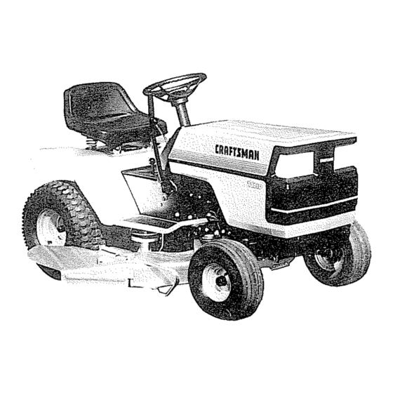
- Page 1 SEA/ S OWNERS MANUAL MODE L NO. 917.255732 11 H,P, Caution: 38" RIDJNG Read Rules for Safe Operation LAWN TRAC TOR and Instructions Carefully ELECTRIC START Assembly Installation Operation Repair Parts ..ii u l Sears, Roebuck and Co., Chicago, IL 60684 US.Ao t"...
-
Page 2: Warranty
CONGRATULATIONS your purchase of a Sears Lawn Tractor, It has been designed, engineered and manufactured MODEL to give you the best possib{e dependability and performance NUMBER ..;_ ..:;,_. _ ..,-._ .._. Should experience any problem cannot easily reme- SERIAL... - Page 3 RULES FOR SAFE OPERATDON WARNING: This unit is equipped with an internal combustion engine and should not be used on or near any unimproved forest- covered, brush-covered or grass-covered land unless the engine's exhaust system is equipped with a spark arrester meeting applicable local or state laws (if any)
- Page 4 ASSEMBLY To assemble your Tractor you will need: two 7/16" wrenches, two 9/16" wrenches, and a 3/4" 1v Remove Shipping Strap Banding, Battery, Steering Wheel wrench and Bag of Parts (under Hood). NOTE: RIGHT HAND (R.H.) AND LEFT HAND (LH°) ARE 2.
- Page 5 2. Position Battery in tractor as follows: a. Lift Seat Pan so it rests on Steering Wheel (Fig° 3)o b, Lower Battery into Fender Wel! with Battery Terminals toward front of tractor° Make sure Battery rests in Bat- ¸ tery Tray (Fig.
-
Page 6: Seat Installation
INITIIAL ADJUSTMENTS 1. SEAT INSTALLATION a,. Place Seat on Seat Pan.. Screw Adjustment Bolt, Lock_ washer and Fiat Washer into Seat° Adjustment Bolt, Lockwasher and Flat Washer"found in Bag of Parts= Tighten finger tight. CLUTCHIBRAKE bo Place Seat in operating position. Sit on the Seat and 'MENT PEDAL press Crutch-Brake Pedal all the way down. - Page 7 INITIAL SERVRCE NOTE: BE CAREFUL NOT TO ALLOW DIRT TO ENTER ENGINE WHEN CHECKING OR ADDING FUEL Io Pull up at rear of Hood to open, 2 Check Engine Oil Level with Tractor on level ground, Re- move and wipe Dipstick (Fig. 9) cteano screw it in tight for a few seconds, remove and read Oil Level°...
-
Page 8: Operation
CAUTION Keep all shields in place_ Before leaving operator'Jsposition: a., Shift lever to neutral (Fig,, 10),. b. Depress Clutch/Brake Pedal and set Parking Brake (Fig. 10)_ c_ Disengage attachment clutch (Mower Blade Clutch Lever) (Fig. 10),_ d. Shut off engine, eo Remove ignition key= MOWERBLADE CLUTCH"ENGAGED"... -
Page 9: Mower Adjustment
MOWER nNSTALLATION CLUTCH PARAI. LE L RETAINER RETAINER LINK FRONT SPRINGS Your 38" Mower installs without the use of toots,, Raise Lift SPRING AXLE Lever (Fig° 1t) to its highest position. Turn Depth Adjust- CLUTCH ment Knob to towest positign (Fig, 14L 1. -
Page 10: Side To Side
LEVEL MOWER FROM SIDE TO SiDE LIFT SEE MOWER ADJUSTMENT, PAGE 9_ PLUNGER 1, Park tractor on level sur_face.,Depress Lift Lever Plunger L I FT and use Lift Lever to raise mower to maximum cutting LEVER height, SIDE-TO*SiDE /IENT Measure height of Top of Flange to tevel surface at front of mower°... - Page 11 OPERATRON = MOWER MOWER CLUTCH LEVER '*DISENGAGED" POSITION READ THE "RULES FOR SAFE OPERA- MOWER CLUTCH LEVER DEPTH TION" CAREFULLY BEFORE OPERAT- "ENGAGED" POSITION ADJUSTMENT ING YOUR MOWER, KNOB LIFT LEVER LIFT MOWER MUST BE ADJUSTED PROPERLY FROM LEVER FRONT TO REAR AND LEVELED FROM SIDE TO SIDE...
-
Page 12: Maintenance
When grinding, care should be taken to maintain blade bal- ance and the blade should be checked for proper balance before reinstallation on mower,. Unbalanced or bent blade will cause excessive vibration when running, and eventual damage to mower or engine. Replace bent, damaged or un- balanced blades. - Page 13 TRACTOR OPERATmON LEVER PLUNGER 1. Depress Lift Lever Plunger at top of Mower Lift Lever and _...,_,..,__ MOWER LIFT LEVER move Lever rearward to its _HIGHEST" position (Fig. _'°HIGHEST" POSITION 23). 2, With engine running and warm, place Throttle Control ÷...
-
Page 14: Daily Maintenance
ST,ART NG YOUR TRACTOR WaTH MAtNTENANC E -=YRAC YOR A LOW 6ATTERY MOWER MAINTENANCE IS LISTED ON PAGE If your Battery is too low to start the engine, it should keep your tractor running better, longer; perform neces- • tt recharged. - Page 15 4,, CHECK BRAKE OPERATION This tractor is equipped with an adjustable disc brake mounted on the right side of the transaxle (Fig, 27). DISC BRAKE IF TRACTOR REQUIRES MORE THAN FEET STOPPING DISTANCE HIGHEST GEAR, THEN BRAKE MUST BE ADJUSTED. BRAKE NOTE: WHEN...
- Page 16 Ev .vB@ .ouns INTAKE 1, CLEAN ENGINE COOLING FINS Keep Engine Cooling Fins free of dust, dirt and oil to pre- vent Engine damage from overheating. a. Pull up to remove !ntake Air Duct (Fig, 29). b_ Remove four Bolts from blower housing,, c.
- Page 17 Ew.v IDLE MIXTURE THROTTLE IDLE SCREW CABLE, REPLACE CLEANER ELEMENT STOP DO NOT ADJUST HOLES "A" CARBURETOR ADJUSTMENT (FIGo 31) Never attempt to change maximum engine speed, This is preset at the factory and should only be changed by a quali- fied service technician who has the necessary equipment.
- Page 18 REPLACE TRACTOR MOTION DRIVE BELT BELT 5 ,, GUIDE The tractor Drive Belt may be reptaced without tools.. Park tractor level area. Engage Parking Brake, NOTE: TRANSAXLE PULLEY BELT INSTALLATION DECAL UNDER LEFT FOOT- REST. a. Remove mower. (See Mower Section, page 20).
- Page 19 7, TIRE CARE a, Maintain tire pressure in front tires at 14 PS! and rear tires at 12 PSI, KLIP RING Keep tires free of gasoline, oil, or insect control chemi- cals which can destroy rubber c, Avoid stumps, stones, deep ruts and other hazards...
- Page 20 TO REMOVE MOWER BELT MOWER CLUTCH LEVER "'DISENGAGED" NOTE: MOWER BELT INSTALLATION DECAL LOCATED POSITION ON MOWER HOUSING. "'HIGHEST" ITION REPLACE ONLY WITH BELTS SPECIFIED IN THIS DEPTH ADJUSTME NT MANUAL, KNOB Place Mower Blade Clutch Lever in _DISENGAGED LIFT LEVER position (Fig 37) "LOWEST"...
- Page 21 TROU,LESNOOT,NG POSSIBLE REMEDY POSSIBLE CAUSE WILL NOT START Place in neutrai Shift Lever in gear Mower Blade CIutch Lever engaged Disengage Lever (Fig. 10). Be sure Lever is in bottom of slot Fi{I Tank with Gasoline Check Fuel Line and Car- No gasoline in Fuel Tank, clogged...
-
Page 22: Lubrication Chart
LUBRICATIONCHART AXLE PIVOT SPINDLE FRONT WHEEL BEARING FRONT WHEEL BEARING (_TIE CLUTCH PIVOT LUTCH/BRAKE PIVOT /BRAKE PIVOT ATTACHM LIFT HMENT LIFT ARM 1_) MOWER CLUTCH PIVOT (_SAE 30 MOTOR GENERAL PURPOSE GREASE SERVICE RIECOgB FILL IN DATES SERVICE DATES AS YOU COMPLETE REGULAR SERVICE Check... - Page 23 11 H°P, 38" RIDING LAWN TRACTOR--MODEL NUMBER 917,255732 SCHEMATIC oltllo BLACK STARTER NEUTRAL ATTACH WHITE--_C_ WHITE Of---'---_tNTER'K ,NTER'K SOLENOID% BLACK IGNITION IGNITION SWITCH '" MAGNETRON SPAR K PLUG 30 AMP BLACK ..IGNITION SWITCH _[_/ RECTIFIER CHARGING STD365402 IRED..POSITION CIRCUIT (DIODE) COIL...
- Page 24 REPAIR PARTS 11 H.P. 38" RIDING LAWN TRACTOR--MODEL NUMBER 917.255732 ELECTR ICAL...
- Page 25 REPAIIR PARTS 11 H.P. 38" RIDING LAWN TRACTOR--MODEL NUMBER 917.255732 ELECTRICAL PART DESCRIPTION PART DESCRIPTION 719J Cover, Terminal 7662J Bulb, LIght 5114J Cable, Battery 105386X Harness, Light Socket 105737X Switch, Interlock !06480X Harness, tgmtIon 2033J Cable, Battery STD365410 Key Set STD522507 *Bolt, Hex, 1/4- 20 x 3/4...
- Page 26 REPA|R PARTS 1! H.P. 38"' RIDING LAWN TRACTOR--MODEL NUMBER 917.255732 ENCLOSURE...
- Page 27 Screw, Hex Washer Thd. Roll 3/8 t05802X Decal, Stripe, L.H. t6 x 1/2 105803X Decal. Stripe, R.H.. ",4 105753x Bracket, Fender t05806X Decal, Grill Craftsman 105465X Footrest, L.H. t05807X Decal, Grill, Strtpe 105464X Footrest, R.H, 4900J Decal, Clutch/Brake STD533707 *Bolt.
- Page 28 REPAIR P, TS 1t H.P. 38" RIDING LAWN TRACTOR--MODEL NUMBER 917.255732 DRIVE OPTIONAL EQUIPMENT Spark Arrester Screen Assembly 677Vl - 28-...
- Page 29 REPAaR PARTS 11 H.P. 38" RIDING LAWN TRACTOR--MODEL NUMBER 917.255732 DRIVE PART DESCRIPTION PART DESCRIPTION I01325N 19131312 Washer 13/32 x 13)'16 x 12 Ga, Engine, 11 H.P. Model No. 252707, Type Noo 0669-01 105730X Keeper, Belt, Engine 105731X Putley, Engine 106191X Keeper, Belt 9767H...
-
Page 30: Lawn Tractor-Model
RE_IR PARTS 11 H.P. 38" RIDING LAWN TRACTOR-MODEL NUMBER 917.255732 STEERING AND FRONT AXLE 56 57 - 30 -... - Page 31 REPAnR PARTS 11 H.P. 38" RIDING LAWN TRACTOR--MODEL NUMBER 917.255732 STEERING FRONT AXLE PART DESCRIPTION PART DESCRIPTION 105620X Dash 19212016 Washer 21/32 x 1- 1/4 x 16 Ga, 74180512 Screw- Truss Hd. Cross Recess 105641X Shaft - Steering _ Lower 5/16 - 18 x 3/4 2882J Pin - Drive 3/16 x 1...
- Page 32 REPAmR PARTS 11 H.P. 38" RIDING LAWN TRACTOR-MODEL NUMBER 917.255732 LI FT ADJUSTM 29 30 - 32 -...
- Page 33 REPA ilR PARTS 11 H.P. 38" RIDING LAWN TRACTOR--MODEL NUMBER 917.255732 LI FT ADJUSTM PART DESCRIPTION PART DESCRIPTION 106448X Lever, Clutch, Mower 2876H Spring 9439M Knob 19131016 Washer 13/32 x 5/8 x 16 Ga. I06451X Bolt, Shoulder 10!272K Trunnion, Depth Adjustment 73680600 Nut, Lock, 3/8 - 16 19151216...
- Page 34 REPAtR PARTS 11 H.P, 38" RIDING LAWN TRACTOR--MODEL NUMBER 917.255732 38" MOWER ± _ 34 -...
- Page 35 KPAUR PARTS 11 H.P. 38" RIDING LAWN TRACTOR--MODEL NUMBER 917.255732 38" MOWER DESCRIPTION PART DESCRIPTION PART V-Belt 106634X Blade, 38" 106085X 19132012 Washer 13/32 x 1 - 1/4 x 12 Ga. 105689X Housing STD551137 *Washer, Lock, 3/8" Runner, R .H.. 8417J STD632715 *Boit, Hex, 3/8 - 24 x 1 - 1/2 Gr_,5...
-
Page 36: Repair Parts
REPAIR PARTS 11 H.P. 38"' RIDING LAWN TRACTOR_MODEL NUMBER 917.255732 - 36 -... - Page 37 REPAUR PARTS 11 H.P° 38" RIDING LAWN TRACTOR--MODEL NUMBER 917.25,5732 PART DESCRIPTION PART DESCRIPTION 105903X Housing, Upper 105928X Sprocket, 9T, Reverse Drive 2276J 2285J Screw, Tapping, !/4 - 20 x 1.31 Lg Bolt, Shoulder " 2274J 105930X Screw, Tapping, 1/4 - 20 x °875 Lg. Washer, Plain, °758 x 1_12 x .0t5 68003 Ball, Detent...
- Page 38 mEpAem PAINTS 11 H.P. 38" RIDING LAWN TRACTOR-_MODEL NUMBER 917.255732 ENGINE+-MODEL NUMBER 252707, TYPE NUMBER 0669+01 CYLINDER BLOCK GROUP ' 105 GASKET - 38 -...
- Page 39 REPAmR PARTS 11 H.P. 38" RIDING LAWN TRACTOR--MODEL NUMBER 917.255732 ENGINE--MODEL NUMBER 252707, TYPE NUMBER 0669_01 CYLINDER BLOCK GROUP PART DESCRIPTION PART DESCRIPTION Breather Assembly 93158 Screw _Blower Hsg Mtg., Sem 391406 Screw- Sere 391556 Housing- Btower 93394 Key - Flywheel 19203 Puller- Flywheel 222698...
- Page 40 REPAmR PART6 11 H.P. 38" RIDING LAWN TRACTOR_-MODEL NUMBER 917.255732 ENGINE-MODEL NUMBER 252707, TYPE NUMBER 0669-01 CARBURETOR 40 -...
- Page 41 REPAnR PARTS 11 H.P. 38" RIDING LAWN TRACTOR--MODEL NUMBER 917_255732 ENGINE--MODEL NUMBER 252707, TYPE NUMBER 0669-01 CARBURETOR PART DESCRIPTION PART DESCRIPTION 93323 Screw- Air Cleaner 230896 +Pin - Float Hinge 280118 Support- Air Cleaner Element 391787 Body Assembly Carburetor (Inc. 391786 Cleaner Assembly .-Air (Inc Key Key No.
-
Page 42: Starter Motor
REPAIR PA TS 11 H.P. 38" RIDING LAWN TRACTOR--MODEL NUMBER 917.255732 ENGINE--MODEL NUMBER 252707, TYPE NUMBER 0669-01 STARTER-MOTOR PART DESCRIPTION PART DESCRIPTION 394805 Motor- Starting (Inc. Key No'so 2, 3, 391135 Clutch Assembly 4, 5,6,7, 8,9, 10, 11 & t2) 393825 Housing Assembly 94003... - Page 43 SUGGESTED GUIDE FOR SmGHTING SLOPES FOR SAFE OPERATION ONLY RIDE UP AND DOWN HILL ACROSS HiLL SIGHTING GUIDE SIGHT AND HOLD THIS LEVEL WiTH SKY LINE OR TREE Operate your Tractor up and down the face of slopes (not greater than !5°);...
-
Page 44: How To Order Repair Parts
11 H oPo SEA/RS OWNERS 38" RIDING MANUAL LAWN TRAC ELECTRIC START MODEL The Model Number will be found on the Model Plate attached Drawbar. Always mention the Model Number when 917.255732 requesting service or parts for' your Lawn Tractor. All parts listed herein may be ordered from any Sears Service Center/Departments and most Sears Retail Stores,... - Page 45 SEA/ S OWNERS MANUAL MODE L NO. 917.255732 11 H,P, Caution: 38" RIDJNG Read Rules for Safe Operation LAWN TRAC TOR and Instructions Carefully ELECTRIC START Assembly Installation Operation Repair Parts ..ii u l Sears, Roebuck and Co., Chicago, IL 60684 US.Ao t"...
-
Page 46: Warranty
CONGRATULATIONS your purchase of a Sears Lawn Tractor, It has been designed, engineered and manufactured MODEL to give you the best possib{e dependability and performance NUMBER ..;_ ..:;,_. _ ..,-._ .._. Should experience any problem cannot easily reme- SERIAL... - Page 47 RULES FOR SAFE OPERATDON WARNING: This unit is equipped with an internal combustion engine and should not be used on or near any unimproved forest- covered, brush-covered or grass-covered land unless the engine's exhaust system is equipped with a spark arrester meeting applicable local or state laws (if any)
- Page 48 ASSEMBLY To assemble your Tractor you will need: two 7/16" wrenches, two 9/16" wrenches, and a 3/4" 1v Remove Shipping Strap Banding, Battery, Steering Wheel wrench and Bag of Parts (under Hood). NOTE: RIGHT HAND (R.H.) AND LEFT HAND (LH°) ARE 2.
- Page 49 2. Position Battery in tractor as follows: a. Lift Seat Pan so it rests on Steering Wheel (Fig° 3)o b, Lower Battery into Fender Wel! with Battery Terminals toward front of tractor° Make sure Battery rests in Bat- ¸ tery Tray (Fig.
-
Page 50: Seat Installation
INITIIAL ADJUSTMENTS 1. SEAT INSTALLATION a,. Place Seat on Seat Pan.. Screw Adjustment Bolt, Lock_ washer and Fiat Washer into Seat° Adjustment Bolt, Lockwasher and Flat Washer"found in Bag of Parts= Tighten finger tight. CLUTCHIBRAKE bo Place Seat in operating position. Sit on the Seat and 'MENT PEDAL press Crutch-Brake Pedal all the way down. - Page 51 INITIAL SERVRCE NOTE: BE CAREFUL NOT TO ALLOW DIRT TO ENTER ENGINE WHEN CHECKING OR ADDING FUEL Io Pull up at rear of Hood to open, 2 Check Engine Oil Level with Tractor on level ground, Re- move and wipe Dipstick (Fig. 9) cteano screw it in tight for a few seconds, remove and read Oil Level°...
-
Page 52: Operation
CAUTION Keep all shields in place_ Before leaving operator'Jsposition: a., Shift lever to neutral (Fig,, 10),. b. Depress Clutch/Brake Pedal and set Parking Brake (Fig. 10)_ c_ Disengage attachment clutch (Mower Blade Clutch Lever) (Fig. 10),_ d. Shut off engine, eo Remove ignition key= MOWERBLADE CLUTCH"ENGAGED"... -
Page 53: Mower Adjustment
MOWER nNSTALLATION CLUTCH PARAI. LE L RETAINER RETAINER LINK FRONT SPRINGS Your 38" Mower installs without the use of toots,, Raise Lift SPRING AXLE Lever (Fig° 1t) to its highest position. Turn Depth Adjust- CLUTCH ment Knob to towest positign (Fig, 14L 1. -
Page 54: Side To Side
LEVEL MOWER FROM SIDE TO SiDE LIFT SEE MOWER ADJUSTMENT, PAGE 9_ PLUNGER 1, Park tractor on level sur_face.,Depress Lift Lever Plunger L I FT and use Lift Lever to raise mower to maximum cutting LEVER height, SIDE-TO*SiDE /IENT Measure height of Top of Flange to tevel surface at front of mower°... - Page 55 OPERATRON = MOWER MOWER CLUTCH LEVER '*DISENGAGED" POSITION READ THE "RULES FOR SAFE OPERA- MOWER CLUTCH LEVER DEPTH TION" CAREFULLY BEFORE OPERAT- "ENGAGED" POSITION ADJUSTMENT ING YOUR MOWER, KNOB LIFT LEVER LIFT MOWER MUST BE ADJUSTED PROPERLY FROM LEVER FRONT TO REAR AND LEVELED FROM SIDE TO SIDE...
-
Page 56: Maintenance
When grinding, care should be taken to maintain blade bal- ance and the blade should be checked for proper balance before reinstallation on mower,. Unbalanced or bent blade will cause excessive vibration when running, and eventual damage to mower or engine. Replace bent, damaged or un- balanced blades. - Page 57 TRACTOR OPERATmON LEVER PLUNGER 1. Depress Lift Lever Plunger at top of Mower Lift Lever and _...,_,..,__ MOWER LIFT LEVER move Lever rearward to its _HIGHEST" position (Fig. _'°HIGHEST" POSITION 23). 2, With engine running and warm, place Throttle Control ÷...
-
Page 58: Daily Maintenance
ST,ART NG YOUR TRACTOR WaTH MAtNTENANC E -=YRAC YOR A LOW 6ATTERY MOWER MAINTENANCE IS LISTED ON PAGE If your Battery is too low to start the engine, it should keep your tractor running better, longer; perform neces- • tt recharged. - Page 59 4,, CHECK BRAKE OPERATION This tractor is equipped with an adjustable disc brake mounted on the right side of the transaxle (Fig, 27). DISC BRAKE IF TRACTOR REQUIRES MORE THAN FEET STOPPING DISTANCE HIGHEST GEAR, THEN BRAKE MUST BE ADJUSTED. BRAKE NOTE: WHEN...
- Page 60 Ev .vB@ .ouns INTAKE 1, CLEAN ENGINE COOLING FINS Keep Engine Cooling Fins free of dust, dirt and oil to pre- vent Engine damage from overheating. a. Pull up to remove !ntake Air Duct (Fig, 29). b_ Remove four Bolts from blower housing,, c.
- Page 61 Ew.v IDLE MIXTURE THROTTLE IDLE SCREW CABLE, REPLACE CLEANER ELEMENT STOP DO NOT ADJUST HOLES "A" CARBURETOR ADJUSTMENT (FIGo 31) Never attempt to change maximum engine speed, This is preset at the factory and should only be changed by a quali- fied service technician who has the necessary equipment.
- Page 62 REPLACE TRACTOR MOTION DRIVE BELT BELT 5 ,, GUIDE The tractor Drive Belt may be reptaced without tools.. Park tractor level area. Engage Parking Brake, NOTE: TRANSAXLE PULLEY BELT INSTALLATION DECAL UNDER LEFT FOOT- REST. a. Remove mower. (See Mower Section, page 20).
- Page 63 7, TIRE CARE a, Maintain tire pressure in front tires at 14 PS! and rear tires at 12 PSI, KLIP RING Keep tires free of gasoline, oil, or insect control chemi- cals which can destroy rubber c, Avoid stumps, stones, deep ruts and other hazards...
- Page 64 TO REMOVE MOWER BELT MOWER CLUTCH LEVER "'DISENGAGED" NOTE: MOWER BELT INSTALLATION DECAL LOCATED POSITION ON MOWER HOUSING. "'HIGHEST" ITION REPLACE ONLY WITH BELTS SPECIFIED IN THIS DEPTH ADJUSTME NT MANUAL, KNOB Place Mower Blade Clutch Lever in _DISENGAGED LIFT LEVER position (Fig 37) "LOWEST"...
- Page 65 TROU,LESNOOT,NG POSSIBLE REMEDY POSSIBLE CAUSE WILL NOT START Place in neutrai Shift Lever in gear Mower Blade CIutch Lever engaged Disengage Lever (Fig. 10). Be sure Lever is in bottom of slot Fi{I Tank with Gasoline Check Fuel Line and Car- No gasoline in Fuel Tank, clogged...
-
Page 66: Lubrication Chart
LUBRICATIONCHART AXLE PIVOT SPINDLE FRONT WHEEL BEARING FRONT WHEEL BEARING (_TIE CLUTCH PIVOT LUTCH/BRAKE PIVOT /BRAKE PIVOT ATTACHM LIFT HMENT LIFT ARM 1_) MOWER CLUTCH PIVOT (_SAE 30 MOTOR GENERAL PURPOSE GREASE SERVICE RIECOgB FILL IN DATES SERVICE DATES AS YOU COMPLETE REGULAR SERVICE Check... - Page 67 11 H°P, 38" RIDING LAWN TRACTOR--MODEL NUMBER 917,255732 SCHEMATIC oltllo BLACK STARTER NEUTRAL ATTACH WHITE--_C_ WHITE Of---'---_tNTER'K ,NTER'K SOLENOID% BLACK IGNITION IGNITION SWITCH '" MAGNETRON SPAR K PLUG 30 AMP BLACK ..IGNITION SWITCH _[_/ RECTIFIER CHARGING STD365402 IRED..POSITION CIRCUIT (DIODE) COIL...
- Page 68 REPAIR PARTS 11 H.P. 38" RIDING LAWN TRACTOR--MODEL NUMBER 917.255732 ELECTR ICAL...
- Page 69 REPAIIR PARTS 11 H.P. 38" RIDING LAWN TRACTOR--MODEL NUMBER 917.255732 ELECTRICAL PART DESCRIPTION PART DESCRIPTION 719J Cover, Terminal 7662J Bulb, LIght 5114J Cable, Battery 105386X Harness, Light Socket 105737X Switch, Interlock !06480X Harness, tgmtIon 2033J Cable, Battery STD365410 Key Set STD522507 *Bolt, Hex, 1/4- 20 x 3/4...
- Page 70 REPA|R PARTS 1! H.P. 38"' RIDING LAWN TRACTOR--MODEL NUMBER 917.255732 ENCLOSURE...
- Page 71 Screw, Hex Washer Thd. Roll 3/8 t05802X Decal, Stripe, L.H. t6 x 1/2 105803X Decal. Stripe, R.H.. ",4 105753x Bracket, Fender t05806X Decal, Grill Craftsman 105465X Footrest, L.H. t05807X Decal, Grill, Strtpe 105464X Footrest, R.H, 4900J Decal, Clutch/Brake STD533707 *Bolt.
- Page 72 REPAIR P, TS 1t H.P. 38" RIDING LAWN TRACTOR--MODEL NUMBER 917.255732 DRIVE OPTIONAL EQUIPMENT Spark Arrester Screen Assembly 677Vl - 28-...
- Page 73 REPAaR PARTS 11 H.P. 38" RIDING LAWN TRACTOR--MODEL NUMBER 917.255732 DRIVE PART DESCRIPTION PART DESCRIPTION I01325N 19131312 Washer 13/32 x 13)'16 x 12 Ga, Engine, 11 H.P. Model No. 252707, Type Noo 0669-01 105730X Keeper, Belt, Engine 105731X Putley, Engine 106191X Keeper, Belt 9767H...
-
Page 74: Lawn Tractor-Model
RE_IR PARTS 11 H.P. 38" RIDING LAWN TRACTOR-MODEL NUMBER 917.255732 STEERING AND FRONT AXLE 56 57 - 30 -... - Page 75 REPAnR PARTS 11 H.P. 38" RIDING LAWN TRACTOR--MODEL NUMBER 917.255732 STEERING FRONT AXLE PART DESCRIPTION PART DESCRIPTION 105620X Dash 19212016 Washer 21/32 x 1- 1/4 x 16 Ga, 74180512 Screw- Truss Hd. Cross Recess 105641X Shaft - Steering _ Lower 5/16 - 18 x 3/4 2882J Pin - Drive 3/16 x 1...
- Page 76 REPAmR PARTS 11 H.P. 38" RIDING LAWN TRACTOR-MODEL NUMBER 917.255732 LI FT ADJUSTM 29 30 - 32 -...
- Page 77 REPA ilR PARTS 11 H.P. 38" RIDING LAWN TRACTOR--MODEL NUMBER 917.255732 LI FT ADJUSTM PART DESCRIPTION PART DESCRIPTION 106448X Lever, Clutch, Mower 2876H Spring 9439M Knob 19131016 Washer 13/32 x 5/8 x 16 Ga. I06451X Bolt, Shoulder 10!272K Trunnion, Depth Adjustment 73680600 Nut, Lock, 3/8 - 16 19151216...
- Page 78 REPAtR PARTS 11 H.P, 38" RIDING LAWN TRACTOR--MODEL NUMBER 917.255732 38" MOWER ± _ 34 -...
- Page 79 KPAUR PARTS 11 H.P. 38" RIDING LAWN TRACTOR--MODEL NUMBER 917.255732 38" MOWER DESCRIPTION PART DESCRIPTION PART V-Belt 106634X Blade, 38" 106085X 19132012 Washer 13/32 x 1 - 1/4 x 12 Ga. 105689X Housing STD551137 *Washer, Lock, 3/8" Runner, R .H.. 8417J STD632715 *Boit, Hex, 3/8 - 24 x 1 - 1/2 Gr_,5...
- Page 80 REPAIR PARTS 11 H.P. 38"' RIDING LAWN TRACTOR_MODEL NUMBER 917.255732 - 36 -...
- Page 81 REPAUR PARTS 11 H.P° 38" RIDING LAWN TRACTOR--MODEL NUMBER 917.25,5732 PART DESCRIPTION PART DESCRIPTION 105903X Housing, Upper 105928X Sprocket, 9T, Reverse Drive 2276J 2285J Screw, Tapping, !/4 - 20 x 1.31 Lg Bolt, Shoulder " 2274J 105930X Screw, Tapping, 1/4 - 20 x °875 Lg. Washer, Plain, °758 x 1_12 x .0t5 68003 Ball, Detent...
- Page 82 mEpAem PAINTS 11 H.P. 38" RIDING LAWN TRACTOR-_MODEL NUMBER 917.255732 ENGINE+-MODEL NUMBER 252707, TYPE NUMBER 0669+01 CYLINDER BLOCK GROUP ' 105 GASKET - 38 -...
- Page 83 REPAmR PARTS 11 H.P. 38" RIDING LAWN TRACTOR--MODEL NUMBER 917.255732 ENGINE--MODEL NUMBER 252707, TYPE NUMBER 0669_01 CYLINDER BLOCK GROUP PART DESCRIPTION PART DESCRIPTION Breather Assembly 93158 Screw _Blower Hsg Mtg., Sem 391406 Screw- Sere 391556 Housing- Btower 93394 Key - Flywheel 19203 Puller- Flywheel 222698...
- Page 84 REPAmR PART6 11 H.P. 38" RIDING LAWN TRACTOR_-MODEL NUMBER 917.255732 ENGINE-MODEL NUMBER 252707, TYPE NUMBER 0669-01 CARBURETOR 40 -...
- Page 85 REPAnR PARTS 11 H.P. 38" RIDING LAWN TRACTOR--MODEL NUMBER 917_255732 ENGINE--MODEL NUMBER 252707, TYPE NUMBER 0669-01 CARBURETOR PART DESCRIPTION PART DESCRIPTION 93323 Screw- Air Cleaner 230896 +Pin - Float Hinge 280118 Support- Air Cleaner Element 391787 Body Assembly Carburetor (Inc. 391786 Cleaner Assembly .-Air (Inc Key Key No.
-
Page 86: Starter Motor
REPAIR PA TS 11 H.P. 38" RIDING LAWN TRACTOR--MODEL NUMBER 917.255732 ENGINE--MODEL NUMBER 252707, TYPE NUMBER 0669-01 STARTER-MOTOR PART DESCRIPTION PART DESCRIPTION 394805 Motor- Starting (Inc. Key No'so 2, 3, 391135 Clutch Assembly 4, 5,6,7, 8,9, 10, 11 & t2) 393825 Housing Assembly 94003... - Page 87 SUGGESTED GUIDE FOR SmGHTING SLOPES FOR SAFE OPERATION ONLY RIDE UP AND DOWN HILL ACROSS HiLL SIGHTING GUIDE SIGHT AND HOLD THIS LEVEL WiTH SKY LINE OR TREE Operate your Tractor up and down the face of slopes (not greater than !5°);...
-
Page 88: How To Order Repair Parts
11 H oPo SEA/RS OWNERS 38" RIDING MANUAL LAWN TRAC ELECTRIC START MODEL The Model Number will be found on the Model Plate attached Drawbar. Always mention the Model Number when 917.255732 requesting service or parts for' your Lawn Tractor. All parts listed herein may be ordered from any Sears Service Center/Departments and most Sears Retail Stores,... - Page 89 SEA/ S OWNERS MANUAL MODE L NO. 917.255732 11 H,P, Caution: 38" RIDJNG Read Rules for Safe Operation LAWN TRAC TOR and Instructions Carefully ELECTRIC START Assembly Installation Operation Repair Parts ..ii u l Sears, Roebuck and Co., Chicago, IL 60684 US.Ao t"...
- Page 90 CONGRATULATIONS your purchase of a Sears Lawn Tractor, It has been designed, engineered and manufactured MODEL to give you the best possib{e dependability and performance NUMBER ..;_ ..:;,_. _ ..,-._ .._. Should experience any problem cannot easily reme- SERIAL...
- Page 91 RULES FOR SAFE OPERATDON WARNING: This unit is equipped with an internal combustion engine and should not be used on or near any unimproved forest- covered, brush-covered or grass-covered land unless the engine's exhaust system is equipped with a spark arrester meeting applicable local or state laws (if any)
- Page 92 ASSEMBLY To assemble your Tractor you will need: two 7/16" wrenches, two 9/16" wrenches, and a 3/4" 1v Remove Shipping Strap Banding, Battery, Steering Wheel wrench and Bag of Parts (under Hood). NOTE: RIGHT HAND (R.H.) AND LEFT HAND (LH°) ARE 2.
- Page 93 2. Position Battery in tractor as follows: a. Lift Seat Pan so it rests on Steering Wheel (Fig° 3)o b, Lower Battery into Fender Wel! with Battery Terminals toward front of tractor° Make sure Battery rests in Bat- ¸ tery Tray (Fig.
- Page 94 INITIIAL ADJUSTMENTS 1. SEAT INSTALLATION a,. Place Seat on Seat Pan.. Screw Adjustment Bolt, Lock_ washer and Fiat Washer into Seat° Adjustment Bolt, Lockwasher and Flat Washer"found in Bag of Parts= Tighten finger tight. CLUTCHIBRAKE bo Place Seat in operating position. Sit on the Seat and 'MENT PEDAL press Crutch-Brake Pedal all the way down.
- Page 95 INITIAL SERVRCE NOTE: BE CAREFUL NOT TO ALLOW DIRT TO ENTER ENGINE WHEN CHECKING OR ADDING FUEL Io Pull up at rear of Hood to open, 2 Check Engine Oil Level with Tractor on level ground, Re- move and wipe Dipstick (Fig. 9) cteano screw it in tight for a few seconds, remove and read Oil Level°...
- Page 96 CAUTION Keep all shields in place_ Before leaving operator'Jsposition: a., Shift lever to neutral (Fig,, 10),. b. Depress Clutch/Brake Pedal and set Parking Brake (Fig. 10)_ c_ Disengage attachment clutch (Mower Blade Clutch Lever) (Fig. 10),_ d. Shut off engine, eo Remove ignition key= MOWERBLADE CLUTCH"ENGAGED"...
- Page 97 MOWER nNSTALLATION CLUTCH PARAI. LE L RETAINER RETAINER LINK FRONT SPRINGS Your 38" Mower installs without the use of toots,, Raise Lift SPRING AXLE Lever (Fig° 1t) to its highest position. Turn Depth Adjust- CLUTCH ment Knob to towest positign (Fig, 14L 1.
- Page 98 LEVEL MOWER FROM SIDE TO SiDE LIFT SEE MOWER ADJUSTMENT, PAGE 9_ PLUNGER 1, Park tractor on level sur_face.,Depress Lift Lever Plunger L I FT and use Lift Lever to raise mower to maximum cutting LEVER height, SIDE-TO*SiDE /IENT Measure height of Top of Flange to tevel surface at front of mower°...
- Page 99 OPERATRON = MOWER MOWER CLUTCH LEVER '*DISENGAGED" POSITION READ THE "RULES FOR SAFE OPERA- MOWER CLUTCH LEVER DEPTH TION" CAREFULLY BEFORE OPERAT- "ENGAGED" POSITION ADJUSTMENT ING YOUR MOWER, KNOB LIFT LEVER LIFT MOWER MUST BE ADJUSTED PROPERLY FROM LEVER FRONT TO REAR AND LEVELED FROM SIDE TO SIDE...
- Page 100 When grinding, care should be taken to maintain blade bal- ance and the blade should be checked for proper balance before reinstallation on mower,. Unbalanced or bent blade will cause excessive vibration when running, and eventual damage to mower or engine. Replace bent, damaged or un- balanced blades.
- Page 101 TRACTOR OPERATmON LEVER PLUNGER 1. Depress Lift Lever Plunger at top of Mower Lift Lever and _...,_,..,__ MOWER LIFT LEVER move Lever rearward to its _HIGHEST" position (Fig. _'°HIGHEST" POSITION 23). 2, With engine running and warm, place Throttle Control ÷...
- Page 102 ST,ART NG YOUR TRACTOR WaTH MAtNTENANC E -=YRAC YOR A LOW 6ATTERY MOWER MAINTENANCE IS LISTED ON PAGE If your Battery is too low to start the engine, it should keep your tractor running better, longer; perform neces- • tt recharged.
- Page 103 4,, CHECK BRAKE OPERATION This tractor is equipped with an adjustable disc brake mounted on the right side of the transaxle (Fig, 27). DISC BRAKE IF TRACTOR REQUIRES MORE THAN FEET STOPPING DISTANCE HIGHEST GEAR, THEN BRAKE MUST BE ADJUSTED. BRAKE NOTE: WHEN...
- Page 104 Ev .vB@ .ouns INTAKE 1, CLEAN ENGINE COOLING FINS Keep Engine Cooling Fins free of dust, dirt and oil to pre- vent Engine damage from overheating. a. Pull up to remove !ntake Air Duct (Fig, 29). b_ Remove four Bolts from blower housing,, c.
- Page 105 Ew.v IDLE MIXTURE THROTTLE IDLE SCREW CABLE, REPLACE CLEANER ELEMENT STOP DO NOT ADJUST HOLES "A" CARBURETOR ADJUSTMENT (FIGo 31) Never attempt to change maximum engine speed, This is preset at the factory and should only be changed by a quali- fied service technician who has the necessary equipment.
- Page 106 REPLACE TRACTOR MOTION DRIVE BELT BELT 5 ,, GUIDE The tractor Drive Belt may be reptaced without tools.. Park tractor level area. Engage Parking Brake, NOTE: TRANSAXLE PULLEY BELT INSTALLATION DECAL UNDER LEFT FOOT- REST. a. Remove mower. (See Mower Section, page 20).
- Page 107 7, TIRE CARE a, Maintain tire pressure in front tires at 14 PS! and rear tires at 12 PSI, KLIP RING Keep tires free of gasoline, oil, or insect control chemi- cals which can destroy rubber c, Avoid stumps, stones, deep ruts and other hazards...
- Page 108 TO REMOVE MOWER BELT MOWER CLUTCH LEVER "'DISENGAGED" NOTE: MOWER BELT INSTALLATION DECAL LOCATED POSITION ON MOWER HOUSING. "'HIGHEST" ITION REPLACE ONLY WITH BELTS SPECIFIED IN THIS DEPTH ADJUSTME NT MANUAL, KNOB Place Mower Blade Clutch Lever in _DISENGAGED LIFT LEVER position (Fig 37) "LOWEST"...
- Page 109 TROU,LESNOOT,NG POSSIBLE REMEDY POSSIBLE CAUSE WILL NOT START Place in neutrai Shift Lever in gear Mower Blade CIutch Lever engaged Disengage Lever (Fig. 10). Be sure Lever is in bottom of slot Fi{I Tank with Gasoline Check Fuel Line and Car- No gasoline in Fuel Tank, clogged...
- Page 110 LUBRICATIONCHART AXLE PIVOT SPINDLE FRONT WHEEL BEARING FRONT WHEEL BEARING (_TIE CLUTCH PIVOT LUTCH/BRAKE PIVOT /BRAKE PIVOT ATTACHM LIFT HMENT LIFT ARM 1_) MOWER CLUTCH PIVOT (_SAE 30 MOTOR GENERAL PURPOSE GREASE SERVICE RIECOgB FILL IN DATES SERVICE DATES AS YOU COMPLETE REGULAR SERVICE Check...
- Page 111 11 H°P, 38" RIDING LAWN TRACTOR--MODEL NUMBER 917,255732 SCHEMATIC oltllo BLACK STARTER NEUTRAL ATTACH WHITE--_C_ WHITE Of---'---_tNTER'K ,NTER'K SOLENOID% BLACK IGNITION IGNITION SWITCH '" MAGNETRON SPAR K PLUG 30 AMP BLACK ..IGNITION SWITCH _[_/ RECTIFIER CHARGING STD365402 IRED..POSITION CIRCUIT (DIODE) COIL...
- Page 112 REPAIR PARTS 11 H.P. 38" RIDING LAWN TRACTOR--MODEL NUMBER 917.255732 ELECTR ICAL...
- Page 113 REPAIIR PARTS 11 H.P. 38" RIDING LAWN TRACTOR--MODEL NUMBER 917.255732 ELECTRICAL PART DESCRIPTION PART DESCRIPTION 719J Cover, Terminal 7662J Bulb, LIght 5114J Cable, Battery 105386X Harness, Light Socket 105737X Switch, Interlock !06480X Harness, tgmtIon 2033J Cable, Battery STD365410 Key Set STD522507 *Bolt, Hex, 1/4- 20 x 3/4...
- Page 114 REPA|R PARTS 1! H.P. 38"' RIDING LAWN TRACTOR--MODEL NUMBER 917.255732 ENCLOSURE...
- Page 115 Screw, Hex Washer Thd. Roll 3/8 t05802X Decal, Stripe, L.H. t6 x 1/2 105803X Decal. Stripe, R.H.. ",4 105753x Bracket, Fender t05806X Decal, Grill Craftsman 105465X Footrest, L.H. t05807X Decal, Grill, Strtpe 105464X Footrest, R.H, 4900J Decal, Clutch/Brake STD533707 *Bolt.
- Page 116 REPAIR P, TS 1t H.P. 38" RIDING LAWN TRACTOR--MODEL NUMBER 917.255732 DRIVE OPTIONAL EQUIPMENT Spark Arrester Screen Assembly 677Vl - 28-...
- Page 117 REPAaR PARTS 11 H.P. 38" RIDING LAWN TRACTOR--MODEL NUMBER 917.255732 DRIVE PART DESCRIPTION PART DESCRIPTION I01325N 19131312 Washer 13/32 x 13)'16 x 12 Ga, Engine, 11 H.P. Model No. 252707, Type Noo 0669-01 105730X Keeper, Belt, Engine 105731X Putley, Engine 106191X Keeper, Belt 9767H...
-
Page 118: Lawn Tractor-Model
RE_IR PARTS 11 H.P. 38" RIDING LAWN TRACTOR-MODEL NUMBER 917.255732 STEERING AND FRONT AXLE 56 57 - 30 -... - Page 119 REPAnR PARTS 11 H.P. 38" RIDING LAWN TRACTOR--MODEL NUMBER 917.255732 STEERING FRONT AXLE PART DESCRIPTION PART DESCRIPTION 105620X Dash 19212016 Washer 21/32 x 1- 1/4 x 16 Ga, 74180512 Screw- Truss Hd. Cross Recess 105641X Shaft - Steering _ Lower 5/16 - 18 x 3/4 2882J Pin - Drive 3/16 x 1...
- Page 120 REPAmR PARTS 11 H.P. 38" RIDING LAWN TRACTOR-MODEL NUMBER 917.255732 LI FT ADJUSTM 29 30 - 32 -...
- Page 121 REPA ilR PARTS 11 H.P. 38" RIDING LAWN TRACTOR--MODEL NUMBER 917.255732 LI FT ADJUSTM PART DESCRIPTION PART DESCRIPTION 106448X Lever, Clutch, Mower 2876H Spring 9439M Knob 19131016 Washer 13/32 x 5/8 x 16 Ga. I06451X Bolt, Shoulder 10!272K Trunnion, Depth Adjustment 73680600 Nut, Lock, 3/8 - 16 19151216...
- Page 122 REPAtR PARTS 11 H.P, 38" RIDING LAWN TRACTOR--MODEL NUMBER 917.255732 38" MOWER ± _ 34 -...
- Page 123 KPAUR PARTS 11 H.P. 38" RIDING LAWN TRACTOR--MODEL NUMBER 917.255732 38" MOWER DESCRIPTION PART DESCRIPTION PART V-Belt 106634X Blade, 38" 106085X 19132012 Washer 13/32 x 1 - 1/4 x 12 Ga. 105689X Housing STD551137 *Washer, Lock, 3/8" Runner, R .H.. 8417J STD632715 *Boit, Hex, 3/8 - 24 x 1 - 1/2 Gr_,5...
- Page 124 REPAIR PARTS 11 H.P. 38"' RIDING LAWN TRACTOR_MODEL NUMBER 917.255732 - 36 -...
- Page 125 REPAUR PARTS 11 H.P° 38" RIDING LAWN TRACTOR--MODEL NUMBER 917.25,5732 PART DESCRIPTION PART DESCRIPTION 105903X Housing, Upper 105928X Sprocket, 9T, Reverse Drive 2276J 2285J Screw, Tapping, !/4 - 20 x 1.31 Lg Bolt, Shoulder " 2274J 105930X Screw, Tapping, 1/4 - 20 x °875 Lg. Washer, Plain, °758 x 1_12 x .0t5 68003 Ball, Detent...
-
Page 126: Type Number
mEpAem PAINTS 11 H.P. 38" RIDING LAWN TRACTOR-_MODEL NUMBER 917.255732 ENGINE+-MODEL NUMBER 252707, TYPE NUMBER 0669+01 CYLINDER BLOCK GROUP ' 105 GASKET - 38 -... - Page 127 REPAmR PARTS 11 H.P. 38" RIDING LAWN TRACTOR--MODEL NUMBER 917.255732 ENGINE--MODEL NUMBER 252707, TYPE NUMBER 0669_01 CYLINDER BLOCK GROUP PART DESCRIPTION PART DESCRIPTION Breather Assembly 93158 Screw _Blower Hsg Mtg., Sem 391406 Screw- Sere 391556 Housing- Btower 93394 Key - Flywheel 19203 Puller- Flywheel 222698...
- Page 128 REPAmR PART6 11 H.P. 38" RIDING LAWN TRACTOR_-MODEL NUMBER 917.255732 ENGINE-MODEL NUMBER 252707, TYPE NUMBER 0669-01 CARBURETOR 40 -...
- Page 129 REPAnR PARTS 11 H.P. 38" RIDING LAWN TRACTOR--MODEL NUMBER 917_255732 ENGINE--MODEL NUMBER 252707, TYPE NUMBER 0669-01 CARBURETOR PART DESCRIPTION PART DESCRIPTION 93323 Screw- Air Cleaner 230896 +Pin - Float Hinge 280118 Support- Air Cleaner Element 391787 Body Assembly Carburetor (Inc. 391786 Cleaner Assembly .-Air (Inc Key Key No.
- Page 130 REPAIR PA TS 11 H.P. 38" RIDING LAWN TRACTOR--MODEL NUMBER 917.255732 ENGINE--MODEL NUMBER 252707, TYPE NUMBER 0669-01 STARTER-MOTOR PART DESCRIPTION PART DESCRIPTION 394805 Motor- Starting (Inc. Key No'so 2, 3, 391135 Clutch Assembly 4, 5,6,7, 8,9, 10, 11 & t2) 393825 Housing Assembly 94003...
- Page 131 SUGGESTED GUIDE FOR SmGHTING SLOPES FOR SAFE OPERATION ONLY RIDE UP AND DOWN HILL ACROSS HiLL SIGHTING GUIDE SIGHT AND HOLD THIS LEVEL WiTH SKY LINE OR TREE Operate your Tractor up and down the face of slopes (not greater than !5°);...
- Page 132 11 H oPo SEA/RS OWNERS 38" RIDING MANUAL LAWN TRAC ELECTRIC START MODEL The Model Number will be found on the Model Plate attached Drawbar. Always mention the Model Number when 917.255732 requesting service or parts for' your Lawn Tractor. All parts listed herein may be ordered from any Sears Service Center/Departments and most Sears Retail Stores,...