Table of Contents
Advertisement
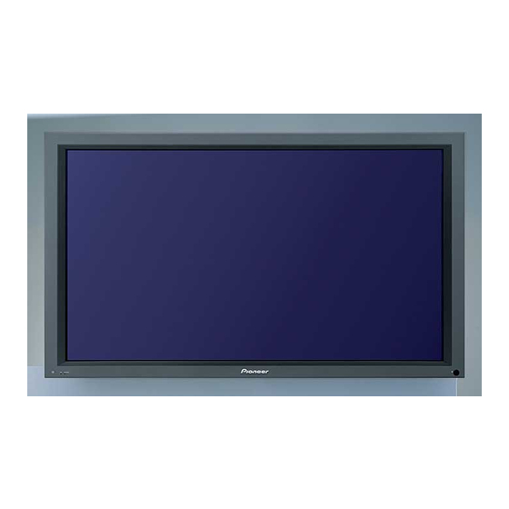
PLASMA DISPLAY
PDP-434CMX
PDP-43MXE1
PDP-43MXE1-S
THIS MANUAL IS APPLICABLE TO THE FOLLOWING MODEL(S) AND TYPE(S).
Model
Type
PDP-434CMX
LUC
PDP-43MXE1
LDFK
PDP-43MXE1-S
LDFK
This service manual should be used together with the following manual(s).
Model No.
PDP-434CMX, PDP-43MXE1
PDP-43MXE1-S
Refer to the following service manual for video card.
Model No.
PDA-5003, PDA-5004
For details, refer to "Important symbols for good services".
PIONEER CORPORATION
PIONEER ELECTRONICS (USA) INC. P.O. Box 1760, Long Beach, CA 90801-1760, U.S.A.
PIONEER EUROPE NV Haven 1087, Keetberglaan 1, 9120 Melsele, Belgium
PIONEER ELECTRONICS ASIACENTRE PTE. LTD. 253 Alexandra Road, #04-01, Singapore 159936
PIONEER CORPORATION 2004
Power Requirement
AC100 - 120V
AC100 - 240V
AC100 - 240V
Order No.
ARP3199
SCHEMATIC DIAGRAM, PCB CONNECTION DIAGRAM
Order No.
ARP3191
EXPLODED VIEWS, BLOCK DIAGRAM etc.
ARP3192
SCHEMATIC DIAGRAM, PCB CONNECTION DIAGRAM
4-1, Meguro 1-chome, Meguro-ku, Tokyo 153-8654, Japan
PDP-434CMX
Remarks
Remarks
ORDER NO.
ARP3198
Remarks
T-ZZY MAY 2004 printed in Japan
Advertisement
Chapters
Table of Contents

Related Manuals for Pioneer 434CMX - PDP - 43" Plasma Panel


Summary of Contents for Pioneer 434CMX - PDP - 43" Plasma Panel
-
Page 1: Plasma Display
PIONEER CORPORATION 4-1, Meguro 1-chome, Meguro-ku, Tokyo 153-8654, Japan PIONEER ELECTRONICS (USA) INC. P.O. Box 1760, Long Beach, CA 90801-1760, U.S.A. PIONEER EUROPE NV Haven 1087, Keetberglaan 1, 9120 Melsele, Belgium PIONEER ELECTRONICS ASIACENTRE PTE. LTD. 253 Alexandra Road, #04-01, Singapore 159936... -
Page 2: Safety Information
SAFETY INFORMATION This service manual is intended for qualified service technicians ; it is not meant for the casual do-it-yourselfer. Qualified technicians have the necessary test equipment and tools, and have been trained to properly and safely repair complex products such as those covered by this manual. Improperly performed repairs can adversely affect the safety and reliability of the product and may void the warranty. - Page 3 PRODUCT SAFETY NOTICE With the AC plug removed from an AC power source, place a Many electrical and mechanical parts in PIONEER set have jumper across the two plug prongs. Turn the AC power switch on. special safety related characteristics. These are often not evident...
- Page 4 High Voltage Generating Point Charged Section The places where voltage is 100V or more except for the charged The places where the commercial AC power is used without places described above. If the places are touched, there is a risk of passing through the power supply transformer.
- Page 5 [ Important symbols for good services ] In this manual, the symbols shown-below indicate that adjustments, settings or cleaning should be made securely. When you find the procedures bearing any of the symbols, be sure to fulfill them: 1. Product safety You should conform to the regulations governing the product (safety, radio and noise, and other regulations), and should keep the safety during servicing by following the safety instructions described in this manual.
-
Page 6: Table Of Contents
COTENTS SAFETY INFORMATION ................................1. SPECIFICATIONS ..................................2. EXPLODED VIEWS AND PARTS LIST ......................8 2.1 PACKING ....................................2.2 CHASSIS SECTION (1) ..............................2.3 CHASSIS SECTION (2) ..............................2.4 FRAME SECTION ................................2.5 MULTI BASE SECTION ..............................2.6 TERMINAL PANEL and REAR SECTION ........................ -
Page 7: Specifications
1. SPECIFICATIONS PLASMA DISPLAY (PDP-434CMX, PDP-43MXE1, PDP-43MXE1-S) General Control Light emission panel ....“43-inch” AC Plasma Panel RS-232C .......D-sub 9 pin (pin connector) 95.2 (W) x 53.6 (H) x 109.3 (diagonal) cm COMBINATION IN/OUT....Mini DIN 6 pin (x2) Number of pixels ..........1024 x 768 Accessories Power supply .. -
Page 8: Exploded Views And Parts List
2. EXPLODED VIEWS AND PARTS LIST NOTES: Parts marked by "NSP" are generally unavailable because they are not in our Master Spare Parts List. mark found on some component parts indicates the importance of the safety factor of the part. Therefore, when replacing, be sure to use parts of identical designation. - Page 9 PACKING Parts List Mark No. Description Part No. Mark No. Description Part No. Screw Set AXX1060 Upper Carton See Contrast table (2) Washer WB80FZB Carton (43) AHD3100 Hex Hole Bolt SMZ80H400FZB Pad (43U) AHA2282 Pad (43L) AHA2283 Ferrite Core See Contrast table (2) Mirror Mat AHG1284 NSP 23...
-
Page 10: Chassis Section (1)
2.2 CHASSIS SECTION (1) 17 16 15 15 PDP-434CMX... - Page 11 CHASSIS SECTION (1) parts List Mark No. Description Part No. NSP 1 P. Chassis (43) Assy AWU1098 NSP 2 43 ADDRESS Assy AWZ6793 DIGITAL VIDEO Assy AWV2100 FPC (114P) ADY1081 Flexible Cable (J201) ADD1257 Flexible Cable (J203) ADD1259 Flexible Cable (J204) ADD1260 Flexible Cable (J209) ADD1223...
-
Page 12: Chassis Section (2)
2.3 CHASSIS SECTION (2) 100V: for PDP-434CMX 200V: for PDP-43MXE1 100V PDP-43MXE1-S 200V 9 11 Upper Upper side side Upper Upper side side PDP-434CMX... - Page 13 CHASSIS SECTION (2) parts List Mark No. Description Part No. 43 X DRIVE Assy AWZ6840 43 Y DRIVE Assy AWV2022 > POWER SUPPLY Unit AXY1083 NSP 4 X CONNECTOR B Assy AWZ6799 NSP 5 X CONNECTOR A Assy AWZ6798 NSP 6 43 SCAN A Assy AWZ6796 NSP 7...
-
Page 14: Frame Section
2.4 FRAME SECTION Rear view Upper side Rear view Bottom view PDP-434CMX... - Page 15 FRAME SECTION parts List Mark No. Description Part No. IR RECEIVE Assy AWZ6855 KEY CONTROL Assy AWZ6853 LED OPT Assy AWZ6957 • • • • • • • • • • NSP 6 Front Chassis H (43) ANA1714 Front Spacer (CMX) AMR3384 Rear Frame (43M) ANG2613...
-
Page 16: Multi Base Section
2.5 MULTI BASE SECTION 27 30 13 21 Bottom view 20 16 PDP-434CMX... - Page 17 MULTI BASE SECTION parts List Mark No. Description Part No. Mark No. Description Part No. 13P/6P Wire (J104) ADX2910 AUDIO AMP Assy AWZ6848 COVER Assy AWZ6858 RGB Assy AWZ6960 Guide Rail EX AEC1994 VIDEO SLOT I/F Assy See Contrast table (2) Slot Stay ANG2608 AV I/O Assy...
-
Page 18: Terminal Panel And Rear Section
2.6 TERMINAL PANEL and REAR SECTION 36 (2/4) 36 (1/4) 36 (3/4) 36 (4/4) 20 20 20 25 18 Rear view PDP-434CMX... - Page 19 TERMINAL PANEL and REAR SECTION parts List Mark No. Description Part No. Mark No. Description Part No. > Power Switch (S1) ASG1094 COMM SLOT I/F Assy AWZ6850 Housing Wire (MX)(J116) ADX2896 COMM SLOT Assy AWZ6849 COMM Stay A ANG2605 > AC Inlet (CN1) AKP1244 COMM Stay B...
-
Page 20: Front Section
2.7 FRONT SECTION PDP-434CMX Only PDP-434CMX... - Page 21 Mark No. Description Part No. Mark No. Description Part No. Flexible Cable (J211) ADD1265 SIDE KEY Assy AWZ6852 Flexible Seal AEH1074 Pioneer Name Plate AAM1101 Screw ABZ30P060FMC Panel Cushion V (43M) AED1254 Screw APZ30P080FZK Panel Cushion H (43M) AED1253 Screw APZ30P120FZK >...
-
Page 22: Panel Chassis (43) Assy (Awu1098)
2.8 PANEL CHASSIS (43) ASSY (AWU1098) Panel Chassis (43) Assy (AWU1098) • Parts List Mark No. Description Part No. 1..43 ADDRESS Assy AWV2120 2..43 ADDRESS Assy AWZ6793 1..43 SCAN FUKUGO Assy AWV2023 2..43 SCAN A Assy AWZ6796 2..43 SCAN B Assy AWZ6797 2..X CONNECTOR A Assy AWZ6798... -
Page 23: Pdp Service Assy 434Cmx (Awu1094)
2.9 PDP SERVICE ASSY 434CMX (AWU1094) PDP SERVICE Assy (AWU1094) • Parts List Mark No. Description Part No. P. Chassis (43) Assy AWU1098 Front Chassis H (43) ANA1714 F Chassis VL (43M) ANA1755 F Chassis VR (43M) ANA1756 Rear Frame (43M) ANG2613 Sub Frame L Assy (43M) ANG2623... -
Page 24: Block Diagram And Schematic Diahram (Refer To "Service Manual: Arp3199")
3. BLOCK DIAGRAM AND SCHEMATIC DIAHRAM 3.1 BLOCK DIAGRAM 3.1.1 OVERALL BLOCK DIAGRAM (1/2) DRIVER IC DRIVER IC DRIVER IC DRIVER IC DRIVER IC DRIVER IC DRIVER IC DRIVER IC IC1552 IC1553 IC1554 IC1555 IC1552 IC1553 IC1554 IC1555 V+5V V+5V V+9V V+60V V+9V... - Page 25 DRIVER IC DRIVER IC DRIVER IC DRIVER IC DRIVER IC DRIVER IC DRIVER IC DRIVER IC IC1552 IC1553 IC1554 IC1555 IC1552 IC1553 IC1554 IC1555 V+5V V+5V V+9V V+60V V+9V V+60V V+3V_IC5 V+3V_IC5 V+3V_LVDS V+3V_PLL V+ADR V+3V_LVDS V+3V_PLL V+ADR RESONANCE RESONANCE IC1501 IC1501 BLOCK...
-
Page 26: Overall Block Diagram (2/2)
3.1.2 OVERALL BLOCK DIAGRAM (2/2) CN5002 V+16 AV I/O ASSY IC7606 IC5002 +L/+R INPUT 1 IC7602 IC7605 AUDIO IN IC5003 IC7603 IC7601 POWER AMP INPUT 2 VOLUME IC7607 SELECTOR AUDIO IN -L/-R V+12V V+3V V+6.5V AUDIO AMP ASSY IC7608 AUDIO OUT SELECTOR LEG_R LED OPT... -
Page 27: Rgb Assy
SP TERMINAL L ASSY SP TERMINAL R ASSY SIDE KEY CN5002 FAN L FAN R ASSY CN7408 CN7404 CN7402 CN7205 V+1V V+3V V+3V V+6.5V _STB V+16.5V FAN_12V RGB H/V IC5701 RGB H/V PD6435A IC7004 IC7101 PE5362A PD5855A CN5001 IC5801 PD6435A TXD_MD RXD_MD IC6403... -
Page 28: Signal Route
3.1.3 SIGNAL ROUTE MANTA PROCESS SYNC PROCESS SYNC PDP-434CMX... -
Page 29: Drive Assy
3.1.4 43 Y DRIVE ASSY 43 Y DRIVE ASSY 43 SCAN B ASSY IC5V CLK1 Photo Coupler Photo Coupler Photo Coupler CLK2 Photo Coupler 43 SCAN A ASSY Photo Coupler Photo Coupler Photo Coupler VSUS IC2203 YPR-U YSOFT-D YPR-U YSOFT-D YSUS-G YSUS-G YSUS-B... -
Page 30: Drive Assy
3.1.5 43 X DRIVE ASSY 43 X DRIVE ASSY XSUS-G XSUS-G XSUS-B XSUS-B XSUS-U2 XSUS IC1101 Mask Module L1102 XSUS-D2 VSUS PSUS IC1203 XSUS-U1 STK795-510 DRIVER XSUS-D1 L1103 XSUS-MSK XSUS-D2 16.5V XCP-MSK IC1102 L1104 XSUS-U1 XNR-D XSUS_PD DRIVER Mask Module XDD_PD L1105 VSUS... -
Page 31: Digital Video Assy
3.1.6 DIGITAL VIDEO ASSY Works by passive standby power Works by active standby power CN5001 43 ADDRESS ASSY x8 DIGITAL VIDEO ASSY Video signal LVDS (R,G,B) x10bit x2 Sync. signal 3-wire serial down HD, VD, CLK, DE 3-wires serial up PANEL SIZE Signal for JTAG... -
Page 32: Av I/O Assy
3.1.7 AV I/O ASSY AV I/O ASSY V+3V V+12V IC7601 TC4052BFT CN7601 AUDIO IC7606 IC7603 PD3869AF SELECTOR AUDIO VOL CN7602 IC7602 IC7605 L+ R+ INPUT 1 BUFFER BUFFER AUDIO IN V+6.5V CN7501 INPUT 2 SCL_AV SDA_AV AUDIO IN V+12V IC7607 CN8702 REG. -
Page 33: Rgb Assy
3.1.8 RGB ASSY MANTA PROCESS SYNC PROCESS SYNC INPUT1 INPUT5 HD/VD HD/VD PDP-434CMX... -
Page 34: Audio Amp And Comm Slot Assys
3.1.9 AUDIO AMP and COMM SLOT ASSYS AUDIO AMP ASSY IC5003 LA4625 CN5003 BAL → UNBAL POWER AMP CN5001 L_OUT + L_OUT - R_OUT + R_OUT - V+3.3V STBY AMUTE A_NG DETECT TEMP3 TEMP3 V+12V IC5001 V+12V_D SI-8120S CN5002 V+6.5V V+16.5 CONVERTER V+3.3V... -
Page 35: Waveforms
3.2 WAVEFORMS DIGITAL VIDEO ASSY (4/6) • DIGITAL I/F BLOCK CH1: K5003 (VD) CH1: K5002 (HD) CH2: K5002 (HD) CH2: K5004 (DE) V: 2V/div. H: 2msec/div. V: 2V/div. H: 2µsec/div. CH1: K5003 (VD) CH1: K5002 (HD) CH2: K5002 (HD) CH2: K5004 (DE) V: 2V/div. - Page 36 RGB ASSY (2/10, 3/10, 4/10) MAIN AD BLOCK, MAIN LPF BLOCK, SUS LPF&AD BLOCK Input: INPUT 1 Signal: RGB, XGA 60 Hz, Color-bar = to *, _ : With two screens, a SUB screen chooses INPUT1 and observes it. CH1: IK6012 (PLLHD_MAIN) CH1: K6601(PLLHD_SUB) CH1: Foot of R6628 (DATACK) K6404 (HD1_MAIN)
- Page 37 AV I/O ASSY (1/3) AUDIO AMP ASSY • AUDIO • AV/IO BLOCK • VIDEO • AUDIO Input: INPUT 1 Input: INPUT 1 Input: INPUT 1 Signal: 200mVrms, 1 kHz input, Signal: RGB, XGA 60 Hz, Color-bar Signal: 200mVrms, 1 kHz input, VOL MAX VOL MAX CH1: JA7606-pin 13 (HD) CH1: CN7601-pin 14 (+L_OUT)
- Page 38 43 X DRIVE ASSY, 43 Y DRIVE ASSY and 43 SCAN A ASSY SUS BLOCK, X LOGIC BLOCK, Y LOGIC BLOCK, Y SUS BLOCK, SCAN A BLOCK Drive Output Waveform (1 field,color-bar) Control Signal (Sustain Waveform Gen.) CH1: R1226 (XPSUS) - K1201 (SUSGND) CH2: K2016 (YSUS-G) - K2010 (DGND) CH3: K2025 (YSUS-U1) - K2010 (DGND) (43 X DRIVE ASSY)
- Page 39 43 ADDRESS ASSY • ADR RESONANCE BLOCK (VIDEO) CH1: IC1601-pin 2 (ADR_B2) CH1: Q1601-pin 4 (ADR_B2) CH1: Q1601 Drain (V+ADR) CH2: IC1603-pin 4 (ADR_U1) CH2: Q1603-pin 4 (ADR_U1) CH2: Q1603 Source CH3: IC1603-pin 2 (ADR_D1) CH3: Q1603-pin 2 (ADR_D1) CH3: Q1602 Source V: 1V/div.
- Page 40 43 ADDRESS ASSY • ADR LOGIC BLOCK CH1: IC1552-pin 18 (CLK input) CH2: IC1552-pin 16 (LE input) CH3: IC1552-pin 9 (DATA input) V: 1V/div. (Input: VIDEO, Signal: Color-bar) 2msec/div. 200nsec/div. CH1: IC1552-pin 23 (HBLK input) CH2: IC1552-pin 19 (LBLK input) CH3: IC1552-pin 25 (HZ input) V: 1V/div.
-
Page 41: Voltages
3.3 VOLTAGES • Voltages CN5601 (D1) No. Signal Name I/O Signal Description Voltages at NTSC Signal Input +12V +12V power input +12VDC +12V +12V power input +12VDC − GND_D − GND_D Power down signal 0VDC VSUS adjustment signal VSUS_ADJ PS_PD Power-down detecting signal of POWER SUPPLY block 0VDC RELAY... - Page 42 RGB ASSY POWER SUPPLY ASSY RGB ASSY VIDEO SLOT I/F ASSY R1 (CN7404) R4 (CN7407) VS1 (CN8951) Voltage Voltage Name Name Name Name V+16.5V 16.7 V+16.5V V+12V 12.9 V+12V V+13V 13.6 V+13V V+12V 12.9 V+12V V+13V 13.6 V+13V V+12V 12.9 V+12V V+12V 12.9...
- Page 43 RGB ASSY RGB ASSY R9 (CN5701) R9 (CN5701) Name Name AV I/O IF ASSY AV I/O IF ASSY AV I/O ASSY AV I/O ASSY CN2102, AV6 (CN2101) CN8705 CN2102, AV6 (CN2101) CN8705 Voltage Voltage Name Name Name Name N.C. N.C. BA_DVI5 0/3.3 BA_DVI5...
- Page 44 RGB ASSY VIDEO SLOT I/F ASSY RGB ASSY R11 (CN7410) VS3 (CN8955) R9 (CN5701) Voltage Name Name Name AV I/O IF ASSY AV I/O ASSY CN2102, AV6 (CN2101) CN8705 Voltage DSUBV DSUBV Name Name GA_DVI6 0/3.3 GA_DVI6 IN5_VD IN5_VD GA_DVI4 0/3.3 GA_DVI4 GA_DVI2...
- Page 45 RGB ASSY VIDEO SLOT I/F ASSY RGB ASSY VIDEO SLOT I/F ASSY R12 (CN7405) VS4 (CN8953) R12 (CN7405) VS4 (CN8953) Voltage Voltage Name Name Name Name RB6_IC1 0/3.3 RB6_IC1 BA4_IC1 0/3.3 BA4_IC1 RB7_IC1 0/3.3 RB7_IC1 BA3_IC1 0/3.3 BA3_IC1 BA2_IC1 0/3.3 BA2_IC1 BA1_IC1 0/3.3...
- Page 46 AV I/O ASSY LED OPT ASSY COMM SLOT I/F ASSY IR ASSY AV3 (CN8703) KY1 (CN9651) CS4 (CN8901) RE1 (CN4901) Voltage Voltage Name Name Name Name V+3STB V+3STB V+3STB V+3STB LED_ G LED_ G LED_ R LED_ R AC_ DET AC_ DET COMM SLOT I/F ASSY COMM SLOT ASSY...
- Page 47 COMM SLOT I/F ASSY VIDEO SLOT I/F ASSY VIDEO SLOT I/F ASSY VIDEO SLOT 1 and 2 ASSY VS5 (CN8954) CN7902 CS3 (CN8903) VS2 (CN8952) Voltage Voltage Name Name Name Name GB1_IC1 0/3.3 GB1_IC1 FIRST_RXD FIRST_RXD GB2_IC1 0/3.3 GB2_IC1 GET_UART GET_UART GB3_IC1 0/3.3...
- Page 48 VIDEO SLOT I/F ASSY VIDEO SLOT 1 and 2 ASSY VIDEO SLOT I/F ASSY VIDEO SLOT 1 and 2 ASSY VS5 (CN8954) CN7902 VS5 (CN8954) CN7902 Voltage Voltage Name Name Name Name SCL_VS SCL_VS RA0_IC1 0/3.3 RA0_IC1 SDA_VS SDA_VS V+12V 12.9 V+12V VSEPSCL...
-
Page 49: Pcb Parts List
5. PCB PARTS LIST NOTES: Parts marked by "NSP" are generally unavailable because they are not in our Master Spare Parts List. mark found on some component parts indicates the importance of the safety factor of the part. Therefore, when replacing, be sure to use parts of identical designation. When ordering resistors, first convert resistance values into code form as shown in the following examples. - Page 50 Mark No. Description Part No. Mark No. Description Part No. CAPACITORS D1608,D1609,D1617,D1618 EC10UA20 C3201,C3211,C3212,C3222,C3223 ACG1088 D1610,D1611,D1616,D1619,D1620 EC11FS2 C3233,C3234,C3244,C3245 ACG1088 D1604,D1612 MA126 C3255,C3256,C3266 (0.1/250V) ACG1088 D1602,D1606,D1607,D1614,D1615 UDZS15B C3203,C3204,C3214,C3215,C3226 CCSRCH101J50 D1621,D1622 UDZS24B C3228,C3237,C3239,C3247,C3251 CCSRCH101J50 COILS AND FILTERS C3258,C3259 CCSRCH101J50 L1601,L1602 ATH1135 C3206,C3217,C3232,C3243,C3249 CCSRCH181J50 C3261 CCSRCH181J50...
- Page 51 Mark No. Description Part No. Mark No. Description Part No. Q1102,Q1103,Q1111,Q1112,Q1114 2SK3560 L1202 LFEA100J Q1105,Q1106,Q1108,Q1109 2SK3723 L1203,L1206 LFEA470J CAPACITORS Q1101,Q1104,Q1107,Q1110 CPH5506 D1109,D1122 1SS302 C1214-C1217,C1227-C1230 ACE1163 D1112,D1119 1SS355 C1233 (0.12/250V) ACE1169 D1101,D1102,D1104,D1105 EC11FS4 C1244 (0.1/250V) ACE1170 D1107,D1108,D1111,D1114-D1117 EC11FS4 C1209 (0.1/630V) ACG1092 C1219,C1231 ACH1359 D1120,D1121,D1127,D1128...
- Page 52 Mark No. Description Part No. Mark No. Description Part No. OTHERS Q2213 2SC2412K Q2202,Q2203,Q2211,Q2212,Q2214 2SK3560 1002 CARD SPACER AEC1957 Q2205,Q2206,Q2208,Q2209 2SK3723 1001 DRIVE SIRICON SHEET A AEH1062 1001 PLATE X ANG2622 Q2201,Q2204,Q2207,Q2210 CPH5506 1001 DRIVE HEATSINK A ANH1613 D2209,D2223 1SS302 1001 SCREW BMZ30P080FZK D2228,D2229...
- Page 53 Mark No. Description Part No. Mark No. Description Part No. CAPACITORS Q2415 HN1C01FU D2430 1SS301 C2309-C2312,C2326,C2327 ACE1163 D2410,D2419,D2436 1SS302 C2329,C2330 (1.5/300V) ACE1163 D2409,D2418 1SS355 C2314 (0.047/250V) ACE1165 C2302 (0.1/630V) ACG1092 D2404-D2407 EC11FS2 C2316,C2331 (300/280V) ACH1359 D2403,D2414 EC11FS4 D2402 EC8FS6 C2303 (22/315V) ACH1361 D2427 RD91PA...
- Page 54 Mark No. Description Part No. Mark No. Description Part No. RGB ASSY R7478 RS1/16S8201F [RGB BLOCK] Other Resistors RS1/16S###J SEMICONDUCTORS IC7411 BD6522F OTHERS > IC7412 M5291FP CN7405 12P PLUG AKM1203 IC7402 MM1522XU CN7401 15P PLUG AKM1232 IC7401 MM3012XN CN7410 50P PLUG AKM1270 IC7404 NJM12904V...
- Page 55 Mark No. Description Part No. Mark No. Description Part No. [MAIN AD BLOCK] C6646, C6656-C6661 CKSRYB471K50 C6609, C6614, C6623 CKSRYB473K16 SEMICONDUCTORS IC6001 CXA3516AR C6642 CKSRYB474K10 IC6002-IC6008 TC74LCX541FT C6641 CKSRYB562K50 Q6001 2SC4116 C6602 CKSRYB822K50 D6001 1SS355 C6601 CKSRYB823K16 C6605-C6607, C6610, C6613 CKSSYF104Z16 COILS AND FILTERS L6001...
- Page 56 Mark No. Description Part No. Mark No. Description Part No. R5837, R5844, R5883 RAB4CQ103J RESISTORS Other Resistors RS1/16S###J R5845, R5850, R5851, R5853, R5855 RAB4CQ470J R5857, R5859, R5861-R5863, R5876 RAB4CQ470J Other Resistors RS1/16S###J [MAIN UCOM BLOCK] SEMICONDUCTORS OTHERS IC7205 24LC128(I)SN X5801 CERAMIC RESONATOR ASS1169 IC7201, IC7204 74VHCT00AMTC...
- Page 57 Mark No. Description Part No. Mark No. Description Part No. > IC7604 NJM78L09UA CN7601 15P PLUG KM200NA15 IC7601, IC7608 TC4052BFT [IF UCOM BLOCK] IC7612 TC74AC04FT IC7611 TC74VHCT541AFT SEMICONDUCTORS Q7602, Q7605, Q7702 2SC4116 IC8705 24LC01B Q7603 DTA124EUA IC8702 HD64F3687FP IC8703 PST9230N Q7604, Q7606-Q7608 DTC124EUA IC8701...
- Page 58 Mark No. Description Part No. Mark No. Description Part No. C7503, C7506 CKSRYB222K50 5001 SCREW VBB30P100FNI C7514, C7520, C7573-C7577 CKSRYB471K50 KN5001, KN5002 VNF1084 C7501, C7509, C7513, C7515, C7517 CKSSYF104Z16 (WRAPPING TERMINAL) C7519, C7521, C7523, C7525, C7527 CKSSYF104Z16 C7529, C7531, C7533, C7536 CKSSYF104Z16 COMM SLOT ASSY C7539, C7540, C7543-C7545, C7547...
- Page 59 Mark No. Description Part No. Mark No. Description Part No. CAPACITORS C4903 CKSRYB102K50 C4907 CKSRYB103K50 C8952 CEHAT470M16 C4902, C4904 CKSSYF104Z16 C8953 CKSSYF104Z16 RESISTORS RESISTORS Other Resistors RS1/16S###J Other Resistors RS1/16S###J OTHERS CN8953 120P SOCKET AKP1219 SP TERMINAL L ASSY CN8954 184P PCI BUS SOCKET AKP1251 CN8955 50P SOCKET AKP1253...
- Page 60 Mark No. Description Part No. Mark No. Description Part No. DIGITAL VIDEO ASSY Q5301 RN1901 [DIGITAL IF BLOCK] D5301-D5310 1SS302 COILS AND FILTERS F5001, F5002, F5004, F5005 ATF1194 CAPACITORS C5320 CCSRCH470J50 RESISTORS C5304, C5307 CKSRYB102K50 R5101-R5115, R5131 RAB4C470J C5311, C5314 CKSRYB104K16 Other Resistors RS1/16S###J...
- Page 61 Mark No. Description Part No. D5602, D5603, D5609, D5610 1SS355 D5601 HZU2.2B D5604 UDZS5.1B CAPACITORS C5601, C5603, C5607, C5614, C5616 ACH1394 (100microF/16V) C5602, C5604, C5615, C5617 CKSRYB103K50 C5605, C5606, C5610 CKSSYF104Z16 RESISTORS R5601 ACN1162 R5627 ACN1168 Other Resistors RS1/16S###J OTHERS >...
-
Page 62: Adjustment
6. ADJUSTMENT 1. At shipment, the unit is adjusted to its best conditions. Normally, it is not necessary to readjust even if an assembly is replaced. If the adjustment is shifted or if it becomes necessary to readjust because of part replacement, etc., perform the adjustment as described below. 2. -
Page 63: Service Factory Mode
6.2 SERVICE FACTORY MODE Commands in Service/Factory mode must be issued using the remote control unit supplied with the Plasma Display. State Transition Diagram At standby Normal operation mode POWER (AA1C/AA1B) FACT (AA5F) FACT (AA5F) [POF] FACT FACT (AA5F) MENU (AA8B) (Refer to the following step.) [FAY] [FAN]... -
Page 64: How To Enter Factory Mode
6.3 HOW TO ENTER FACTORY MODE For adjustments, it is necessary to enter Service/Factory mode. There are two ways to enter Service/Factory mode: by using the remote control unit, or by using RS232C commands from your PC. When the unit is in Standby (STB) Mode •... - Page 65 Operation when Service/Factory mode is entered Functions whose settings are set to OFF The settings of the following functions are set to OFF when Service/Factory mode is entered (including when this mode is entered by receiving the FAY command): • SPLIT (The display will become that of the main input.) •...
- Page 66 Main-item indications Four parameters are displayed: 1 2 3 4 5 6 7 8 9 10 11 12 13 14 15 16 17 18 19 20 21 22 23 24 25 26 27 28 29 30 31 32 33 34 35 36 37 38 39 40 I N F O R M A T I O N I N 1 –...
- Page 67 ¶ SIG-Mode Table The signal mode is displayed in three characters: First character: Resolution of the input signal (numerics for the video signals, and alphabetics for the PC signals) Second character: Grouping of the vertical frequencies Reference Vertical 2nd Character Area Remarks Frequency...
- Page 68 SIG-Mode table for PC signals Vertical Freq. Horizontal Freq. Dot Clock SIG-Mode Signal Type Remarks fv (Hz) fh (kHz) (MHz) ∗ 640 × 400 Former 720 × 400 56.422 24.825 21.052 ∗ 720 × 400 Former 640 × 400 70.087 31.469 28.322 ∗...
-
Page 69: The Flash Memory Versions For Each Device Are Displayed
INFORMATION mode Select the main item "INFORMATION" using the MUTE key then select the subitems shown in the table below using the 5 or ∞ key. ¶ Operation items No. Function / Display Content 232C Command VERSION (1) The flash memory versions for each device are displayed (1) The type of video card inserted in the slot is displayed: VERSION (2) SERIAL... -
Page 70: Serial
SLOT-DET (No indication) No card inserted 4G 5003B When the Pioneer PDA-5003 Standard Video Card is inserted. 4G 5004R When the Pioneer PDA-5004 Standard Video Card is inserted. 3G TYPE ∗ When a PDP-503CMX-based OEM video card is inserted ∗ = A to H When a PDP-504CMX-based OEM video card is inserted ∗... -
Page 71: Panel Pd
4. PANEL PD 1 2 3 4 5 6 7 8 9 10 11 12 13 14 15 16 17 18 19 20 21 22 23 24 25 26 27 28 29 30 31 32 33 34 35 36 37 38 39 40 N F O R M A T I O N I N 1 –... -
Page 72: Panel Sd
5. PANEL SD 1 2 3 4 5 6 7 8 9 10 11 12 13 14 15 16 17 18 19 20 21 22 23 24 25 26 27 28 29 30 31 32 33 34 35 36 37 38 39 40 N F O R M A T I O N I N 1 –... -
Page 73: Temperature
6. TEMPERATURE 1 2 3 4 5 6 7 8 9 10 11 12 13 14 15 16 17 18 19 20 21 22 23 24 25 26 27 28 29 30 31 32 33 34 35 36 37 38 39 40 N F O R M A T I O N I N 1 –... -
Page 74: Backup Eeprom
10. BACKUP EEPROM When the DIGITAL VIDEO Assy is to be replaced, the adjustment values in it are temporarily stored in the backup ROM then are written on the new Assy after replacement. 1 Check if adjustment has been made on the DIGITAL VIDEO Assy or not (i.e., in the state of a new service part), and if the data on any adjustment values are retained in the backup ROM or not. - Page 75 Adjustment of corresponding route unevenness Basically, only replacement of service parts is required, and adjustment is not required. Adjustment Function Parameter Name No. Command in Factory CVY GAIN IC1 MAIN GAIN adjustment (switching routes with the SWM [main] and SWS [sub] commands) CVY OFFSET IC1 MAIN OFFSET adjustment (switching routes with the SWM [main] and SWS [sub]...
- Page 76 Reference: Commands for adjustment of differences in signals and memory cells used for storing adjustment values • Basically no adjustment is required for the Service Assy, as it is properly adjusted before shipment. Adjustment values to be stored in the EEPROM Adjustment values to be stored in the EEPROM of the AV I/O (INDIVIDUAL mode) of the RGB (COMMON mode)
- Page 77 INDIVIDUAL ADJ. mode 1 2 3 4 5 6 7 8 9 10 11 12 13 14 15 16 17 18 19 20 21 22 23 24 25 26 27 28 29 30 31 32 33 34 35 36 37 38 39 40 I N D I V I D U I N 1 –...
- Page 78 1. COMMON-RGB1 1 2 3 4 5 6 7 8 9 10 11 12 13 14 15 16 17 18 19 20 21 22 23 24 25 26 27 28 29 30 31 32 33 34 35 36 37 38 39 40 C OMMO N –...
- Page 79 3. COMMON-PANEL1 1 2 3 4 5 6 7 8 9 10 11 12 13 14 15 16 17 18 19 20 21 22 23 24 25 26 27 28 29 30 31 32 33 34 35 36 37 38 39 40 C OMMO N –...
- Page 80 4. COMMON-PANEL2 1 2 3 4 5 6 7 8 9 10 11 12 13 14 15 16 17 18 19 20 21 22 23 24 25 26 27 28 29 30 31 32 33 34 35 36 37 38 39 40 C OMMO N –...
- Page 81 1. PATTERN MASK 2. FULL MASK 1 2 3 4 5 6 7 8 9 10 11 12 13 14 15 16 17 18 19 20 21 22 23 24 25 26 27 28 29 30 31 32 33 34 35 36 37 38 39 40 O P T I O I N 1 –...
- Page 82 Full Mask Function/ Corresponding Content Display RS-232C Command Mask mode: OFF Raster – White Raster – Red Raster – Green Raster – Blue Raster – Black Raster – Cyan Raster – Mazenta Raster – Yellow 10 M59 Raster – Cyan 274 11 M60 Raster –...
- Page 83 5. INTEGRATOR MODE The setting can be changed using the 2 or 3 key. Function/ Corresponding Content Display RS-232C Command – ENABLE Permitting INTEGRATOR MODE (initial setting) – DISABLE Prohibiting INTEGRATOR MODE INITIALIZE mode 1 2 3 4 5 6 7 8 9 10 11 12 13 14 15 16 17 18 19 20 21 22 23 24 25 26 27 28 29 30 31 32 33 34 35 36 37 38 39 40 I N I T A L I Z E I N 1 –...
- Page 84 1. FINAL SETUP 1 2 3 4 5 6 7 8 9 10 11 12 13 14 15 16 17 18 19 20 21 22 23 24 25 26 27 28 29 30 31 32 33 34 35 36 37 38 39 40 I N I T A L I Z E I N 1 –...
- Page 85 Item (operation) Factory setting Remarks Integrator PICTURE Default setting for all adjustment items For each input function menu WHITE BAL. Default setting for all adjustment items For each input function setting For each input function SCREEN Default setting for all adjustment items VIDEO DRE MID The screen-size setting will be one of the factory-preset GRADATION...
- Page 86 P-SLOT (PDA-5003/ PDA- 5004) made by Pioneer ?: Operable according to the setting ×: The corresponding Video card will be treated as an incompatible Video card. • When a disallowed video card is inserted, the power is not turned on, and the red and green LEDs flash alternatively.
-
Page 87: Command Description
6.4 COMMAND DESCRIPTION About GET Command • Operation description of GET command Conditions under which GET commands are enabled Most of the GET commands are enabled at any time, regardless of unit's being on/off or in Factory or Normal mode. However, some GET commands must be issued while the power is on to acquire correct data. - Page 88 GS1: Returning information on the model and the version of the software Data Order Size Data on the display 3 byte Breakdown of the data on the display Version of the module microcomputer 4 byte Model Data Version of the IC4-MANTA 4 byte PDP-504CMX series Sequence version (50VIDEO)
- Page 89 GPD: Power-down information Data Order Size Order Data Size Latest "1st PD" data 1 byte Fifth latest “1st PD” data 1 byte Latest "2nd PD" data 1 byte Fifth latest “2nd PD” data 1 byte Data of hour meter for the latest PD 7 byte Data of hour meter for the fifth latest PD 7 byte...
- Page 90 GNG: NG history Data Order Size Order Data Size Latest SD data 1 byte Fifth latest SD data 1 byte Data of subcategory for the latest SD 1 byte Data of subcategory for the fifth latest SD 1 byte Data of hour meter for the latest SD 7 byte Data of hour meter for the fifth latest SD 7 byte...
- Page 91 GS2: Status information Data Order Size Remarks Notifying of switching to Standby mode 1 byte 1: Successfully switched to Standby mode Whether the unit has already been adjusted or not 1 byte 0: Adjusted, 1: Not adjusted With/without backup of adjustment data 1 byte 0: With backup, 1: Without backup Power-down information...
- Page 92 GPM: Value of the pulse meter Note: The number of electric discharges at each block is Data Order Size displayed. The first digit represents the number of Pulse meter (Block area 1) 10 byte tens of thousands. Pulse meter (Block area 2) 10 byte Pulse meter (Block area 3) 10 byte...
- Page 93 LIST OF RS-232C COMMAND Validity of Lower Upper Direct Command Operation Remarks limit limit Numeric Input Adjusting power consumption AD CONTRAST adjustment Audio MUTE OFF Audio MUTE ON Execution of auto setup The values for positions are not stored in memory in Factory mode. Transmitting the backup data to the DIGITAL VIDEO Assy Indicate a current baudrate BRAS01...
- Page 94 Validity of Lower Upper Direct Command Operation Remarks limit limit Numeric Input Obtaining the serial no. Obtaining the P ON COUNTER value Obtaining power-down information Obtaining the PULSE METER data Obtaining the PD polling log Obtaining the PANEL W/B data Obtaining the version data for each device Obtaining the temperature data and unit state Data of module microcomputer system...
- Page 95 Validity of Lower Upper Raster-red Direct Command Operation Remarks limit limit Numeric Input Raster-green Raster-blue Raster-black Raster-cyan Raster-magenta Raster-yellow Raster-cyan 274 Raster-50 flesh color Raster-50 light purple Raster-50 sky blue Raster-red 779 Raster-cyan 218 Raster-cyan 448 Raster-43 flesh color Raster-red 640 Raster-magenta 98 Raster-43 sky blue 1 Raster-43 sky blue 2...
- Page 96 Validity of Lower Upper Direct Command Operation Remarks limit limit Numeric Input Setting the signal format to PC FORMAT1 (VGA or SFTS01 XGA or SXGA or 720-PC) Setting the signal format to PC FORMAT2 (WVGA or SFTS02 WXGA or SXGA+) SFTS03 Setting the signal format to (VIDEO) 525p or 750p SFTS04...
-
Page 97: General Information
7. GENERAL INFORMATION 7.1 DIAGNOSIS 7.1.1 CONFIGURATION OF THE PC BOARD DIGITAL VIDEO Assy PANEL SENSOR Assy 43 ADDRESS 43 ADDRESS 43 ADDRESS 43 ADDRESS Assy Assy Assy Assy X CONNECTOR 43 SCAN B B Assy Assy POWER SUPPLY Unit 43 Y DRIVE 43 X DRIVE Assy... -
Page 98: Diagnosis For Shutdown And Power-Down By Led
7.1.2 DIAGNOSIS FOR SHUTDOWN AND POWER-DOWN BY LED • Operation statuses indicated by LEDs Standby GREEN Normal Power on GREEN 0.5s 0.5s 0.5s 3.0s Power-down GREEN Abnormality Shutdown 0.5s 0.5s 0.5s 3.0s GREEN 0.3s Interval 0.3s Slot Protect 0.3s 1.5S 0.3s GREEN Note:... -
Page 99: Mo D U L E
• Identification of locations having abnormality by the number of times the LEDs flash On Shutdown and power-down Shutdown • Operation: When the microcomputer detects any abnormality, it forcibly shuts the unit off. • LED indication: The LED flashes in green. Note: The LED flashes regardless of the FRONT INDICATOR setting on the Integrator menu. - Page 100 E_SCL E_SDA PDP-434CMX...
- Page 101 PDP-434CMX...
- Page 102 PDP-434CMX...
- Page 103 • Block diagram of the power-down signal system PDP-434CMX...
- Page 104 • Power-down diagnosis (defective points) PDP-434CMX...
-
Page 105: Processing At The Time Of Abnormalities
7.1.3 PROCESSING AT THE TIME OF ABNORMALITIES Fan and temperature sensor Circuitry SENSOR ASSY DIGITAL VIDEO ASSY TEMP1 MODULE SENSOR UCOM RGB ASSY FAN_NG SP TERMINAL L ASSY FAN0 TEMP3 MAIN SENSOR DRIVE UCOM TEMP2 SENSOR Port monitoring specifications Shutdown Control Port Assign... -
Page 106: Power On/Off Function For The Large-Signal System
7.1.5 POWER ON/OFF FUNCTION FOR THE LARGE-SIGNAL SYSTEM Function: Only the power for the low voltage lines (16 V, 12 V, and 6.5 V) is on, and the power for the high voltage lines (VSUS, VADR) is off. Usage: 1. Use when only an operational check for the low voltage lines is required, such as when making repairs. 2. -
Page 107: Backup The Adjustment Values For The Main Unit
7.1.6 BACKUP THE ADJUSTMENT VALUES FOR THE MAIN UNIT Outline The data on the adjustment values for the main unit are stored in an EEPROM (IC5206, 4 kbits) on the DIGITAL VIDEO Assy. Part of the data (area A in the figure below) are automatically copied to an EEPROM (IC7102, 2 kbits) mounted on the RGB Assy for backup. When the DIGITAL VIDEO Assy is replaced, the backup data on the adjustment values for the main unit stored in the RGB Assy can be copied to the new DIGITAL VIDEO Assy, thus enabling you to omit newly performing adjustments on the main unit. - Page 108 3. When a repaired DIGITAL VIDEO Assy is mounted on the original unit (reuse of the repaired DIGITAL VIDEO Assy) Changing of keywords is not required. After the repaired DIGITAL VIDEO Assy is mounted in the original unit, the unit can operate with its latest adjustment values.
-
Page 109: Troubleshooting
7.1.7 TROUBLESHOOTING Video Image of INPUT 1 not Image of INPUT 3 not displayed (RGB) displayed (Y/C) VIDEO SLOT Assy - = ~ ! @ Is INPUT 1 selected Select INPUT 1. Is a signal output from IC6255 Check communication with the input selector? between the input on the VIDEO SLOT Assy? - Page 110 Audio No sound from the speakers Are the SP cables Connect the SP cables properly connected? properly then check again. Is sound muting set? Cancel muting then check again. Is the volume set to 0? Raise the volume then check again. AUDIO AMP Assy # $ Check the connection between Is a signal output from IC5003...
-
Page 111: Disassembly
7.1.8 DISASSEMBLY Rear Case (43M), Front Case 434 (CMX) Rear case (43M) Remove the grip by removing the four screws. Remove the six screws. Remove the sixteen screws. Note : When reattaching the rear case (43M), first attach the screws for the holes indicated with ∗1 to place Grip Grip the rear case (43M) in the correct position. - Page 112 Multi Base Section Diagnosis of AV I/O Assy Remove the three nuts. Remove the six hexagonal screws. Remove the one screw. AV I/O Assy Remove the one pin grommet. Remove the AV I/O Assy with the AV I/O I/F Assy. ×2 ×2 ×2...
- Page 113 X CONNECTOR A Assy, B Assy, 43 SCAN A Assy and B Assy X CONNECTOR A and B Assy Remove the one nylon rivet. 43 X DRIVE Assy Remove the one screw. Note: Be sure to remove this screw. If you don't, the connector on the LED OPT Assy may be damaged.
-
Page 114: Ic Informatiion
7.2 IC INFORMATIION • The information shown in the list is basic information and may not correspond exactly to that shown in the schematic diagrams. List of IC BA10393F, BA10358F, STK795-510, STK795-511, MBM29PL160BD-75PFTN, M30626FHPGP-P,PD5856A, AN5870SB, AD9883AKST-110, SM5301BS, BA7078AF, HY57V643220CT-7, MBM29PL3200BE70PFV,CXA3516R, SII1161BCTG100, LA4625 BA10393F (43 X DRIVE ASSY : IC1103) (43 Y DRIVE ASSY : IC2211) - Page 115 STK795-510 (43 X DRIVE ASSY: IC1203, IC1207) • PDP Mask Module IC Block Diagram SUB-GND N.C. SUS-B N.C. DRIVER SUS-G N.C. VSUS PSUS VSUS PSUS VSUS PSUS VSUS PSUS VSUS PSUS SUSGND SUSGND PSUS SUSGND PSUS SUSGND PSUS SUSGND PSUS PSUS SUSOUT SUSOUT...
- Page 116 MBM29L160BD-75PFTN (DIGITAL VIDEO ASSY : IC5305) • Flash Memory IC Block Diagram to DQ Erase Voltage Input/Output Buffers Generator State Control BYTE Command Register Program Voltage Generator Chip Enable Data Latch Output Enable Logic Y-Gating Y-Decoder Timer for Address Low V Detector Program/Erase Latch...
- Page 117 M30626FHPGP-P (DIGITAL VIDEO ASSY : IC5201) • PDP µCOM Pin Function Pin Name Function ACTIVE VSUS [D/A] Vofs power control VOFS [D/A] Vofs power control TXD_IC4 3 serial communication with IC4MANTA - data transmission RXD_IC4 3 serial communication with IC4MANTA - data receive CLK_IC4 3 serial communication with IC4MANTA - clock output BYTE...
- Page 118 Pin Name Function ACTIVE DRV_OFF Driving OFF RELAY Power ON control output POWER Power ON control input MR_ST_B MDR connection detection OP_DET Rear case open detection NC pin PNL_MUTE Panel mute DITHER PC/VIDEO dither switch (panel module exclusive use) NC pin −...
- Page 119 PD5856A (DIGITAL VIDEO ASSY : IC5401) • PDP ASIC IC4 Pin Function Ball No. Pin Name Function BAI_6 A phase signal input of B video (sixth bit) BAI_5 A phase signal input of B video (fifth bit) BAI_4 A phase signal input of B video (fourth bit) NC pin NC pin BAI_3...
- Page 120 Ball No. Pin Name Function AF26 AD4TXOUT3M Address LVDS signal output AE26 AD4TXCLKOUTM Address LVDS signal output AD26 AD4TXOUT2M Address LVDS signal output AC26 AD4TXOUT1M Address LVDS signal output AB26 AD4TXOUT0M Address LVDS signal output AA26 AD5TXOUT3M Address LVDS signal output AD5TXCLKOUTM Address LVDS signal output AD5TXOUT2M...
- Page 121 Ball No. Pin Name Function BAI_8 A phase signal input of B video (eighth bit) BAI_7 A phase signal input of B video (seventh bit) BAI_1 A phase signal input of B video (first bit) XSUSB_15 X-Drive control signal output XSUSB_9 X-Drive control signal output XSUSB_3...
- Page 122 Ball No. Pin Name Function AA25 AD5TXOUT3P Address LVDS signal output AD5TXCLKOUTP Address LVDS signal output AD5TXOUT2P Address LVDS signal output AD5TXOUT1P Address LVDS signal output AD5TXOUT0P Address LVDS signal output SDITRST_N JTAG signal RESETX Reset input GPIO0_0 Microcomputer macro general-purpose port YSUSA_5 Y-Drive control signal output YSUSA_11...
- Page 123 Ball No. Pin Name Function XSUSB_2 X-Drive control signal output XSUSA_14 X-Drive control signal output XSUSA_8 X-Drive control signal output VDDIO 3.3V power supply XSUSA_0 X-Drive control signal output TEST1 Test signal input (Not used) VSSLA VSSLA VSSLA VSSLA VSSLA VSSLA VSSLA VSSLA...
- Page 124 Ball No. Pin Name Function YSUSB_8 Y-Drive control signal output NC pin YSUSB_15 Y-Drive control signal output SCAN_3 Scan control signal output VDDD33 3.3V power supply SCAN_12 Scan control signal output SCAN_13 Scan control signal output SCAN_14 Scan control signal output SCAN_15 Scan control signal output VDDIO...
- Page 125 Ball No. Pin Name Function VDDLA 3.3V power supply VDDLA 3.3V power supply AC10 VDDLA 3.3V power supply AC11 VDDLA 3.3V power supply AC12 VDDLA 3.3V power supply AC13 VDDLA 3.3V power supply AC14 VDDBG 3.3V power supply AC15 VDDLA 3.3V power supply AC16 VDDLA...
- Page 126 Ball No. Pin Name Function DE signal input RAI_8 A phase signal input of R video (eighth bit) RAI_2 A phase signal input of R video (second bit) RAI_1 A phase signal input of R video (first bit) RAI_0 A phase signal input of R video (0 bit) BAI_0 A phase signal input of B video (0 bit) VSS15...
- Page 127 Ball No. Pin Name Function VDDHL 3.3V power supply VSSD15 YSUSB_12 Y-Drive control signal output SCAN_1 Scan control signal output SCAN_5 Scan control signal output SCAN_6 Scan control signal output VSS15 EXA18 Flash memory address bus EXA3 Flash memory address bus EXDIO_1 Flash memory data bus VSS15...
- Page 128 Ball No. Pin Name Function AA20 VDDLA 3.3V power supply AA21 VDDLA 3.3V power supply VDDL15 1.5V power supply VDDLA 3.3V power supply VDDLA 3.3V power supply VDDL15 1.5V power supply SDITCK JTAG signal GPIO0_4 Microcomputer macro general-purpose port VDD15 1.5V power supply YSUSA_3 Y-Drive control signal output...
- Page 129 AN5870SB (RGB ASSY : IC6402) (AV I/O ASSY : IC7610, IC7613) (VIDEO SLOT1 ASSY : IC7902) (VIDEO SLOT2 ASSY : IC7902) • Wide Band Analog SW Pin Arrangement / Block Diagram RIN1 RIN2 ROUT GIN1 GOUT GIN2 GSYNC BOUT BIN1 SW Select Sync SYNCIN...
- Page 130 AD9883AKST-110 (RGB ASSY : IC6602) • 110 MSPS Analog Interface Pin Arrangement (Top View) 80 79 78 77 76 75 74 73 72 71 70 69 68 67 66 65 64 63 62 61 PIN 1 GREEN <7> IDENTIFIER GREEN <6> REF BYPASS GREEN <5>...
- Page 131 Pin Function Pin Name Pin Function − Ground GREEN 7 Converter Green output (MSB) GREEN 6 Converter Green output GREEN 5 Converter Green output GREEN 4 Converter Green output GREEN 3 Converter Green output GREEN 2 Converter Green output GREEN 1 Converter Green output GREEN 0 Converter Green output...
- Page 132 Pin Name Pin Function − Analog power supply (3.3V) − Ground GAIN Analog input for converter G SOGIN Input for Sync-on Green − Ground − Analog power supply (3.3V) − Analog power supply (3.3V) − Ground RAIN Analog input for converter R Address input 1 of serial port Data clock (max.
- Page 133 SM5301BS (RGB ASSY : IC6601) • Video Filter Block Diagram Pin Arrangement (Top View) VCC1 VCC2 VCC3 VCC4 DISABLE Buffer GSG1 GSR1 GSR1 Buffer VCC4 GSB1 THROUGH GSG1 MUXSEL Buffer (GND) (GND) GSB1 MUXSEL THROUGH DISABLE CONT GND3 GND4 GND1 GND2 GND3 GND4...
- Page 134 Pin Function Pin Name Pin Function Analog GINA or UINA signal input. Sync signal is input on SYNCIN pin. GSG1 GOUT/UOUT output buffer gain set input Analog GINB or UINB signal input. Sync signal is input on SYNCIN pin. − (NC) No connection Analog BINA or VINA signal input.
- Page 135 BA7078AF (RGB ASSY : IC6604) • Synchonous seperation IC Block Diagram HSCTL POLH H SYNC DET. C / HSYNC IN EXIH VIDEO IN POLV SYNC SEPA. VSEPA EXIV HOR. SYNC CONTROL V SYNC SEPA. VSYNC IN CVPOL HDRV V SYNC DET. CVEXI CLAMP CPSEL...
- Page 136 Pin Function Pin Name Pin Function HDRV output Used to select whether to output the VDRV section of the HDRV output signal. HSCTL High : VDRV section of HDRV is output Low : VDRV section of HDRV is not output Composite sync / H SYNC input Input either the composite synchronization signal or the horizontal synchronization signal.
- Page 137 HY57V643220CT-7 (RGB ASSY : IC7001, IC7002) • Synchronous DRAM Block Diagram 2 DQ0 Self Reflesh Logic Reflesh & Timer Counter 4 DQ1 5 DQ2 512 k × 32 Bank 3 Row Active 512 k × 32 Bank 2 7 DQ3 Decoder 512 k ×...
- Page 138 Pin Function No. Pin Name I/O Pin Function No. Pin Name I/O Pin Function − − Power supply Ground I/O Data input/output DQ24 I/O Data input/output − − VDDQ Power supply for output buffer VSSQ Ground for output buffer I/O Data input/output DQ25 I/O Data input/output I/O Data input/output...
- Page 139 MBM29PL3200BE70PFV (RGB ASSY : IC7152) • Page Mode Flash Memory Block Diagram ~ DQ 12, 18, 28, 58, 63, 73 Input/Output Erase Circuit 17, 27, 33, Buffer 64, 74, 79 DW/W Control Circuit (Command Register) Write Circuit Chip Enable Data Latch Output Enable Circuit Y Decoder...
- Page 140 CXA3516R (RGB ASSY : IC6001) • AD + PLL IC Pin Arrangement (Top View) 108 107 106 105 104 103 102 101 100 99 98 97 96 95 94 93 92 91 90 89 88 87 86 85 84 83 82 81 80 79 78 77 76 75 74 73 XCLKIN 72 GA4 CLKIN...
- Page 141 Block Diagram DATA MODE EVEN/ODD XTLOAD B/CbOUT HOLD G/YOUT UNLOCK R/CrOUT 3WIRE/I SEROUT XSENABLE ADDRESS XPOWER SAVE SOGOUT CLPIN PDP-434CMX...
- Page 142 Pin Function Symbol Pin Function B/CbOUT Amplifier output signal monitor ADDRESS C slave address setting R/CrOUT Amplifier output signal monitor − Not used − Not used XPOWER SAVE Power save setting − DGNDREG Register GND − Register power supply Control register data input Control register CLK input XSENABLE Enable signal input for 3-wire control register...
- Page 143 Symbol Pin Function XTLOAD Programmable counter reset setting EVEN/ODD Inverted pulse input of ADC sampling CLK XCLKIN Inverted CLK input for testing CLKIN CLK input for testing SYNCIN1 Sync input 1 SYNCIN2 Sync input 2 CLPIN Clamp pulse input − Digital power supply for PLL −...
- Page 144 SII116BCTG100 (AV I/O ASSY : IC7503) • Panel Link Receiver IC Pin Arrangement (Top View) CONTROLS EVEN 8-bits RED QE13 QE12 QE11 QE10 OVCC OGND OGND OVCC QO10 QO11 QO12 QO13 QO14 QO15 PDO# SCDT I2C_MODE# QO16 (STAG_OUT#) QO17 QO18 QO19 PIXS QO20...
- Page 145 Pin Function Output Pins Pin Name Type Function Output Even Data[23:0] corresponds to 24-bit pixel data for one pixel per clock input mode and to the first 24-bit pixel data for two pixels per clock mode. 37-30, Output data is synchronized with output data clock (ODCK). QE23 - QE0 27-20, Refer to the TFT Panel Data Mapping section, which tabulates the relationship between the input...
- Page 146 Configuration Pins Pin Name Type Function Mode Select Pin. Used to select between drop-in strap-selected operation, or register programmable operation. To activate register-programmable operation, tie both pin 99 and pin 7 MODE LOW. HIGH=161B (Compatible) Mode – strap selections are used to set part operation. Internal registers controlling non strap-selectable functions are reset to their default values.
- Page 147 LA4625 (AUDIO AMP ASSY : IC5003) • 2ch BLT AF Power Amp. IC Block Diagram OUTPUT PIN TO V CC RIPPLE SHORT PROTECTOR FILTER PREDRIVER POWER POWER LOAD SHORT GND1 PROTECTOR PREDRIVER POWER OUTPUT PIN TO GND SHORT PROTECTOR BIAS OVER VOLTAGE / CIRCUIT SURGE PROTECTOR...
-
Page 148: Panel Facilities
8. PANEL FACILITIES MAIN UNIT Note When optional speakers have been connected, the operation panel on the main unit will not be operable. Main unit Operation panel on the main unit 1 Display stand 8 INPUT button Press to select the input. 2 Remote control sensor Point the remote control toward the remote sensor to 9 MENU button... - Page 149 INPUT1 to this unit. 2 COMBINATION IN/OUT 7 DIGITAL RGB (INPUT2) (DVI-D jack) Never connect any component to these connectors without first consulting your Pioneer installation Use to connect a computer. technician. Note: This unit does not support the display of These connectors are used in the factory setup.
- Page 150 CONNECTION PANEL (VIDEO CARD SECTION: PDA5003, PDA-5004) When installing PDA-5003 INPUT3 INPUT4 AUDIO INPUT5 S-VIDEO VIDEO INPUT 3/4 ANALOG RGB AUDIO G(ON SYNC) HD (H/V SYNC) When installing PDA-5004 COMPONENT INPUT3 INPUT4 INPUT5 S-VIDEO AUDIO VIDEO AUDIO AUDIO VIDEO Pb/Cb Pr/Cr &...
- Page 151 REMOTE CONTROL UNIT 1 SCREEN SIZE button Press to select the screen size. 2 INPUT buttons Press to select the input . Note: INPUT keys 3, 4, and 5 are operable only when an optional PDA-5003 or PDA-5004 is attached to the unit. 3 MENU button Press to open and close the on-screen menu.
- Page 152 INSTALLATION OF THE UNIT 3. Fix this unit using the supplied washer and bolt. nstallation using the supplied display stand Be sure to fix the supplied stand to the installation surface. Use commercially available M8 bolts that are 25 mm longer than the thickness of the installation surface.
- Page 153 Installation using the optional PIONEER stand or Wall-mount installation of the unit installation bracket This unit has been designed with bolt holes for ÷ Please be sure to request installation or mounting of this wall-mount installation, etc.. The installation holes that can unit or the installation bracket by an installation be used are shown in the diagram below.