Table of Contents
Advertisement
Advertisement
Table of Contents

Related Manuals for Asus M4A87TD/USB3


Summary of Contents for Asus M4A87TD/USB3
- Page 1 M4A87TD...
- Page 2 Product warranty or service will not be extended if: (1) the product is repaired, modified or altered, unless such repair, modification of alteration is authorized in writing by ASUS; or (2) the serial number of the product is defaced or missing.
-
Page 3: Table Of Contents
Welcome! ..................1-1 Package contents ................. 1-1 Special features ................1-1 1.3.1 Product highlights ............1-1 1.3.2 ASUS Xtreme Design ............. 1-2 Before you proceed ..............1-4 Motherboard overview ..............1-4 1.5.1 Placement direction ............1-4 1.5.2 Screw holes ..............1-4 1.5.3... - Page 4 Knowing BIOS ................2-1 Updating BIOS ................2-1 2.2.1 ASUS Update utility ............2-2 2.2.2 ASUS EZ Flash 2 utility ........... 2-3 2.2.3 ASUS CrashFree BIOS 3 utility ........2-4 BIOS setup program ..............2-8 2.3.1 BIOS menu screen ............2-9 2.3.2...
- Page 5 Boot Device Priority ............2-26 2.8.2 Boot Settings Configuration .......... 2-26 2.8.3 Security ................. 2-27 Tools menu ................. 2-28 2.9.1 ASUS EZ Flash 2 ............2-28 2.9.2 Express Gate ............... 2-28 2.9.3 ASUS O.C. Profile ............2-29 2.9.4 AI NET 2................ 2-29 2.10...
-
Page 6: Notices
Complying with the REACH (Registration, Evaluation, Authorisation, and Restriction of Chemicals) regulatory framework, we published the chemical substances in our products at ASUS REACH website at http://green.asus.com/english/REACH.htm. DO NOT throw the motherboard in municipal waste. This product has been designed to enable proper reuse of parts and recycling. -
Page 7: Safety Information
Safety information Electrical safety • To prevent electrical shock hazard, disconnect the power cable from the electrical outlet before relocating the system. • When adding or removing devices to or from the system, ensure that the power cables for the devices are unplugged before the signal cables are connected. If possible, disconnect all power cables from the existing system before you add a device. -
Page 8: Conventions Used In This Guide
Where to find more information Refer to the following sources for additional information and for product and software updates. ASUS websites The ASUS website provides updated information on ASUS hardware and software products. Refer to the ASUS contact information. Optional documentation Your product package may include optional documentation, such as warranty flyers, that may have been added by your dealer. -
Page 9: M4A87Td Specifications Summary
3 GB. Install a 64-bit Windows ® OS when you want to install 4GB or more memory on the motherboard. *** Refer to www.asus.com or this user manual for the Memory QVL (Qualified Vendors Lists) Expansion slots 1 x PCIe 2.0 x16 slot 1 x PCIe 2.0 x4 slot... - Page 10 ASUS Hybrid OS—Express Gate ASUS Exclusive Feature - MemOK! - ASUS EPU ASUS Quiet Thermal Solution - ASUS Fanless Design: heat sink solution - ASUS Fan Xpert ASUS EZ DIY - ASUS CrashFree BIOS 3 - ASUS O.C. Profile - ASUS EZ Flash 2 - ASUS MyLogo 2™...
- Page 11 8-channel audio I/O ports BIOS features 8 Mb Flash ROM, SPI, AMI BIOS, PnP, DMI 2.0, WfM2.0, SM BIOS 2.5, ACPI 2.0a, Multi-language BIOS, ASUS EZ Flash 2, ASUS CrashFree BIOS 3 Manageability WfM 2.0, DMI 2.0, WOL by PME, WOR by PME, PXE...
-
Page 13: Chapter 1 Product Introduction
® The motherboard delivers a host of new features and latest technologies, making it another standout in the long line of ASUS quality motherboards! Before you start installing the motherboard, and hardware devices on it, check the items in your package with the list below. -
Page 14: Asus Xtreme Design
1.3.2 ASUS Xtreme Design Hybrid Switch Core Unlocker ASUS Core Unlocker simplifies the activation of a latent AMD CPU—with ® just a simple switch. Enjoy an instant performance boost by simply unlocking the extra cores, without performing complicated BIOS changes. -
Page 15: Asus Power Solutions
PC components in real-time–helping save power and money! ASUS Hybrid OS ASUS Express Gate Express Gate is an ASUS exclusive OS that provides you with quick access to the Internet and key applications before entering the Windows ® ASUS Quiet Thermal Solutions... -
Page 16: Before You Proceed
Screw holes Place six (6) screws into the holes indicated by circles to secure the motherboard to the chassis. Do not overtighten the screws! Doing so can damage the motherboard. Place this side towards the rear of the chassis. ASUS M4A87TD... -
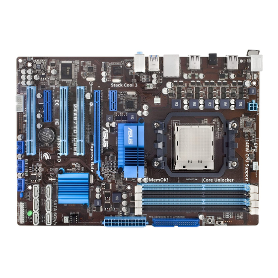
Page 17: Motherboard Layout
1.5.3 Motherboard layout 1.5.4 Layout contents Connectors/Jumpers/Slots Page ATX power connectors (24-pin EATXPWR, 4-pin ATX12V) 1-22 CPU socket AM3 CPU, Chassis and Power Fan connectors (4-pin CPU_FAN, 3-pin CHA_FAN1, 1-24 3-pin PWR_FAN) DDR3 DIMM slots Core Unlocker switch (CORE_UNLOCKER) 1-18 MemOK! switch 1-17 IDE connector (40-1 pin PRI_IDE) -
Page 18: Central Processing Unit (Cpu)
Carefully insert the CPU into the socket until it fits in place. The CPU fits only in one correct orientation. DO NOT force the CPU into the socket to prevent bending the pins and damaging the CPU! Small triangle Gold triangle ASUS M4A87TD... -
Page 19: Installing The Heatsink And Fan
When the CPU is in place, push down the socket lever to secure the CPU. The lever clicks on the side tab to indicate that it is locked. Install a CPU heatsink and fan following the instructions that came with the heatsink package. You can also refer to section 1.6.2 Installing the heatsink and fan for instructions. -
Page 20: System Memory
(DIMM) sockets. A DDR3 module has the same physical dimensions as a DDR2 DIMM but is notched differently to prevent installation on a DDR2 DIMM socket. DDR3 modules are developed for better performance with less power consumption. The figure illustrates the location of the DDR3 DIMM sockets: ASUS M4A87TD... -
Page 21: Memory Configurations
• Due to the CPU spec., AMD AM3 100 and 200 series CPUs support up to DDR3 1066MHz. With ASUS design, this motherboard can support up to DDR3 1333MHz. • When overclocking, some AMD CPU models may not support DDR3 1600 or higher frequency DIMMs. - Page 22 4GB(2 x 2GB) DS - 8-8-8 1.65 • • • OCZ3FXE1600C7LV6GK 6GB(3 x 2GB) DS - 7-7-7 1.65 • OCZ3X1600LV6GK(XMP) 6GB(3 x 2GB) DS - 8-8-8 1.65 • OCZ3X1600LV6GK(XMP) 6GB(3 x 2GB) DS - 8-8-8 1.65 • ASUS M4A87TD 1-10...
- Page 23 DDR3-1600MHz capability DIMM socket support (Optional) Chip Chip Vendor Part No. Size Timing Voltage Brand 1 DIMM 2 DIMM 4 DIMM Super Talent WB160UX6G8(XMP) 6GB(3 x 2GB) DS - • Super Talent WB160UX6G8(XMP) 6GB(3 x 2GB) DS - • EK Memory EKM324L28BP8-I16(XMP) 4GB(2 x 2GB) DS - •...
- Page 24 6GB(3 x 2GB) DS - 9-9-9-24 1.65 • • Silicon SP001GBLTU1333S01 SS NANYA NT5CB128M8AN-CG - • • Power Silicon SP001GBLTU133S02 SS S-POWER I0YT3E0 • Power Silicon SP002GBLTU133S02 DS S-POWER I0YT3E0 • • • Power UMAX E41302GP0-73BDB DS UMAX U2S24D30TP-13 • • ASUS M4A87TD 1-12...
- Page 25 Dual-channel memory configuration. • C*: Supports four modules inserted into both the blue slots and the black slots as two pairs of Dual-channel memory configuration. Visit the ASUS website for the latest QVL. Chapter 1: Product introduction 1-13...
-
Page 26: Installing A Dimm
Simultaneously press the retaining clips outward to unlock the DIMM. Remove the DIMM from the socket. Support the DIMM lightly with your fingers when pressing the retaining clips. The DIMM might get damaged when it flips out with extra force. ASUS M4A87TD 1-14... -
Page 27: Expansion Slots
Expansion slots In the future, you may need to install expansion cards. The following sub-sections describe the slots and the expansion cards that they support. Unplug the power cord before adding or removing expansion cards. Failure to do so may cause you physical injury and damage motherboard components. -
Page 28: Jumper
• Due to the chipset behavior, AC power off is required to enable C.P.R. function. You must turn off and on the power supply or unplug and plug the power cord before rebooting the system. ASUS M4A87TD 1-16... -
Page 29: Onboard Switch
If the installed DIMMs still fail to boot after the whole tuning process, the DRAM_LED lights continuously. Replace the DIMMs with ones recommended in the Memory QVL (Qualified Vendors Lists) in this user manual or on the ASUS website at www.asus.com. -
Page 30: Onboard Leds
• The system will use the last setting you have made. • If you clear the CMOS or load the BIOS setting defaults, the ASUS Core Unlocker item in the BIOS menu follows the current setting of the Core Unlocker switch. - Page 31 Core Unlocker LED The Core Unlocker LED lights when the Core Unclocker switch is turned to Enable. Chapter 1: Product introduction 1-19...
-
Page 32: Connectors
USB 2.0 (3.0) ports 1 and 2 (blue). These 4-pin Universal Serial Bus (USB) ports are available for connecting USB 2.0 (3.0) devices. (USB 3.0 only for USB3 Edition) Microphone port (pink). This port connects a microphone. ASUS M4A87TD 1-20... -
Page 33: Internal Connectors
Refer to the audio configuration table below for the function of the audio ports in 2, 4, 6, or 8-channel configuration. Audio 2, 4, 6, 8-channel configuration Headset Port 4-channel 6-channel 8-channel* 2-channel Light Blue Line In Rear Speaker Out Rear Speaker Out Rear Speaker Out Lime... - Page 34 The system may become unstable or may not boot up if the power is inadequate. • If you are uncertain about the minimum power supply requirement for your system, refer to the Recommended Power Supply Wattage Calculator at http://support.asus. com/PowerSupplyCalculator/PSCalculator.aspx?SLanguage=en-us for details. ASUS M4A87TD...
- Page 35 ® SB850 Serial ATA Serial ATA 6.0 Gb/s connectors (7-pin SATA 1-6) These connectors are for the Serial ATA 6.0 Gb/s signal cables for Serial ATA hard disk drives and optical disc drives. If you installed Serial ATA hard disk drives, you can create a RAID 0, RAID 1, RAID 5, ®...
- Page 36 • The CPU_FAN connector supports the CPU fan of maximum 2A (24 W) fan power. • Only the CPU_FAN connector support the ASUS Fan Xpert feature. • If you install two VGA cards, we recommend that you plug the rear chassis fan cable to the motherboard connector labeled CHA_FAN1 for better thermal environment.
-
Page 37: System Panel Connector
System panel connector (20-8 pin PANEL) This connector supports several chassis-mounted functions. • System power LED (2-pin PLED) This 2-pin connector is for the system power LED. Connect the chassis power LED cable to this connector. The system power LED lights up when you turn on the system power, and blinks when the system is in sleep mode. - Page 38 Never connect a 1394 cable to the USB connectors. Doing so will damage the motherboard! The USB 2.0 module is purchased separately. Digital audio connector (4-1 pin SPDIF_OUT) This connector is for an additional Sony/Philips Digital Interface (S/PDIF) ports. The S/PDIF module is purchased separately. ASUS M4A87TD 1-26...
- Page 39 Front panel audio connector (10-1 pin AAFP) This connector is for a chassis-mounted front panel audio I/O module that supports either High Definition Audio or AC`97 audio standard. Connect one end of the front panel audio I/O module cable to this connector. •...
-
Page 40: Software Support
ASUS website at www.asus.com for updates. • For detailed software instructions, see the Manual folder in the Support DVD or download the latest software manual from the ASUS website at www.asus.com. To run the Support DVD Place the Support DVD to the optical drive. The DVD automatically displays the Drivers menu if Autorun is enabled in your computer. -
Page 41: Knowing Bios
Refer to the corresponding sections for details on these utilities. Save a copy of the original motherboard BIOS file to a USB flash drive in case you need to restore the BIOS in the future. Copy the original motherboard BIOS using the ASUS Update utility. -
Page 42: Asus Update Utility
2.2.1 ASUS Update utility The ASUS Update is a utility that allows you to manage, save, and update the motherboard BIOS in Windows environment. ® • ASUS Update requires an Internet connection either through a network or an Internet Service Provider (ISP). -
Page 43: Asus Ez Flash 2 Utility
When the correct BIOS file is found, EZ Flash 2 performs the BIOS update process and automatically reboots the system when done. • Only a USB flash disk with FAT 32/16 format and single partition can support the ASUS EZ Flash 2 utility. -
Page 44: Asus Crashfree Bios 3 Utility
The BIOS file in the motherboard support DVD may be older than the BIOS file published on the ASUS official website. If you want to use the newer BIOS file, download the file at support.asus.com and save it to a USB flash drive. -
Page 45: Asus Bios Updater
2.2.4 ASUS BIOS Updater The ASUS BIOS Updater allows you to update BIOS in DOS environment. This utility also allows you to copy the current BIOS file that you can use as a backup when the BIOS fails or gets corrupted during the updating process. -
Page 46: Backing Up The Current Bios
ASUSTek BIOS Updater for DOS V1.00b [09/06/22] FLASH TYPE: MXIC 25L1605A Current ROM Update ROM BOARD: M4A87TD BOARD: Unknown VER: 0206 VER: Unknown DATE: 02/09/2010 DATE: Unknown PATH: BIOS backup is done! Press any key to continue. Note Saving BIOS: ASUS M4A87TD... -
Page 47: Updating The Bios File
Updating the BIOS file To update the BIOS file using BIOS Updater At the FreeDOS prompt, type bupdater /pc /g and press <Enter>. D:\>bupdater /pc /g The BIOS Updater screen appears as below. ASUSTek BIOS Updater for DOS V1.00b [09/06/22] FLASH TYPE: MXIC 25L1605A Current ROM... -
Page 48: Bios Setup Program
• The BIOS setup screens shown in this section are for reference purposes only, and may not exactly match what you see on your screen. • Visit the ASUS website at www.asus.com to download the latest BIOS file for this motherboard. -
Page 49: Bios Menu Screen
• The BIOS setup screens shown in this chapter are for reference purposes only, and may not exactly match what you see on your screen. • Visit the ASUS website at www.asus.com to download the latest BIOS information. Chapter 2: BIOS setup... -
Page 50: Navigation Keys
Scroll bar fit on the screen. Press the <Up> / <Down> Pop-up window arrow keys or <Page Up> / <Page Down> keys to display the other items on the screen. 2-10 ASUS M4A87TD... -
Page 51: Main Menu
Main menu When you enter the BIOS Setup program, the Main menu screen appears, giving you an overview of the basic system information. Refer to section 2.3.1 BIOS menu screen for information on the menu screen items and how to navigate through them. BIOS SETUP UTILITY Main Ai Tweaker... -
Page 52: Storage Configuration
<Enter> to display the submenu. OnChip SATA Channel [Enabled] [Enabled] Enables the onboard channel SATA port. [Disabled] Disables the onboard channel SATA port. The following two items appear only when you set the OnChip SATA Channel item to [Enabled]. 2-12 ASUS M4A87TD... -
Page 53: System Information
SATA Port1–Port4 [IDE] Allows you to set the SATA configuration. [IDE] Set to [IDE] when you want to use the Serial ATA hard disk drives as Parallel ATA physical storage devices. [RAID] Set to [RAID] when you want to create a RAID configuration from the SATA hard disk drives. -
Page 54: Ai Tweaker Menu
OC Tuner utility automatically overclocks the frequency and voltage of the CPU and DRAM. Press <Enter> to start auto tuning. It takes around five minutes, and the system will reboot for several times until auto tuning is completed. 2-14 ASUS M4A87TD... -
Page 55: Ai Overclock Tuner
2.5.3 Ai Overclock Tuner [Auto] Allows you to select the CPU overclocking options to achieve the desired CPU internal frequency. Select any of these preset overclocking configuration options: Manual Allows you to individually set overclocking parameters. Auto Loads the optimal settings for the system. Allows you to select a DRAM O.C. -
Page 56: Cpu/Nb Frequency
DRAM READ to WRITE Delay [Auto] Configuration options: [Auto] [3 CLK] – [17 CLK] [3 CLK] – [17 CLK] DRAM WRITE to READ Delay(DD) [Auto] Configuration options: [Auto] [2 CLK] – [10 CLK] [2 CLK] – [10 CLK] 2-16 ASUS M4A87TD... -
Page 57: Dram Driving Configuration
DRAM WRITE to READ Delay(SD) [Auto] Configuration options: [Auto] [4 CLK] [5 CLK] [6 CLK] [7 CLK] [4 CLK] [5 CLK] [6 CLK] [7 CLK] DRAM WRITE to WRITE Timing [Auto] Configuration options: [Auto] [3 CLK] – [10 CLK] DRAM READ to READ Timing [Auto] Configuration options: [Auto] [3 CLK] –... -
Page 58: Dram Voltage
[Auto] Automatic configuration. [Disabled] Enhances the CPU overclocking ability. [Enabled] Sets to [Enabled] for EMI control. 2.5.17 PCIE Spread Spectrum [Auto] [Auto] Automatic configuration. [Disabled] Enhances the PCIE overclocking ability. [Enabled] Sets to [Enabled] for EMI control. 2-18 ASUS M4A87TD... -
Page 59: Advanced Menu
[Enabled] Enables the AMD Cool’n’Quiet function. [Disabled] Disables this function. ASUS Core Unlocker [Disabled] [Enabled] Enables the ASUS Core Unlocker to get the full computing power of the processor. [Disabled] Disables this function. C1E Support [Enabled] [Enabled] Enables the C1E support function. This item should be enabled in order to enable the Enhanced Halt Sate. -
Page 60: Chipset
Onboard Devices Configuration HD Audio Azalia Device [Enabled] Allows you to enable or disable the HD Audio controller. Configuration options: [Disabled] [Enabled] The following item appear only when you set the HD Audio Azalia Device item to [Enabled]. 2-20 ASUS M4A87TD... -
Page 61: Usb Configuration
Azalia Front Panel [HD] Allows you to set the front panel audio connector (AAFP) mode to legacy AC’97 or high-definition audio depending on the audio standard that the front panel audio module supports. [AC 97] Sets the front panel audio connector (AAFP) mode to legacy AC’97 [HD] Sets the front panel audio connector (AAFP) mode to high definition audio. -
Page 62: Pcipnp
When set to [Yes] and if you install a Plug and Play operating system, the operating system configures the Plug and Play devices not required for boot. [No] When set to [No], BIOS configures all the devices in the system. 2-22 ASUS M4A87TD... -
Page 63: Power Menu
Power menu The Power menu items allow you to change the settings for the Advanced Configuration and Power Interface (ACPI) and the Advanced Power Management (APM). Select an item then press <Enter> to display the configuration options. BIOS SETUP UTILITY Main Ai Tweaker Advanced... -
Page 64: Apm Configuration
2.7.6 Hardware Monitor CPU/MB Temperature [xxxºC/xxxºF] The onboard hardware monitor automatically detects and displays the motherboard and CPU temperatures. Select [Ignored] if you do not wish to display the detected temperatures. 2-24 ASUS M4A87TD... - Page 65 CPU Fan / Power Fan / Chassis Fan Speed [xxxxRPM] or [Ignored] The onboard hardware monitor automatically detects and displays the CPU and chassis fan speeds in rotations per minute (RPM). If the fan is not connected to the motherboard, the field shows N/A.
-
Page 66: Boot Menu
This allows you to enable or disable the full screen logo display feature. Configuration options: [Disabled] [Enabled] Set this item to [Enabled] to use the ASUS MyLogo 2™ feature. AddOn ROM Display Mode [Force BIOS] Sets the display mode for option ROM. Configuration options: [Force BIOS] [Keep Current] Bootup Num-Lock [On] Allows you to select the power-on state for the NumLock. -
Page 67: Security
2.8.3 Security The Security menu items allow you to change the system security settings. Select an item then press <Enter> to display the configuration options. Change Supervisor Password Select this item to set or change the supervisor password. The Supervisor Password item on top of the screen shows the default Not Installed. -
Page 68: Tools Menu
(C)Copyright 1985-2009, American Megatrends, Inc. 2.9.1 ASUS EZ Flash 2 Allows you to run ASUS EZ Flash 2. When you press <OK>, a confirmation message appears. Use the left/right arrow key to select between [Yes] or [No], then press <OK> to confirm your choice. -
Page 69: Asus O.c. Profile
2.9.3 ASUS O.C. Profile This item allows you to store or load multiple BIOS settings. Add Your CMOS Profile. Allows you to save the current BIOS file to the BIOS Flash. In the Name sub-item, type your profile name and press <Enter>, and then choose a profile number to save your CMOS settings in the Save To sub-item. -
Page 70: Exit Menu
When you select this option or if you press <F5>, a confirmation window appears. Select OK to load default values. Select Exit & Save Changes or make other changes before saving the values to the non-volatile RAM. 2-30 ASUS M4A87TD... -
Page 71: Asus Contact Information
+1-812-282-3777 +1-510-608-4555 Web site usa.asus.com Technical Support Telephone +1-812-282-2787 Support fax +1-812-284-0883 Online support support.asus.com ASUS COMPUTER GmbH (Germany and Austria) Address Harkort Str. 21-23, D-40880 Ratingen, Germany +49-2102-959911 Web site www.asus.de Online contact www.asus.de/sales Technical Support Telephone +49-1805-010923* Support Fax...