Table of Contents
Advertisement
Advertisement
Table of Contents

Related Manuals for Asus M2N68-AM SE


Summary of Contents for Asus M2N68-AM SE
- Page 1 M2N68-AM SE...
- Page 2 Product warranty or service will not be extended if: (1) the product is repaired, modified or altered, unless such repair, modification of alteration is authorized in writing by ASUS; or (2) the serial number of the product is defaced or missing.
-
Page 3: Table Of Contents
Contents Notices ......................v Safety information ..................vi About this guide ..................vi M2N68-AM SE specifications summary ..........viii Chapter 1: Product introduction Before you proceed ..............1-1 Motherboard overview ..............1-2 1.2.1 Motherboard layout ............1-2 1.2.2 Layout contents ............... 1-2 Central Processing Unit (CPU) ........... - Page 4 Contents BIOS setup program ..............2-4 Main menu ..................2-4 2.3.1 System Time ..............2-4 2.3.2 System Date ..............2-4 2.3.3 IDE Configuration ............2-5 2.3.4 Primary IDE Master/Slave ..........2-5 2.3.5 SATA 1-2 ................. 2-6 2.3.6 System Information ............2-6 Advanced menu ................
-
Page 5: Notices
Notices Federal Communications Commission Statement This device complies with Part 15 of the FCC Rules. Operation is subject to the following two conditions: • This device may not cause harmful interference, and • This device must accept any interference received including interference that may cause undesired operation. -
Page 6: Safety Information
Safety information Electrical safety • To prevent electric shock hazard, disconnect the power cable from the electric outlet before relocating the system. • When adding or removing devices to or from the system, ensure that the power cables for the devices are unplugged before the signal cables are connected. If possible, disconnect all power cables from the existing system before you add a device. -
Page 7: Conventions Used In This Guide
Refer to the following sources for additional information and for product and software updates. ASUS websites The ASUS website provides updated information on ASUS hardware and software products. Optional documentation Your product package may include optional documentation, such as warranty flyers, that may have been added by your dealer. -
Page 8: M2N68-Am Se Specifications Summary
* Due to AM2+ CPU limitation, only one DDR2 1066 is supported per channel. Refer to www.asus.com for the AM2+ CPU models. ** Refer to www.asus.com for the latest Memory QVL (Qualified Vendors List). *** When you install a total memory of 4GB or more,... - Page 9 1 x 24-pin EATX power connector 1 x 4-pin ATX 12V power connector BIOS 8Mb Flash ROM, AMI BIOS, PnP, DMI2.0, WfM2.0, ACPI2.0, SM BIOS 2.5, ASUS EZ Flash2 Accessories 1 x Serial ATA cable 1 x UltraDMA 133/100/66 cable...
-
Page 10: Chapter 1: Product Introduction
Chapter 1 Product introduction Thank you for buying an ASUS M2N68-AM SE motherboard! ® Before you start installing the motherboard, and hardware devices on it, check the items in your motherboard package. Refer to page ix for the list of accessories. -
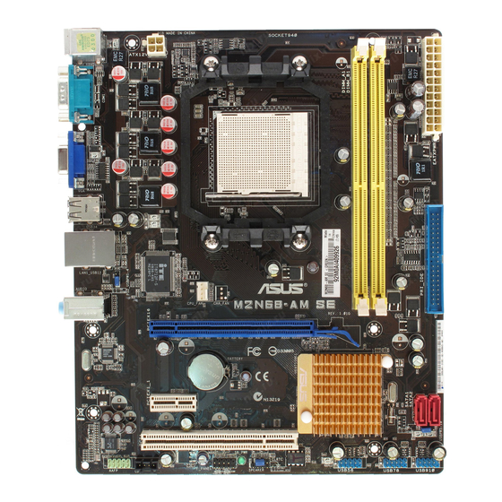
Page 11: Motherboard Overview
13. Front panel audio connector (10-1 pin AAFP) 1-14 Keyboard/mouse power (3-pin PS2_USBPW 1-4) 14. AM2 CPU Socket USB connectors (10-1 pin USB56, USB 78, USB910) 1-12 15. DDR2 DIMM slots Clear RTC RAM (3-pin CLRTC) 16. PCIe x16/PCIe x1/PCI slot ASUS M2N68-AM SE... -
Page 12: Central Processing Unit (Cpu)
240-pin footprint compared to the 184-pin DDR DIMM. DDR2 DIMMs are notched differently to prevent installation on a DDR DIMM socket. The figure illustrates the location of the DDR2 DIMM sockets: M2N68-AM SE M2N68-AM SE 240-pin DDR2 DIMM sockets Channel Sockets Channel A... -
Page 13: Memory Configurations
• This motherboard does not support DIMMs made up of 256 megabits (Mb) chips or less. This motherboard supports up to 4GB memory modules on Windows XP Professional x64 and Vista x64 editions. You may install a maximum of 2GB DIMMs on each slot. M2N68-AM SE Motherboard Qualified Vendors Lists (QVL) DDR2-533MHz capability DIMM support... - Page 14 DDR2-667MHz capability DIMM support Size Vendor Model Brand SS/DS Component 512MB Kingmax KLCC28F-A8KB5 Kingmax KKEA88B4LAUG-29DX • • Kingmax KLCD48F-A8KB5 Kingmax KKEA88B4LAUG-29DX • • 512MB Apacer 78.91092.420 Elpida E5108AE-6E-E • • 512MB Apacer AU512E667C5KBGC Apacer AM4B5708MIJS7E0627B • • 512MB Apacer AU512E667C5KBGC Apacer AM4B5708GQJS7E06332F •...
- Page 15 • A*: Supports one module inserted into either slot as the single-channel memory configuration. • B*: Supports one pair of modules inserted into both the yellow slots as one pair of dual-channel memory configuration. Visit the ASUS website at www.asus.com for the latest QVL. ASUS M2N68-AM SE...
-
Page 16: Expansion Slots
Expansion slots In the future, you may need to install expansion cards. The following sub-sections describe the slots and the expansion cards that they support. Unplug the power cord before adding or removing expansion cards. Failure to do so may cause you physical injury and damage motherboard components. -
Page 17: Jumpers
DRAM in slow refresh, power supply in reduced power mode). The USBPW5-10 jumper is for the internal USB connectors that you can connect to additional USB ports. USBPW5-10 M2N68-AM SE +5VSB (Default) M2N68-AM SE USB Device Wake Up ASUS M2N68-AM SE... -
Page 18: Connectors
PS2_USBPW1-4 jumper is for the rear USB ports. PS2_USBPW1-4 +5VSB M2N68-AM SE (Default) M2N68-AM SE Keyboard/mouse power Connectors 1.7.1 Rear panel ports PS/2 Mouse port. This port is for a PS/2 mouse. LAN (RJ-45) port. This port allows 10/100 PHY connection to a Local Area Network (LAN) through a network hub. -
Page 19: Internal Connectors
1.5Gb/s specification. The data transfer rate of the Serial ATA 3Gb/s is faster than the standard parallel ATA with 133MB/s (Ultra DMA133). SATA1 SATA2 M2N68-AM SE RSATA_TXN1 RSATA_TXN2 RSATA_TXP1 RSATA_TXP2 RSATA_RXN1 RSATA_RXN2 RSATA_RXP1 RSATA_RXP2 M2N68-AM SE SATA connectors Install the Windows XP Service Pack 1 before using Serial ATA. ® ASUS M2N68-AM SE 1-10... - Page 20 Optical drive audio in connector (4-pin CD) This connector allows you to receive stereo audio input from sound sources such as a CD-ROM, TV tuner, or MPEG card. M2N68-AM SE M2N68-AM SE Internal audio connector 1-11 Chapter 1: Product introduction...
- Page 21 DO NOT forget to connect the CPU fan cable to the CPU fan connector. Insufficient air flow inside the system may damage the motherboard components. It is not a jumper! DO NOT place a jumper cap on the CPU fan connector. Only the CPU fan supports the ASUS Q-Fan feature. CPU_FAN CPU FAN PWM...
-
Page 22: Atx Power Connectors
The system may become unstable or may not boot up if the power is inadequate. • If you are uncertain about the minimum power supply requirement for your system, refer to the Recommended Power Supply Wattage Calculator at http://support.asus. com/PowerSupplyCalculator/PSCalculator.aspx?SLanguage=en-us for details. Speaker connector (4- pin SPEAKER) This 4-pin connector is for the chassis-mounted system warning speaker. -
Page 23: System Panel Connector (10-1 Pin F_Panel)
M2N68-AM SE Analog front panel connector If you want to connect a high-definition front panel audio module to this connector, ensure that the Front Panel Select item in the BIOS is set to [HD Audio]. If you want to connect an AC97 front panel audio module to this connector, set the item to [AC97]. -
Page 24: Software Support
Autorun function is enabled on your computer. The contents of the Support DVD are subject to change at any time without notice. Visit the ASUS website at www.asus.com for updates. Click an icon to display Support DVD/... -
Page 25: Asus Express Gate
1.8.3 ASUS Express Gate ASUS Express Gate is an instant-on environment that gives you quick access to the Internet. Five seconds after bootup, you can instantly surf the Internet, use Skype or other Express Gate applications. Installing ASUS Express Gate •... - Page 26 The Splash Screen Express Gate’s splash screen appears within a few seconds after bootup. From here, immediately start surfing the Internet, chat on Skype, enter the OS or BIOS, or power off your computer. If you do not make any selection, Express Gate automatically closes and boots to your OS after some time.
-
Page 27: Using The Configuration Panel
SSID. • The number of the LAN ports may differ from motherboards. • You can connect the LAN cable to any RJ-45 port, and Express Gate automatically uses the available port. ASUS M2N68-AM SE 1-18... - Page 28 • Environment Settings: This function allows you to clear the Express Gate settings and any information saved by the web browser such as bookmarks, cookies, and history. The user data is restored to the original default configurations. After you click Restore System, a confirmation dialog box appears. If you click Yes in the confirmation dialog box, your system immediately restarts.
- Page 29 Launches File Manager which allows you to access files on a USB drive. If a USB device is detected, the icon contains a green arrow. ASUS Express Gate supports file uploading from SATA HDDs, ODDs, and USB drives. It supports file downloading to USB drives only.
- Page 30 Open Network. Network Make the proper network configurations. Each network interface is enabled immediately after you tick the Enable checkbox. • If you use a network cable connected to a home router that is connected to your DSL/ cable modem, enable all the LAN ports. Express Gate automatically uses the available port.
- Page 31 Shows user- created image albums Image control bar ASUS Express Gate supports HDDs connected to motherboard chipset-controlled onboard SATA ports only. All onboard extended SATA ports and external SATA ports are NOT supported. ASUS M2N68-AM SE 1-22...
- Page 32 The InstallShield Wizard for Express Gate appears. Click Next to continue. Follow the onscreen instructions to complete the updating process. Download the latest Express Gate version from the ASUS website at www.asus.com. Repairing Express Gate In case Express Gate does not start normally, reinstall the software or use the repair utility to repair Express Gate.
-
Page 33: Chapter 2: Bios Information
BIOS in the future. Copy the original motherboard BIOS using the ASUS Update utility. 2.1.1 ASUS Update utility The ASUS Update is a utility that allows you to manage, save, and update the motherboard BIOS in Windows environment. ®... -
Page 34: Asus Ez Flash 2 Utility
When the correct BIOS file is found, EZ Flash 2 performs the BIOS updating process and automatically reboots the system when done. • Only a USB flash disk with FAT 32/16 format and single partition supports the ASUS EZ Flash 2 utility. -
Page 35: Asus Crashfree Bios 3 Utility
2.1.3 ASUS CrashFree BIOS 3 utility The ASUS CrashFree BIOS 3 utility is an auto recovery tool that allows you to restore the BIOS file when it fails or gets corrupted during the updating process. You can update a corrupted BIOS file using the motherboard Support DVD or a USB flash disk that contains the updated BIOS file. -
Page 36: Bios Setup Program
• The BIOS setup screens in this section are for reference only. They may not exactly match what you see on your screen. • Visit the ASUS website at www.asus.com to download the latest BIOS file for this motherboard. Main menu When you enter the BIOS Setup program, the Main menu screen appears, giving you an overview of the basic system information. -
Page 37: Ide Configuration
2.3.3 IDE Configuration The items in this menu allow you to set or change the configurations for the IDE devices installed in the system. Select an item then press <Enter> if you want to configure the item. Onboard IDE Controller [Enabled] Enables or disables the onboard IDE controller. -
Page 38: Sata 1-2
This menu gives you an overview of the general system specifications. The BIOS automatically detects the items in this menu. AMI BIOS Displays the auto-detected BIOS information Processor Displays the auto-detected CPU specification System Memory Displays the auto-detected system memory ASUS M2N68-AM SE... -
Page 39: Advanced Menu
Advanced menu The Advanced menu items allow you to change the settings for the CPU and other system devices. Take caution when changing the settings of the Advanced menu items. Incorrect field values can cause the system to malfunction. BIOS SETUP UTILITY Main Advanced Power Boot... - Page 40 Configuration options: [Auto] [0 CLK] ~ [3 CLK] tWTR [Auto] Configuration options: [Auto] [1 CLK] [2 CLK] [3 CLK] [Auto] [1 CLK] [2 CLK] [3 CLK] tWRWR [Auto] Configuration options: [Auto] [1 CLK] [2 CLK] [3 CLK] ASUS M2N68-AM SE...
-
Page 41: Cpu Configuration
tRDRD [Auto] Configuration options: [Auto] [2 CLK] ~ [5 CLK] tRFCO [Auto] Configuration options: [Auto] [75ns] [105ns] [127.5ns] [195ns] [327.5ns] tRFC1 [Auto] Configuration options: [Auto] [75ns] [105ns] [127.5ns] [195ns] [327.5ns] tRFC2 [Auto] Configuration options: [Auto] [75ns] [105ns] [127.5ns] [195ns] [327.5ns] tRFC3 [Auto] Configuration options: [Auto] [75ns] [105ns] [127.5ns] [195ns] [327.5ns] Memory Voltage [Auto]... -
Page 42: Chipset
Sets the iGPU frame buffer detect. Configuration options: [Auto] [Disabled] AZALIA AUDIO [Enabled] Allows you to enable or disable the HD audio mode. Configuration options: [Disabled] [Enabled] Front Panel Select [HD Audio] Allows you to set the HD audio mode. Configuration options: [AC97] [HD Audio] 2-10 ASUS M2N68-AM SE... -
Page 43: Onboard Devices Configuration
Onboard LAN [Auto] Allows you to set or disable the Onboard LAN. Configuration options: [Auto] [Disabled] Onboard LAN Boot ROM [Disabled] Allows you to enable or disable the Onboard LAN boot ROM. Configuration options: [Enabled] [Disabled] SouthBridge ACPI HPET TABLE [Enabled] Allows you to enable or disable SouthBridge ACPI HPET TABLE. -
Page 44: Usb Configuration
(default). In S3 sleep state, the system appears to be off and consumes less power than in the S1 state. When signaled by a wake-up device or event, the system resumes to its working state exactly where it was left off. [Auto] - Detected by OS. 2-12 ASUS M2N68-AM SE... -
Page 45: Acpi Version Features
The onboard hardware monitor automatically detects the voltage output through the onboard voltage regulators. Smart Q-Fan Function [Disabled] Allows you to enable or disable the ASUS Q-Fan feature that smartly adjusts the CPU fan speeds for more efficient system operation. Configuration options: [Disabled] [Enabled] Chapter 2: BIOS information... -
Page 46: Boot Menu
This allows you to enable or disable the full screen logo display feature. Configuration options: [Disabled] [Enabled] Set this item to [Enabled] to use the ASUS MyLogo 2™ feature. AddOn ROM Display Mode [Force BIOS] Sets the display mode for option ROM. Configuration options: [Force BIOS] [Keep Current] Bootup Num-Lock [On] Allows you to select the power-on state for the NumLock. -
Page 47: Security
Hit ‘DEL’ Message Display [Enabled] When set to Enabled, the system displays the message Press DEL to run Setup during POST. Configuration options: [Disabled] [Enabled] Interrupt 19 Capture [Disabled] When set to [Enabled], this function allows the option ROMs to trap Interrupt 19. Configuration options: [Disabled] [Enabled] 2.6.3 Security... -
Page 48: Tools Menu
1.NTFS format ASUS EZ Flash 2 Allows you to run ASUS EZ Flash 2. When you press <OK>, a confirmation message appears. Use the left/right arrow key to select between [Yes] or [No], then press <OK> to confirm your choice.