Advertisement
Quick Links
Advertisement

Related Manuals for Pioneer ND-BC5


Summary of Contents for Pioneer ND-BC5
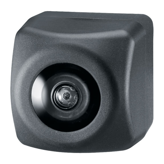
- Page 1 UNIVERSAL REAR-VIEW CAMERA CAMERA DE RECUL UNIVERSELLE Owner’s Manual Mode d’emploi ND-BC5...
- Page 2 This device complies with part 15 of the FCC Handling the cord on this product or cords associated Rules. with accessories sold with the product may expose Operation is subject to the following two you to chemicals listed on proposition 65 known to conditions: the State of California and other governmental enti- (1) This device may not cause harmful interference,...
- Page 3 Parts supplied • Install the unit near the center of the car. • Locate in the position you want to install the rear view camera. Adjust the angle of the rear view �� Rear view camera × 1 �� RCA power supply cable × 1 camera, and install so that the camera doesn’t ��...
- Page 4 �� Rear view camera × 1 �� RCA power supply cable × 1 �� Power supply unit × 1 �� Hexagon wrench × 1 �� Hook and loop fastener �� Hook and loop fastener (soft type) × 1 (hard type) × 1 ��...
- Page 5 Be sure not to hide any part of the char- Mark acters on the license plate when attaching the camera. Bottom Make sure to install the rear view camera so that the mark is located on top of the camera. Fig.5 Fig.
- Page 6 Power supply unit Rear view Power supply Rear view camera Clamps RCA power supply cable camera unit connector connector Product with a video input jack (Hideaway Rear view camera unit etc.) RCA power supply cable 3 m (9 ft. 10 in.) RCA pin Fuse (1A) 3 m (9 ft.
- Page 7 Waterproof pad Clamps Pull out from here Hinge Harness cover Rear view camera Make a U-shaped loop in the lead outside the rubber packing to prevent rainwa- Hatch ter from flowing along the Rubber packing lead into the interior of the vehicle.
- Page 8 Accessory power supply • This unit is for vehicles with a 12-volt battery and nega- To electric terminal controlled by ignition tive grounding. Before installing it in a recreational vehi- switch (12 V DC) ON/OFF. cle, truck, or bus, check the battery voltage. •...
- Page 9 Power source ........... 14.4 V DC Dimensions (10.8 V to 15.1 V allowable) Camera unit ..23 (W) mm × 23 (H) mm × 24 (D) mm Grounding system ......Negative type ... 7/8 (W) in. × 7/8 (H) in. × 1 (D) in. Max.
- Page 10 340 Ferrier Street, Unit 2, Markham, Ontario L3R 2Z5, Canada TEL: 1 877 283 5901 TEL: 905 479 4411 PIONEER ELECTRONICS DE MEXICO, S.A. de C.V. Blvd. Manuel Avila Camacho 138 10 piso Col. Lomas de Chapultepec, Mexico, D.F. 11000 TEL: 55 9178 4270 ©...