Table of Contents
Advertisement
Quick Links
Liquid Crystal Projector
CP-X990W/CP-X995W
USER'S MANUAL
Please read this user's manual thoroughly to ensure correct usage through understanding.
BEDIENUNGSANLEITUNG
Bitte lessen Sie diese Bedienungsanleitung zugunsten der korrekten Bedienung
aufmerksam.
MANUEL D'UTILISATION
Nous vous recommandons de lire attentivement ce manuel pour bien assimiler le
fonctionnement de l'appareil.
MANUALE D'ISTRUZIONI
Vi preghiamo voler leggere attentamente il manuale d'sitruzioni in modo tale da poter
comprendere quanto riportato ai fini di un corretto utilizzo del proiettore.
MANUAL DE USUARIO
Lea cuidadosamente este manual del usuario para poder utilizar corretamente el
producto.
GEBRUIKSAANWIJZING
Lees voor het qebruik alstublieft deze handleiding aandachtig door, om volledig profijt te
hebben van de uitgebreide mogelijkheden.
BRUKERHÅNDBOK
Vennligst les denne bruksanvisningen grundig for å være garantert driftssikker bruk.
INSTRUÇÕES DO PROPRIETÁRIO
Para assegurar o uso correto do equipamento, por favor leia atentamente este manual do
usuário.
TECHNICAL
REGULATORY NOTICES
Advertisement
Table of Contents

Related Manuals for Hitachi CP-X995J


Summary of Contents for Hitachi CP-X995J
- Page 1 Liquid Crystal Projector CP-X990W/CP-X995W USER'S MANUAL Please read this user's manual thoroughly to ensure correct usage through understanding. BEDIENUNGSANLEITUNG Bitte lessen Sie diese Bedienungsanleitung zugunsten der korrekten Bedienung aufmerksam. MANUEL D'UTILISATION Nous vous recommandons de lire attentivement ce manuel pour bien assimiler le fonctionnement de l'appareil.
-
Page 2: Table Of Contents
Liquid Crystal Projector USER'S MANUAL USER'S MANUAL Thank you for purchasing this liquid crystal projector. WARNING • Please read the accompanying manual “SAFETY INSTRUCTIONS” and this “USER'S MANUAL” thoroughly to ensure correct usage through understanding. After reading, store this instruction manual in a safe place for future reference. -
Page 3: Features
FEATURES FEATURES This liquid crystal projector is used to project various computer signals as well as NTSC / PAL / SECAM video signals onto a screen. Little space is required for installation and large images can easily be realized. Outstanding Brightness The UHB lamp and high-efficiency optical system assure a high level of brightness. -
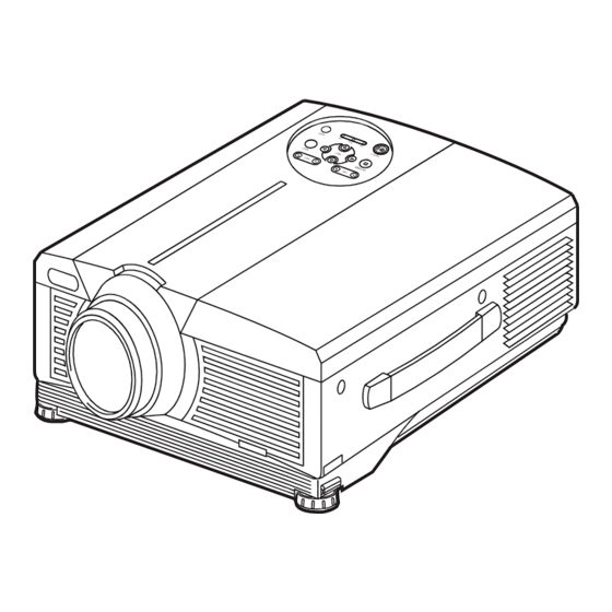
Page 4: Part Names
Part Names ZOOM Button FOCUS Button ZOOM FOCUS KEYSTONE Button INPUT Button KEYSTONE INPUT MENU STANDBY/ON Button MENU Button STANDBY/ON RESET LAMP POWER TEMP LAMP Indicator RESET Button POWER Indicator TEMP Indicator Control Panel (Refer to P.9 "OPERATIONS") Remote Control Sensor Control Panel Lens Ventilation Openings... - Page 5 Part Names (continued) BLANK Button STANDBY/ON Button LASER Button VIDEO Button RGB Button Disk Pad MOUSE / RIGHT Button Used to operate the Used to click the right mouse shift function and mouse button. left click function. KEYSTONE Button AUTO Button RESET Button MENU Button Used to click the right...
-
Page 6: Loading The Batteries
Loading the Batteries Install the AA batteries into the remote control transmitter. 1. Remove the battery cover. Push the knob while lifting up the battery cover. 2. Load the batteries. Make sure the plus and minus poles are correctly oriented. 3. -
Page 7: Installation
INSTALLATION INSTALLATION Installation of the Projector and Screen Refer to the drawing and table below for determining the screen size and projection distance. The projection distances shown in the table below Screen are for full size (1024 x 768 dots). a: Distance from the projector to the screen. -
Page 8: Cabling
Cabling Refer to the table below for connecting each terminal of the projector to a device. Table 2. Cabling Function Terminal Cable RGB IN 1 Analog RGB input RGB cable with D-sub 15-pin shrink jack RGB IN 2 and inch thread screws Analog RGB output RGB OUT Digital RGB input... -
Page 9: Power Connection
Power Connection Use the correct power cord depending on the power outlet to be used. Connect the AC inlet of the projector to the power outlet firmly by the power cord. CAUTION • Be carful in handling the power Power outlet cord according to instructions of the accompanying manual "SAFETY INSTRUCTIONS"... -
Page 10: Operations
OPERATIONS OPERATIONS STANDBY/ BLANK STANDBY/ON LASER ON Button POWER Indicator STANDBY/ON Button VIDEO ZOOM button FOCUS button AUTO MENU KEYSTONE MENU SELECT POSITION RESET Power Switch FREEZE PinP MAGNIFY MUTE FOCUS button FOCUS ZOOM VOLUME Lens cap ZOOM button Power ON 1. -
Page 11: Basic Operation
Basic Operation The basic operations shown in Table 3 is performed from the supplied remote control transmitter or the projector control panel. Items indicated by (*) may be used from the control panel. Table 3 . Basic Operation Item Description Select Input Signal ( : Press the INPUT button. - Page 12 Items indicated by (*) may be used from the control panel. Table 3. Basic Operation (continued) Item Description VOLUME Volume Adjustment : Press the VOLUME button. Set/Clear Mute Mode : Press the MUTE button. No sound is heard in the MUTE MUTE mode.
-
Page 13: Setup Menu
Setup Menu SETUP INPUT IMAGE OPT. SETUP INPUT IMAGE OPT. BRIGHT BRIGHT The following adjustments and settings are possible CONTRAST CONTRAST V POSIT SHARPNESS when SETUP is selected at the top of the menu. Part COLOR H POSIT H PHASE TINT of the Setup menu differs between RGB input and H PHASE... -
Page 14: Input Menu
Input Menu SETUP INPUT IMAGE OPT. The following functions are available when INPUT is selected on the EXECUTE AUTO menu. Select an item with the buttons, and start or stop CANCEL VIDEO operation with the buttons. The function indicated (**) are VIDEO NR Progressive effective on video input mode only, not on RGB input mode, except in... -
Page 15: Image Menu
Image Menu SETUP INPUT IMAGE OPT. The following adjustments and settings are available when IMAGE is BLANK MyScreen ORIGINAL START UP selected on the menu. Select an item with the buttons, and MyScreen MIRROR P.IN P. POSIT start or stop operation with the buttons. -
Page 16: Options Menu
Options Menu SETUP INPUT IMAGE OPT. The following adjustments and settings are available when OPT. is VOLUME MENU COLOR selected on the menu. Select an item with the buttons, and LANGUAGE AUTO OFF start operation. SYNC ON G WHISPER Table 7. Options Menu Item Description ↔... -
Page 17: No Signal Menu
No Signal Menu VOLUME BLANK The same adjustments and settings are available with the Image and START UP MIRROR Options menus when the MENU button is pressed during display of the MENU COLOR LANGUAGE “NO INPUT IS DETECTED ON ***” or “SYNC IS OUT OF RANGE AUTO OFF SYNC ON G ON ***”... -
Page 18: Maintenance
MAINTENANCE MAINTENANCE Lamp HIGH VOLTAGE HIGH TEMPERATURE HIGH PRESSURE Contact your dealer before replacing the lamp. For the optional lamp, see the item “Option Parts” of the Table 12. Before replacing the lamp, switch power OFF, remove the power cord from the power outlet, and wait approximately 45 minutes until the lamp has cooled. - Page 19 Replacing the Lamp 1. Switch the projector OFF, remove the power cord from the power outlet, and wait at least 45 minutes for the unit to cool. 2. Prepare a new lamp. 3. Check that the projector has cooled sufficiently, and gently turn it upside down.
-
Page 20: Air Filters
Air Filters filter cover Cleaning Air Filters This projector uses 2 air filters. These air filters should be cleaned as described below at intervals of approximately 100 hours. 1. Switch the projector power supply OFF, and remove the power cord from the power outlet. 2. -
Page 21: Troubleshooting
TROUBLESHOOTING TROUBLESHOOTING OSD Message The messages as described below may appear on the screen at power ON. Take the appropriate measures when such messages appears. Table 9. OSD Message Message Contents The usage time of lamp will be reaching 2000 hr CHANGE THE LAMP shortly.(*2) AFTER REPLACING LAMP,... -
Page 22: Indicators Message
Indicators Message The POWER indicator, LAMP indicator, and TEMP indicator are lit and blank as follows. Take the appropriate measures. Table 10. Indicators Message POWER LAMP TEMP Contents indicator indicator indicator Lights Turns off Turns off The Standby mode has been set. orange Blinks Turns off Turns off Warming up. -
Page 23: Symptom
Symptom Before requesting repair, check in accordance with the following chart. If the situation cannot be corrected, then contact your dealer. Table 11. Symptom Symptom Possible cause Remedy Page The main power switch is not Turn on the main power switch. turned on. -
Page 24: Specifications
SPECIFICATIONS SPECIFICATIONS Table 12. Specifications Item Specification Product name Liquid crystal projector Panel size 3.3 cm (1.3 type) Liquid crystal Drive system TFT active matrix panel Pixels 786,432 pixels (1024 horizontal x 768 vertical) Lens Zoom lens F=1.7 ~ 2.3 f=49.0 ~ 64.0 mm Lamp 275 W UHB Speaker... -
Page 25: Warranty And After-Service
WARRANTY AND AFTER-SERVICE WARRANTY AND AFTER-SERVICE If a problem occurs with the equipment, first refer to the P.20 “TROUBLESHOOTING” section and run through the suggested checks. If this does not resolve the problem contact your dealer or service company. They will tell you what warranty condition is applied. ENGLISH-24 ENGLISH-24... - Page 26 TECHNICAL TECHNICAL Dimension Diagram 308.5 Unit : mm 30.5 Signal Connector Pin Assignment 1. D-sub 15-pin Shrink Connector (RGB IN 1/RGB IN 2/RGB OUT) Pin No Signal Pin No Signal Pin No Signal Video input Red RGB IN 1: SCL(DDC) Video input Green Ground RGB IN 2: -...
- Page 27 Example of computer signal Resolution Display fH (kHz) fV (Hz) Rating Signal mode H × × V mode 720 × 400 37.9 85.0 VESA TEXT Zoom in 640 × 480 31.5 59.9 VESA VGA (60Hz) Zoom in 640 × 480 35.0 66.7 Mac13"mode...
- Page 28 Initial set signals The following signals are used for the initial settings. The signal timing of some computer models may be different. In such case, refer to adjust the V.POSIT and H.POSIT of the menu. Back porch b Front porch d Back porch b Front porch d Display interval c...
- Page 29 Connection to the Mouse Control 1. PS/2, ADB or Serial Mouse (1) Turn off the projector and computer, and connect the two units with the appropriate cable. For PS/2 mouse control (for IBM and compatible), use the enclosed mouse cable. For others, consult your dealer.
- Page 30 ADB Mouse Projector Computer ( POWER ON ) CONTROL Terminal DATA Mouse jack D-sub 15-pin shrink jack Mini DIN 4-pin ! " # % & ' ! " # Serial Mouse Projector Computer CONTROL Terminal Mouse jack D-sub 15-pin shrink jack D-sub 9-pin SEL0...
- Page 31 RS-232C communication (1) Turn off the projector and computer power supplies and connect with the RS-232C cable. (2) Turn on the computer power supply and, after the computer has started up, turn on the projector power supply. Projector Computer RS-232C jack D-sub 9-pin Control jack D-sub 15-pin shrink jack...
- Page 32 Requesting projector status (Get command) (1) Send the request code Header + Command data (‘02H’+‘00H’+ type (2 bytes) +‘00H’+‘00H’) from the computer to the projector. (2) The projector returns the response code ‘1DH’+ data (2 bytes) to the computer. Changing the projector settings (Set command) (1) Send the setting code Header + Command data (‘01H’+‘00H’+ type (2 bytes) + setting code (2 bytes)) from the computer to the projector.
- Page 33 Command data chart Command data Names Operation type Header Action Type Setting code BE EF 06 00 3B D3 01 00 00 30 00 00 Orange BE EF 06 00 AB D2 01 00 00 30 01 00 Green BE EF 06 00 5B D2 01 00...
- Page 34 Command data chart Command data Names Operation type Header Action Type Setting code BE EF 06 00 7C D2 02 00 07 30 00 00 Magnify Increment BE EF 06 00 1A D2 04 00 07 30 00 00 Decrement BE EF 06 00 CB D3...
- Page 35 Command data chart Command data Names Operation type Header Action Type Setting code Normal BE EF 06 00 46 D3 01 00 02 20 00 00 Mute Mute BE EF 06 00 D6 D2 01 00 02 20 01 00 BE EF 06 00 75 D3...
- Page 36 Command data chart Command data Names Operation type Header Action Type Setting code BE EF 06 00 F1 72 02 00 01 22 00 00 Sharpness Increment BE EF 06 00 97 72 04 00 01 22 00 00 Decrement BE EF 06 00 46 73...
- Page 37 Command data chart Command data Names Operation type Header Action Type Setting code Upper left BE EF 06 00 02 23 01 00 01 23 00 00 Upper right BE EF 06 00 92 22 01 00 01 23 01 00 bottom left BE EF 06 00...
- Page 38 REGULATORY NOTICES REGULATORY NOTICES FCC Statement Warning WARNING: This equipment has been tested and found to comply with the limits for a Class B digital device, pursuant to Part 15 of the FCC Rules. These limits are designed to provide reasonable protection against harmful interference in a residential installation.
- Page 39 6740 Campobello Road, Mississauga, Ontario Spain L5N2L8, Canada Tel: +34-3-330-8652 Fax: +34-3-339-7839 Tel: +1-905-821-4545 Fax: +1-905-821-1101 Hitachi Home Electronics Asia, (S) Pte Ltd. Hitachi Home Electronics (Europe), Ltd. 16 Collyer Quay #20-00 Hitachi Tower Singapore Dukes Meadow, Millboard Road, Bourne End , 049318, Singapore...