Table of Contents
Advertisement
Quick Links
DVD AV RECEIVER
DVH-750AV
DVH-755AV
DVH-755AV
DVH-7580AV
PIONEER CORPORATION
PIONEER ELECTRONICS (USA) INC. P.O. Box 1760, Long Beach, CA 90801-1760, U.S.A.
PIONEER EUROPE NV Haven 1087, Keetberglaan 1, 9120 Melsele, Belgium
PIONEER ELECTRONICS ASIACENTRE PTE. LTD. 253 Alexandra Road, #04-01, Singapore 159936
PIONEER CORPORATION 2012
1-1, Shin-ogura, Saiwai-ku, Kawasaki-shi, Kanagawa 212-0031, Japan
DVH-750AV/XEUW5
/XERD
/XERI
/XFBR
PROVISIONAL
CRT5222P
/XEUW5
K-ZZZ DEC. 2012 Printed in Japan
Advertisement
Table of Contents

Related Manuals for Pioneer DVH-750AV/XEUW5


Summary of Contents for Pioneer DVH-750AV/XEUW5
- Page 1 PIONEER CORPORATION 1-1, Shin-ogura, Saiwai-ku, Kawasaki-shi, Kanagawa 212-0031, Japan PIONEER ELECTRONICS (USA) INC. P.O. Box 1760, Long Beach, CA 90801-1760, U.S.A. PIONEER EUROPE NV Haven 1087, Keetberglaan 1, 9120 Melsele, Belgium PIONEER ELECTRONICS ASIACENTRE PTE. LTD. 253 Alexandra Road, #04-01, Singapore 159936 PIONEER CORPORATION 2012 K-ZZZ DEC.
-
Page 2: Safety Information
The following caution label appears on your unit. Location: on top of the cover CAUTION Danger of explosion if battery is incorrectly replaced. Replaced only with the same or equivalent type recommended by the manufacture. Discord used batteries according to the manufacture's instructions. DVH-750AV/XEUW5... -
Page 3: Table Of Contents
10.5 KB PCB and AUX PCB (GUIDE PAGE) ....................58 10.6 CB ASS'Y and LB ASS'Y........................64 11. PCB CONNECTION DIAGRAM ........................66 11.1 MB ASS'Y ...............................66 11.2 SB ASS'Y ..............................70 11.3 KB PCB..............................72 11.4 AUX PCB ..............................74 11.5 CB ASS'Y..............................75 11.6 LB ASS'Y ..............................76 12. ELECTRICAL PARTS LIST...........................77 DVH-750AV/XEUW5... -
Page 4: Service Precautions
1) Turn over the Detach Panel and press RESET Button at Central Part. Without entire initialization. Microcomputer restarting (emergency resetting at function trouble) . With the reset of the pioneer. 2) Perform [Default Setting] initialization in Setting Perform product initialization except a part of items. -
Page 5: Specifications
2. SPECIFICATIONS 2.1 SPECIFICATIONS DVH-750AV/XEUW5 Backup current ........5 mA or less DVH-750AV/XEUW5... - Page 6 Frequency range: ........531 kHz to 1 602 kHz (9 kHz) ............530 kHz to 1 640 kHz (10 kHz) Usable sensitivity: ........30 dBµ (S/N: 20 dB) Note: Specifications and the design are subject to modifications without notice. DVH-750AV/XEUW5...
- Page 7 Backup current ..........5 mA or less DVH-750AV/XEUW5...
-
Page 8: Disc/Content Format
2.2 DISC/CONTENT FORMAT is a trademark of DVD Format/Logo Licensing Corporation. DVH-750AV/XEUW5... -
Page 9: Basic Items For Service
For check items concerning image and voice, please refer to the followings: Check items concerning image Check items concerning voice Block-noise Distortion Crosscut noise Noise Dot noise Low volume Distorted image (Image skip) High volume Low brightness Changes in level Too bright Pause of sound Color fading Partial discoloration DVH-750AV/XEUW5... -
Page 10: Pcb Locations
3.2 PCB LOCATIONS SB ASS'Y MB ASS'Y CB ASS'Y KB PCB LB ASS'Y A:DVH-750AV/XEUW5 B:DVH-755AV/XERD AUX PCB C:DVH-755AV/XERI D:DVH-7580AV/XFBR Unit Number : 843DM7236GRMB012-FY(A) Unit Number : 843DM7236GLMB002-FY(B) Unit Number : 843DM7236GMMB002-FY(C) Unit Number : CYW1016(D) Unit Name : MB Ass'y... -
Page 11: Jigs List
- When the Repair is Complete When the repair is complete, make the DVD mechanism ready for transportation implementing the following procedures: 1. Attach the two Transportation Screws. Now you can transport it.(See the figure below) Transportation Screws 121045000198-FY DVH-750AV/XEUW5... -
Page 12: Block Diagram
TO CB TO LBt CON2:34pin CN406:6pin TO MB TO MB CB Ass'y LB Ass'y CON1:34pin (Connector Board) (Light Board) TO KB CON201:34pin TO CB 3.0inch TFT-LCD KB Ass'y Module USB201: (Key Board) USB Connector CON1 AUX PCB AUX-IN Connector DVH-750AV/XEUW5... -
Page 13: Block Diagram
4.2 BLOCK DIAGRAM DVH-750AV/XEUW5... -
Page 14: Power Block Diagram
DVD_5V TFT_5V DVD_5V 3.3V SA1117 AP1507-ADJ -3V3 DVD_5V DVDD V_LED SA1117 TFT Driver - 1V8 TVP5150 AVDD 1.8V MAX:30mA MAX:120mA LAMP_SW Key illumination MAX:200mA +5V_M IR Receiver Rotary Encoder DVD_5V USB5V Current Term USB Connector 5V 1.5A USB-Power AP2191D DVH-750AV/XEUW5... -
Page 15: Diagnosis
Press power on key DVD Power = 5 V TFT Power On and TFT Init Starts communication with Grille microcomputer. Source keys operative Source ON Entery select mode operative Completes power-on operation. (After that, proceed to each source operation) DVH-750AV/XEUW5... -
Page 16: Error Code List
Check the speaker connection. If the Unit fails to operate or speaker message fails to disappear even after the AMP ERROR connection is incorrect; engine is switched off/on, contact your protective circuit is activated. dealer or an authorized Pioneer Service Station for assistance. DVH-750AV/XEUW5... -
Page 17: Connector Function Description
1: FR- 11: RL+ 2: FL+ 12: GND 3: FR+ 13: RL- 4: FL- 14: LO-FL 5: RR+ 15: ACCIN 6: ILLU_IN 16: LO-FR 7: RR- 17: GND 8: ANT 18: GND 9: T_MUTE 19: LO/SUB-RR 10: +B 20: LO/SUB-RL DVH-750AV/XEUW5... -
Page 18: Service Mode
6. SERVICE MODE DVH-750AV/XEUW5... -
Page 19: Disassembly
Remove the screw and then remove the Top Cover. Top Cover Fig.1 Removing the DVD Mechanism Module (Fig.2) Remove the two screws. Remove the two screws. Disconnect the two connectors and then remove the DVD Mechanism Module. DVD Mechanism Module Fig.2 DVH-750AV/XEUW5... - Page 20 Remove the four screws and then remove the Heat Sink. Heat Sink Remove the screw. Remove the solder at three locations indicated and then straighten the tabs. Remove the two screws and then remove the MB Ass’y. MB Ass’y Fig.4 DVH-750AV/XEUW5...
- Page 21 How to eject the stuck disc (Procedure 1: Rotating the roller) Remove the screws. Remove the top and the bottom cover. Remove the screws. Remove the DVD mechanism module. Rotate the gear upward. Then, the disc will be ejected. DVH-750AV/XEUW5...
- Page 22 How to eject the stuck disc (Procedure 2: Removing the top cover) Remove the screws. Remove the top and the bottom cover of the product. Remove the screws. Remove the DVD mechanism module. Remove the screws. Remove the dustproof cover. Remove the screws. Left side Right side DVH-750AV/XEUW5...
- Page 23 Remove the top cover of the DVD mechanism. Lift up the clamp holder, and remove the disc. DVH-750AV/XEUW5...
- Page 24 Removing the lever located at the reverse side of DVD mechanism's top cover Remove the top cover according to "How to eject the stuck disc (Procedure 2: Removing the top cover)" on the page 21. Remove the one screw. Remove the six hooks. Remove the black lever holder. Remove the lever. DVH-750AV/XEUW5...
-
Page 25: Each Setting And Adjustment
8. EACH SETTING AND ADJUSTMENT There is no information to be shown in this chapter. DVH-750AV/XEUW5... -
Page 26: Exploded Views And Parts List
Screw adjacent to mark on the product are used for disassembly. For the applying amount of lubricants or glue, follow the instructions in this manual. (In the case of no amount instructions,apply as you think it appropriate.) 9.1 PACKING UW5, RD, RI RD, RI UW5, BR DVH-750AV/XEUW5... - Page 27 22-5 Service Network See Contrast table (2) Pulp Foam 127015000103-FY Polyethylene Bag See Contrast table (2) (2) CONTRAST TABLE DVH-750AV/XEUW5, DVH-755AV/XERD, DVH-755AV/XERI and DVH-7580AV/XFBR are constructed the same except for the following: Mark Description DVH-750AV/XEUW5 DVH-755AV/XERD DVH-755AV/XERI DVH-7580AV/XFBR Detach Panel (Ass'y)
-
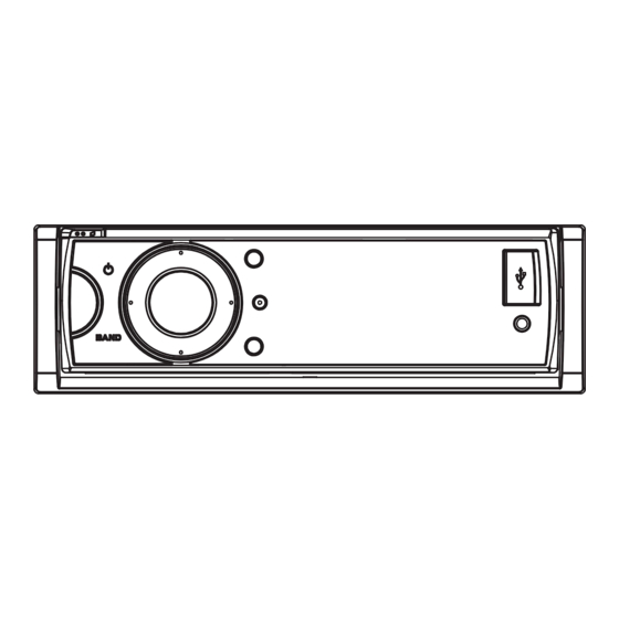
Page 28: Exterior(1)
9.2 EXTERIOR(1) UW5, RD, RI DVH-750AV/XEUW5... - Page 29 Button (SEL/ESC) 141230003896028-FY Slide Block R 14129080071400-FY See Contrast table (2) Spring L/R 121035000136-FY (2) CONTRAST TABLE DVH-750AV/XEUW5, DVH-755AV/XERD, DVH-755AV/XERI and DVH-7580AV/XFBR are constructed the same except for the following: Mark Description DVH-750AV/XEUW5 DVH-755AV/XERD DVH-755AV/XERI DVH-7580AV/XFBR Detach Panel (Ass'y) 843DM7236GLKB012-FY 843DM7236GLKB002-FY 843DM7236GLKB002-FY CXE6185...
-
Page 30: Exterior(2)(Uw5,Rd,Ri)
9.3 EXTERIOR(2)(UW5,RD,RI) DVH-750AV/XEUW5... - Page 31 141230301924018-FY Lever 121290222257-FY Sheet 121490000117-FY Heat Silica Gel 121490000464-FY Button Cover 141000001855-FY (2) CONTRAST TABLE DVH-750AV/XEUW5, DVH-755AV/XERD and DVH-755AV/XERI are constructed the same except for the following: Mark Description DVH-750AV/XEUW5 DVH-755AV/XERD DVH-755AV/XERI MB Ass'y 843DM7236GRMB012-FY 843DM7236GLMB002-FY 843DM7236GMMB002-FY DVD Mechanism Module...
-
Page 32: Exterior(2)(Br)
9.4 EXTERIOR(2)(BR) 0.2x0.9=0.18(18%) DVH-750AV/XEUW5... - Page 33 Lever 121290222257-FY Button Cover 141000001855-FY Sheet 121490000117-FY 121405000040-FY <NOTE> Any component parts in the Deck (CD Mechanism Unit) of this model can not be supplied. If you need to replace any parts in the Deck replace whole of Deck. DVH-750AV/XEUW5...
-
Page 34: Schematic Diagram
10. SCHEMATIC DIAGRAM 10.1 MB ASS'Y (1/2) (GUIDE PAGE) Note: When ordering service parts, be sure to refer to " EXPLODED VIEWS AND PARTS LIST" or "ELECTRICAL PARTS LIST". Large size SCH diagram Guide page Detailed page DVH-750AV/XEUW5... - Page 35 DVH-750AV/XEUW5...
- Page 36 DVH-750AV/XEUW5...
- Page 37 DVH-750AV/XEUW5...
- Page 38 DVH-750AV/XEUW5...
- Page 39 DVH-750AV/XEUW5...
-
Page 40: Mb Ass'y (2/2) (Guide Page)
10.2 MB ASS'Y (2/2) (GUIDE PAGE) DVH-750AV/XEUW5... - Page 41 DVH-750AV/XEUW5...
- Page 42 DVH-750AV/XEUW5...
- Page 43 POWER SUPPLY DVH-750AV/XEUW5...
- Page 44 DVH-750AV/XEUW5...
- Page 45 DVH-750AV/XEUW5...
-
Page 46: Sb Ass'y (Power Part) (Guide Page)
10.3 SB ASS'Y (POWER PART) (GUIDE PAGE) DVH-750AV/XEUW5... - Page 47 DVH-750AV/XEUW5...
- Page 48 DVH-750AV/XEUW5...
- Page 49 DVH-750AV/XEUW5...
- Page 50 DVH-750AV/XEUW5...
- Page 51 DVH-750AV/XEUW5...
-
Page 52: Sb Ass'y (Main Part) (Guide Page)
10.4 SB ASS'Y (MAIN PART) (GUIDE PAGE) DVH-750AV/XEUW5... - Page 53 DVH-750AV/XEUW5...
- Page 54 DVH-750AV/XEUW5...
- Page 55 DVH-750AV/XEUW5...
- Page 56 DVH-750AV/XEUW5...
- Page 57 DVH-750AV/XEUW5...
-
Page 58: Kb Pcb And Aux Pcb (Guide Page)
10.5 KB PCB and AUX PCB (GUIDE PAGE) DVH-750AV/XEUW5... - Page 59 DVH-750AV/XEUW5...
- Page 60 DVH-750AV/XEUW5...
- Page 61 DVH-750AV/XEUW5...
- Page 62 DVH-750AV/XEUW5...
- Page 63 DVH-750AV/XEUW5...
-
Page 64: Cb Ass'y And Lb Ass'y
10.6 CB ASS'Y and LB ASS'Y CB ASS'Y CON201 CN402 LB ASS'Y CN406 DVH-750AV/XEUW5... - Page 65 DVH-750AV/XEUW5...
-
Page 66: Pcb Connection Diagram
For further information for respective destinations, be sure to check with the schematic dia- gram. 2.Viewpoint of PCB diagrams Capacitor Connector SIDE A POWER SUPPLY SIDE B Chip Part P.C.Board SERVO CON2 FRONT DVH-750AV/XEUW5... - Page 67 SIDE A ANTENNA CN406 FRONT DVH-750AV/XEUW5...
- Page 68 MB ASS'Y DVH-750AV/XEUW5...
- Page 69 SIDE B DVH-750AV/XEUW5...
-
Page 70: Sb Ass'y
11.2 SB ASS'Y SB ASS'Y SIDE A CN204 DVH-750AV/XEUW5... - Page 71 SB ASS'Y SIDE B DVH-750AV/XEUW5...
-
Page 72: Kb Pcb
11.3 KB PCB KB PCB SIDE A DVH-750AV/XEUW5... - Page 73 KB PCB SIDE B CON1 DVH-750AV/XEUW5...
-
Page 74: Aux Pcb
11.4 AUX PCB AUX PCB SIDE A AUX PCB SIDE B DVH-750AV/XEUW5... -
Page 75: Cb Ass'y
11.5 CB ASS'Y CB ASS'Y SIDE A CON201 CB ASS'Y SIDE B CN402 CON2 DVH-750AV/XEUW5... -
Page 76: Lb Ass'y
11.6 LB ASS'Y LB ASS'Y SIDE A EJECT RESET DTHSW CN406 LB ASS'Y SIDE B DVH-750AV/XEUW5... -
Page 77: Electrical Parts List
The expression of the unit in this manual is shown by u instead of . Please do not make a mistake. Circuit Symbol and No. Part No. Circuit Symbol and No. Part No. A:DVH-750AV/XEUW5 Unit Number : 843DM7236GRMB012-FY(A) B:DVH-755AV/XERD Unit Number : 843DM7236GLMB002-FY(B) C:DVH-755AV/XERI... - Page 78 Inductor 122000000300-FY R 127 RS1/10SR474J L 103 Inductor 142000000296-FY R 128 RS1/10SR474J L 104 Axis Inductor 142010000014-FY R 129 RS1/10SR472J L 105 Axis Inductor 142010000014-FY R 130 RS1/10SR102J R 131 RS1/10SR102J L 106 Inductor 142000000298-FY L 108 Inductor 142000000028-FY DVH-750AV/XEUW5...
- Page 79 R 512 RS1/10SR223J R 430 RS1/10SR102J R 513 RS1/10SR103J R 431 RS1/10SR102J R 514 RS1/10SR123J R 432 RS1/10SR102J R 515 141640000223-FY R 433 RS1/10SR101J R 516 RS1/10SR473J R 434 RS1/10SR101J R 517 RS1/10SR105J R 435 RS1/10SR101J R 518 RS1/10SR473J DVH-750AV/XEUW5...
- Page 80 141640000102-FY C 402 CCSRCH120J50 R 969 RS1/4SA472J C 403 CCSRCH220J50 C 404 CCSRCH220J50 R 971 RS1/4SA101J R 986 RS1/10SR102J C 405 CKSRYB104K16 R 987 RS1/10SR473J C 406 CKSRYB104K16 C 407 CKSRYB104K16 CAPACITORS C 408 CKSRYB102K50 C 409 E.CAP 141830090107-FY DVH-750AV/XEUW5...
- Page 81 142040000189-FY C 936 E.CAP 141830050225-FY L 13 Chip Bead 142040000189-FY C 937 E.CAP 141830050225-FY L 14 Chip Bead 142040000189-FY C 938 E.CAP 141830090226-FY C 939 CKSQYB225K16 L 15 Chip Bead 142040000189-FY C 940 CKSQYB225K16 L 16 Chip Bead 142040000189-FY DVH-750AV/XEUW5...
- Page 82 RESISTORS R 61 RS1/16SS102J R 62 RS1/8SQ2R2J RS1/8SQ100J R 63 RS1/16SS103J RS1/8SQ100J R 64 RS1/16SS102J RS1/10SR221J R 65 RS1/16SS102J RS1/10SR221J R 66 RS1/10SR750J RS1/16SS222J R 67 RS1/16SS102J RS1/16SS222J R 68 RS1/16SS221J RS1/16SS103J R 69 RS1/16SS103J RS1/16SS103J R 70 RS1/10SR750J DVH-750AV/XEUW5...
- Page 83 C 69 CKSSYB104K10 CKSRYB273K25 C 70 CKSSYB104K10 CKSSYB104K10 C 71 TAN.CAP 141845040106-FY CKSSYB103K25 C 72 CKSSYB104K10 C 10 CKSSYB104K10 C 73 CKSSYB104K10 C 11 CKSRYB104K16 C 74 CKSSYB104K10 C 12 CKSSYB104K10 C 75 CKSSYB104K10 C 13 141806020106-FY C 76 CKSSYB104K10 DVH-750AV/XEUW5...
- Page 84 Chip Bead 142040000041-FY C 130 CCSSCH101J50 BD206 Chip Bead 142040000041-FY BD207 Chip Bead 142040000041-FY KB Ass'y BD208 Chip Bead 142040000041-FY Consists of BD209 Chip Bead 142040000041-FY KB PCB LED201A 143405010069-FY AUX PCB LED202A 143405010069-FY LED203A 143405010069-FY LED204A 143405010069-FY LED205A 143405010069-FY DVH-750AV/XEUW5...
- Page 85 C 235 141809000475-FY R 237 RS1/10SR560J C 236 141809000475-FY R 238 RS1/10SR103J C 237 141809000475-FY R 239 RS1/10SR105J C 238 141809000475-FY R 240 RS1/10SR103J C 239 CKSQYB225K16 R 242 RS1/10SR103J C 240 141809000475-FY R 243 RS1/8SQ471J C 241 141809000475-FY DVH-750AV/XEUW5...
- Page 86 Unit Name : CB Ass'y MISCELLANEOUS CON1 Connector 123800020170-FY Unit Number : 843DM7236GLLB002-FY(A,B,C) Unit Number : CYW1019(D) Unit Name : LB Ass'y MISCELLANEOUS LED1 143405010069-FY LED2 143405010069-FY Tact SW 123210010125-FY Tact SW 143210010096-FY Tact SW 143210000097-FY CN406 FPC Socket 123800010040-FY DVH-750AV/XEUW5...