Table of Contents
Advertisement
Quick Links
Advertisement
Table of Contents

Related Manuals for Bosch AutoDome 700 Series


Summary of Contents for Bosch AutoDome 700 Series
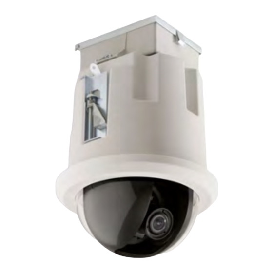
- Page 1 AutoDome 700 Series IP PTZ Camera AutoDome 700 Series Installation Manual...
-
Page 3: Table Of Contents
AutoDome 700 Series IP PTZ Camera Table of Contents | en Table of Contents Safety Important Safety Instructions Safety Precautions Important Notices Customer Support and Service Installing the Pendant Arm Wall, Corner, and Mast (Pole) Mounts Unpacking 2.1.1 Parts List 2.1.2... - Page 4 | Table of Contents AutoDome 700 Series IP PTZ Camera Installing the In-Ceiling Mount Unpacking 4.1.1 Parts List 4.1.2 Description 4.1.3 Tools Required Pre-installation Check List Dimensions Prepare Drywall Ceiling for Installation Prepare Suspension Ceiling for Installation Wire the Interface Box 4.6.1...
-
Page 5: Safety
AutoDome 700 Series IP PTZ Camera Safety | en Safety Important Safety Instructions Read, follow, and retain for future reference all of the following safety instructions. Heed all warnings on the unit and in the operating instructions before operating the unit. - Page 6 17. Attachments, changes or modifications - Only use attachments/accessories specified by the manufacturer. Any change or modification of the equipment, not expressly approved by Bosch, could void the warranty or, in the case of an authorization agreement, authority to operate the equipment.
-
Page 7: Safety Precautions
AutoDome 700 Series IP PTZ Camera Safety | en Safety Precautions DANGER! This symbol indicates an imminently hazardous situation such as “Dangerous Voltage” inside the product. If not avoided, this will result in an electrical shock, serious bodily injury, or death. - Page 8 Please dispose of these units at an environmentally compatible recycling facility, per European Directive 2002/96/EC. Environmental statement - Bosch has a strong commitment towards the environment. This unit has been designed to respect the environment as much as possible.
- Page 9 Because the ISDN circuits are treated like telephone-network voltage, avoid connecting the SELV circuit to the Telephone Network Voltage (TNV) circuits. Video loss - Video loss is inherent to digital video recording; therefore, Bosch Security Systems cannot be held liable for any damage that results from missing video information. To minimize the risk of lost digital information, Bosch Security Systems recommends multiple, redundant recording systems, and a procedure to back up all analog and digital information.
- Page 10 UL MAKES NO REPRESENTATIONS, WARRANTIES, OR CERTIFICATIONS WHATSOEVER REGARDING THE PERFORMANCE OR RELIABILITY OF ANY SECURITY OR SIGNALING- RELATED FUNCTIONS OF THIS PRODUCT. Copyright This user guide is the intellectual property of Bosch Security Systems, Inc. and is protected by copyright. All rights reserved. Trademarks All hardware and software product names used in this document are likely to be registered trademarks and must be treated accordingly.
-
Page 11: Customer Support And Service
AutoDome 700 Series IP PTZ Camera Safety | en Customer Support and Service If this unit needs service, contact the nearest Bosch Security Systems Service Center for authorization to return and shipping instructions. Service Centers Telephone: 800-366-2283 or 585-340-4162 Fax: 800-366-1329 Email: cctv.repair@us.bosch.com... -
Page 12: Installing The Pendant Arm Wall, Corner, And Mast (Pole) Mounts
Verify that all the parts listed in the Parts List below are included. If any items are missing, notify your Bosch Security Systems Sales or Customer Service Representative. Refer to Section 1.4 Customer Support and Service, page 11, for contact information. -
Page 13: Description
No. 2 Phillips screwdriver – Socket wrench and 9/16-in. socket – Banding tool (Bosch P/N TC9311PM3T) - if installing a mast (pole) mount – 3/4 in. (20-mm) NPS right angle conduit connector - if installing a mast (pole) mount with a VG4-ARMPLATE... -
Page 14: Mount Power Supply Box
Mast Plate to the pole. Contact your Bosch Sales Representative to order Banding Tool P/N TC9311PM3T. Secure the Power Supply Box to the Corner Plate or Mast Plate using the four (4) 3/8 x 1-3/4-inch bolts and split lock washers (supplied). -
Page 15: Route Wires And Attach Connectors
AutoDome 700 Series IP PTZ Camera Installing the Pendant Arm Wall, Corner, and Mast (Pole) Mounts | en Route Wires and Attach Connectors Power wires must be routed to the left (front) side of the Power Supply Box through a separate conduit. - Page 16 | Installing the Pendant Arm Wall, Corner, and Mast (Pole) Mounts AutoDome 700 Series IP PTZ Camera Attach the supplied 6-pin Control Data I/O Plug to the incoming control wires. Refer to connector P106 in Table 2.1, Page 18, for wire connections. This step is not required with Fiber Optic models, since control passes through the fiber optic cable.
-
Page 17: Power Supply Box Connections
AutoDome 700 Series IP PTZ Camera Installing the Pendant Arm Wall, Corner, and Mast (Pole) Mounts | en 2.4.2 Power Supply Box Connections The following figure is a detailed illustration of the Pendant Arm Power Supply Box, which includes the fuse specifications. -
Page 18: Route Power Through Intermediate Power Supply Box
| Installing the Pendant Arm Wall, Corner, and Mast (Pole) Mounts AutoDome 700 Series IP PTZ Camera The following table lists the Power Supply Box connectors: Connector Pin 1 Pin 2 Pin 3 Pin 4 Pin 5 Pin 6... - Page 19 AutoDome 700 Series IP PTZ Camera Installing the Pendant Arm Wall, Corner, and Mast (Pole) Mounts | en 120/230 VAC Power In Transformer Ground Wire In/Out Conduit (1/2 in. [15 mm] NPS Fitting P101 Connector 24 VAC Power Out to VG4-PA0...
- Page 20 | Installing the Pendant Arm Wall, Corner, and Mast (Pole) Mounts AutoDome 700 Series IP PTZ Camera WARNING! Ensure that you connect the outgoing power supply wires to the P107 heater connectors (HN and HL). The heater power (XF103) fuse can handle a higher amperage (3.15 A) than the camera power (XF102) fuse (2.0 A).
-
Page 21: Attach Pendant Arm To Power Supply Box
AutoDome 700 Series IP PTZ Camera Installing the Pendant Arm Wall, Corner, and Mast (Pole) Mounts | en Attach Pendant Arm to Power Supply Box The bottom hinge pin of the Pendant Arm is provided with a Hinge Pin Stop to hold the hinge open while attaching the arm to the Power Supply Box. -
Page 22: Make Connections In Power Supply Box
| Installing the Pendant Arm Wall, Corner, and Mast (Pole) Mounts AutoDome 700 Series IP PTZ Camera Make Connections in Power Supply Box Refer to Table 2.2, Page 19 to locate the various connectors in the power supply box and make the following connections detailed below. -
Page 23: Installing The Vg4-A-Armplate
Follow the instructions provided with the banding tool to securely mount the Mast Plate to the pole. Contact your Bosch Sales Representative to order Banding Tool P/N TC9311PM3T. -
Page 24: Attach The Pendant Arm To The Mounting Plate
| Installing the Pendant Arm Wall, Corner, and Mast (Pole) Mounts AutoDome 700 Series IP PTZ Camera Once the Mounting Plate (item 1, below) is attached to the Mast Plate (item 2), connect the right angle conduit (item 3) to the Mounting Plate through the empty conduit hole as shown below: Ensure that the mounting plate is secure. -
Page 25: Route And Connect Wires To A Power Supply Box
AutoDome 700 Series IP PTZ Camera Installing the Pendant Arm Wall, Corner, and Mast (Pole) Mounts | en Open the top hinge by pushing its pin lever up and holding it. Note: Both Hinge Pins must be fully compressed to open (unlock) the hinges of the Pendant Arm and before proceeding to the next step. - Page 26 | Installing the Pendant Arm Wall, Corner, and Mast (Pole) Mounts AutoDome 700 Series IP PTZ Camera Route all incoming wires through one of the conduits at the bottom of the Mounting Plate. For a mast mount, route all wires through the right-angle conduit.
- Page 27 AutoDome 700 Series IP PTZ Camera Installing the Pendant Arm Wall, Corner, and Mast (Pole) Mounts | en Connect the incoming RJ45 video connector, installed previously, to the UTP Video/ Ethernet cable (cable 5). Refer to Section 5 Cable and Wire Standards, page 57, for detailed wire and connection information.
-
Page 28: Attach Pendant To Arm And Tighten
| Installing the Pendant Arm Wall, Corner, and Mast (Pole) Mounts AutoDome 700 Series IP PTZ Camera Attach Pendant to Arm and Tighten NOTICE! Before attaching the AutoDome Pendant, visually inspect the dome and arm connectors for any blocked pin holes or bent pins. - Page 29 AutoDome 700 Series IP PTZ Camera Installing the Pendant Arm Wall, Corner, and Mast (Pole) Mounts | en Rotate the dome housing down to a vertical position and gently push upward to engage the connector on top of the dome housing.
-
Page 30: Installing The Roof Parapet And Pipe Mounts
The VG4-A-9230 Series are stationary mounts intended for rooftop parapet vertical walls. They are made of light weight aluminum with a corrosion-resistant finish and are used for all Bosch AutoDome Cameras up to a rated load of 29 kg (64 lb). These mounts can be fitted to the inside or outside of parapet walls and can swivel for ease of positioning and for servicing the AutoDome. -
Page 31: Pre-Installation Check List
AutoDome 700 Series IP PTZ Camera Installing the Roof Parapet and Pipe Mounts | en Pre-installation Check List Determine the location and distance for the power supply box based on its voltage and current consumption. Refer to Section 5 Cable and Wire Standards, page 57 for wiring information and distances. -
Page 32: Mount Power Supply Box
| Installing the Roof Parapet and Pipe Mounts AutoDome 700 Series IP PTZ Camera Mount Power Supply Box Before mounting the Power Supply Box decide if you will be wiring the box through the holes in the bottom or back of the box. If wiring the box through the back, move the two (2) seal plugs to the bottom holes before mounting. -
Page 33: Attach Cover Door
AutoDome 700 Series IP PTZ Camera Installing the Roof Parapet and Pipe Mounts | en 3.3.1 Attach Cover Door Compress the bottom hinge pin by pushing the pin lever down and then rotate it behind the Hinge Pin Stop. The power box Cover Door provides a Hinge Pin Stop to hold the bottom hinge open while attaching the door. -
Page 34: Route Wires And Attach Connectors
| Installing the Roof Parapet and Pipe Mounts AutoDome 700 Series IP PTZ Camera Route Wires and Attach Connectors Power wires must be routed to the left (front) side of the Power Supply Box through a separate conduit. All video, control, and alarm wires must be routed through a second conduit to the right side of the box. - Page 35 AutoDome 700 Series IP PTZ Camera Installing the Roof Parapet and Pipe Mounts | en – The second method is to bypass the Power Supply Box and route the video, control, and alarm wires directly to the Interface Board. You connect only the power wires inside the Power Supply Box.
-
Page 36: Wiring The Power Supply Box
| Installing the Roof Parapet and Pipe Mounts AutoDome 700 Series IP PTZ Camera 3.4.2 Wiring the Power Supply Box Route the high voltage 115/230 VAC lines through the conduit fitting on the left side of the box. NOTICE! The Power Supply Box with transformer comes with a barrier that separates the high voltage side on the left from the low voltage 24 VAC side on the right. -
Page 37: Power Supply Box Connections
AutoDome 700 Series IP PTZ Camera Installing the Roof Parapet and Pipe Mounts | en 3.4.3 Power Supply Box Connections The following figure is a detailed illustration of the Roof or Pipe Mount Power Supply Box, which includes the fuse specifications. -
Page 38: Installing The Vg4-A-9230 Roof Parapet Mount
| Installing the Roof Parapet and Pipe Mounts AutoDome 700 Series IP PTZ Camera The following table lists the Power Supply Box connectors: Connector Pin 1 Pin 2 Pin 3 Pin 4 Pin 5 Pin 6 Ground Grounding Screw... - Page 39 AutoDome 700 Series IP PTZ Camera Installing the Roof Parapet and Pipe Mounts | en Prepare the mounting surface for the type of fastener by drilling holes for the mounting anchors as required. Figure 3.6 Parapet Wall Mount Bracket and Roof Mount Plate...
- Page 40 | Installing the Roof Parapet and Pipe Mounts AutoDome 700 Series IP PTZ Camera Remove the End Cap from the front of the arm and feed the video, control, and power wires up through the bottom of the pipe arm and out the front end.
-
Page 41: Installing The Vg4-A-9543 Pipe Mount
AutoDome 700 Series IP PTZ Camera Installing the Roof Parapet and Pipe Mounts | en 11. Run a bead of RTV Silicon sealant around the down pipe/Dome Cap interface to seal any gaps between the down pipe and the Dome Cap. -
Page 42: Wire The Pipe Interface Board
| Installing the Roof Parapet and Pipe Mounts AutoDome 700 Series IP PTZ Camera Apply the supplied thread sealant to the threads on the Pipe. – Make sure all surfaces are clean and dry. – Apply a bead of sealant completely around the leading threads of the male fitting. -
Page 43: Connecting Wires To The Pipe Interface Board
AutoDome 700 Series IP PTZ Camera Installing the Roof Parapet and Pipe Mounts | en Ref. Description Connector Wire Gauge Description Pipe Interface Module Video Coax In J102 6-pin Connector Alarms In (3-7) P103 4-pin Connector Alarms Out (1-3) P102 100 Ω... - Page 44 | Installing the Roof Parapet and Pipe Mounts AutoDome 700 Series IP PTZ Camera To connect alarm inputs and outputs, attach the supplied 6-pin Alarms In and the 4-pin Alarms Out connector plugs with flying leads to the appropriate alarm wires. Then connect the plugs to their mating connectors P103 and P102 on the Pipe Interface Board.
- Page 45 AutoDome 700 Series IP PTZ Camera Installing the Roof Parapet and Pipe Mounts | en Insert the Pipe Interface Board into the down pipe and fasten the three (3) retaining screws to secure the board to the Dome Cap. CAUTION! Be careful not to strip the threads when tightening the Pipe Interface Board retaining screws.
-
Page 46: Attach Pendant To Pipe And Tighten
| Installing the Roof Parapet and Pipe Mounts AutoDome 700 Series IP PTZ Camera Attach Pendant to Pipe and Tighten Before attaching the Pendant, visually inspect the Pendant dome and the Interface Board connectors for any blocked pin holes and bent pins. -
Page 47: Make Connections In The Power Supply Box
AutoDome 700 Series IP PTZ Camera Installing the Roof Parapet and Pipe Mounts | en Drop the Pendant down slightly to engage the dome hook and hinge pin of the Dome Cap, allowing the dome to rotate around the hinge pin. -
Page 48: Installing The In-Ceiling Mount
Verify that all the parts listed in the product's Parts List below are included. If any items are missing, notify your Bosch Security Systems Sales or Customer Service Representative. Refer to Section 1.4 Customer Support and Service, page 11, for contact information. -
Page 49: Dimensions
AutoDome 700 Series IP PTZ Camera Installing the In-Ceiling Mount | en Dimensions ø197.17 7.762 191.03 7.521 21.29 0.838 96.35 3.793 R 77.00 ø225.69 3.032 8.885 inches Figure 4.1 In-ceiling Dimensional Outline Prepare Drywall Ceiling for Installation Choose the desired location to mount the dome. - Page 50 | Installing the In-Ceiling Mount AutoDome 700 Series IP PTZ Camera Place the Bracket Assembly over the ceiling tile, which is used to mount the In-Ceiling AutoDome. Then snap the Bar Clips of the bracket to the ceiling rails.
-
Page 51: Wire The Interface Box
AutoDome 700 Series IP PTZ Camera Installing the In-Ceiling Mount | en Tighten the four (4) securing screws to the Bracket Assembly. Figure 4.4 Tighten Bracket Securing Screw Secure the Bracket Assembly to an overhead securing point with a safety wire. - Page 52 | Installing the In-Ceiling Mount AutoDome 700 Series IP PTZ Camera Connect the 24 VAC power wires to the P101 connector in the Interface Box. To connect alarm inputs and outputs, attach the supplied 6-pin Alarms In and the 4-pin Alarms Out connector plugs with flying leads to the appropriate alarm wires.
-
Page 53: Interface Box Connections
AutoDome 700 Series IP PTZ Camera Installing the In-Ceiling Mount | en 4.6.2 Interface Box Connections The following figure is a detailed illustration of the In-ceiling Interface box. Figure 4.7 In-ceiling Interface Box Fiber Optics Coax Video UTP/Ethernet Video Alarm In... -
Page 54: Attach Housing To The Interface Box
| Installing the In-Ceiling Mount AutoDome 700 Series IP PTZ Camera The following table summarizes the pin connectors and their function: Connector Pin 1 Pin 2 Pin 3 Pin 4 Pin 5 Pin 6 Pin 7 P103 Alarms In... - Page 55 AutoDome 700 Series IP PTZ Camera Installing the In-Ceiling Mount | en Tighten the two (2) Thumbscrews to secure the Interface Box to the housing. Figure 4.9 In-Ceiling Housing and Interface Box Interface Box Thumb Screw Ball Stud Tether Point...
-
Page 56: Secure Housing To Ceiling
| Installing the In-Ceiling Mount AutoDome 700 Series IP PTZ Camera Secure Housing to Ceiling The In-ceiling Housing is secured to the ceiling by two (2) screw clamps. Insert the In-ceiling Mount Assembly through the hole in the ceiling. -
Page 57: Cable And Wire Standards
AutoDome 700 Series IP PTZ Camera Cable and Wire Standards | en Cable and Wire Standards CAUTION! Installation should only be performed by qualified service personnel in accordance with the National Electrical Code or applicable local codes. CAUTION! All wires for installation applications must be routed through a grounded conduit. -
Page 58: Using A Fiber Optic Ethernet Media Converter To Transmit Video And Control
Using a Fiber Optic Ethernet Media Converter to Transmit Video and Control The fiber optic media converter kit, available for AutoDome 700 Series cameras, is designed to transmit 10/100 Mbps Ethernet signals over fiber optic cable using 10/100 Mbps Small Form-factor Pluggable (SFP) modules. - Page 59 AutoDome 700 Series IP PTZ Camera Cable and Wire Standards | en Audio Connections Remove the 100 Ω termination resistor from the Biphase terminals. Connect the audio line level source to the Biphase C+ input terminal. Connect the audio signal ground to the Biphase C- input terminal.
-
Page 60: Alarms And Relay Connections
| Alarms and Relay Connections AutoDome 700 Series IP PTZ Camera Alarms and Relay Connections Alarm Inputs The AutoDome provides two alarm inputs. Each input can be activated by dry contact devices such as pressure pads, passive infrared detectors, door contacts, and similar devices. The table below summarizes the size and distance wires. -
Page 61: Connecting A Normally Closed Alarm
AutoDome 700 Series IP PTZ Camera Alarms and Relay Connections | en 6.2.2 Connecting a Normally Closed Alarm Connect the alarm to the appropriate input (1 or 2) and ground at the AutoDome. Figure 6.2 N.C. Normally Closed Non-supervised Connections... -
Page 62: Bubble Handling And Cleaning
| Bubble Handling and Cleaning AutoDome 700 Series IP PTZ Camera Bubble Handling and Cleaning The bubble is made of Acrylic or Polycarbonate, depending on the application. Polycarbonate bubbles provide high impact resistance, and it’s optical clarity is comparable to glass or acrylic, although it’s surface is much softer. -
Page 63: Cleaning The Bubble Exterior
AutoDome 700 Series IP PTZ Camera Bubble Handling and Cleaning | en To remove the bubble from an in-ceiling housing Loosen the lockscrew (item 1 in the illustration below) in the trim ring using a P1 or smaller Phillips screwdriver until the bubble can rotate freely. -
Page 64: Index
AutoDome 700 Series IP PTZ Camera Index | en Index alarm connectors 16 IEE 802.3af 57 alarm inputs 60 in-ceiling mount 48 non-supervised 60 attaching housing 54 normally closed non-supervised 61 interface box connections 53 normally open non-supervised 60 parts 48... - Page 65 | Index AutoDome 700 Series IP PTZ Camera power supply box 34 attaching to pendant arm 21 connections for pendant arm 18 connections for roof parapet or pipe mount 12 installing with in-ceiling mount 48 installing with pendant arm, corner or mast mount...
- Page 68 Bosch Security Systems, Inc. 850 Greenfield Road Lancaster, PA 17601 U.S.A. www.boschsecurity.com © Bosch Security Systems, Inc., 2011...