Table of Contents
Advertisement
Quick Links
Advertisement
Table of Contents

Related Manuals for Bosch PXI-CORE Edge controller


Summary of Contents for Bosch PXI-CORE Edge controller
- Page 1 PXI‑CORE Edge controller User manual...
-
Page 3: Table Of Contents
PXI-CORE Edge controller Table of contents | en Table of contents Important product information Disposal instructions FCC Statement - Wired Class A digital device (unintentional radiator) CE Class A Statement FCC suppliers declaration of conformity KCC Statement About this manual... - Page 4 | Table of contents PXI-CORE Edge controller Battery change Technical data 2023-03 | V01 | F01U395004 Bosch Security Systems B.V. User manual...
-
Page 5: Important Product Information
PXI-CORE Edge controller Important product information | en Important product information Warning! Operation of this equipment in a residential environment could cause radio interference. Disposal instructions Old electrical and electronic appliances. Electrical or electronic devices that are no longer serviceable must be collected separately and sent for environmentally compatible recycling (in accordance with the European Waste Electrical and Electronic Equipment Directive). -
Page 6: Kcc Statement
Responsible party Bosch Security Systems LLC 130 Perinton Parkway 14450 Fairport, NY, USA www.boschsecurity.us KCC Statement 기자재명 : PXI-CORE Edge controller 모델명 : PXI-CORE 수입업체(상호)명 : 로버트보쉬코리아유한회사 제조국 : 독일 (Germany) 제조일자 : 별도표기 R-R-RB9-PXICORE 제조자 : Bosch Security Systems B.V. -
Page 7: About This Manual
Notice of liability While every effort has been taken to ensure the accuracy of this document, neither Bosch Security Systems nor any of its official representatives shall have any liability to any person or entity with respect to any liability, loss or damage caused or alleged to be caused directly or indirectly by the information contained in this document. -
Page 8: About The Pxi-Core
About the PXI-CORE Introduction The PXI-CORE Edge controller is the HW base unit for smart integration. It consists of a compact DIN-rail mountable hardware unit, Linux operating system and firmware. Smart integration stands for integration between Bosch Building Technology systems and devices. - Page 9 – 1) Go to and click Settings > Apps. – 2) Set the PXI-CORE edge controller in Service Mode by clicking the blue Operation mode/Service mode button. – 3) When the LED (H) color changes from green to blinking blue, click the Install from file button.
-
Page 10: Detailed Installation Procedures And Instructions
| Detailed installation procedures and instructions PXI-CORE Edge controller Detailed installation procedures and instructions This section provides mounting instructions and installation instructions. It provides installation methods commonly encountered in commercial applications and all applicable codes. Follow the mechanical installation and electrical installation steps in the order they are set up in the next chapters. - Page 11 PXI-CORE Edge controller Detailed installation procedures and instructions | en – IMPORTANT: Connect the voltage only after the device is mechanically and electrically mounted correctly. Mount the device on a 35 mm standard mounting rail. The preferred overall height of the mounting rail is 7.5 mm (corresponds to TH 35‑7.5 acc.
- Page 12 | Detailed installation procedures and instructions PXI-CORE Edge controller Disengage the device pulling down the lower disengaging mechanism with the suitable tool (A). – The base latches are locked in the open position. Remove the device vertically from the mounting rail (B).
-
Page 13: Electrical Installation
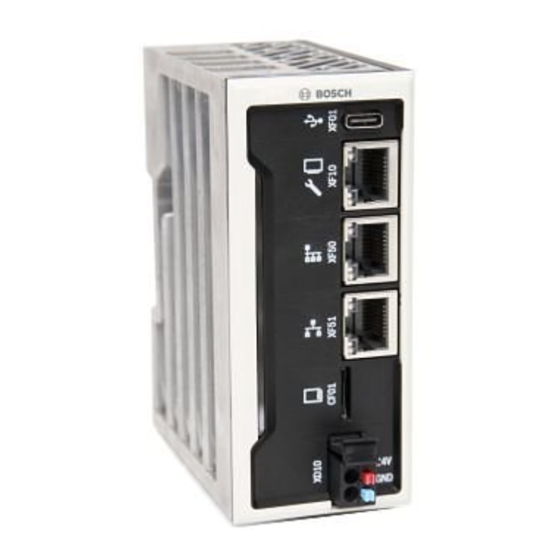
PXI-CORE Edge controller Detailed installation procedures and instructions | en Electrical installation The PXI‑CORE edge controller communicates with your configuration device via Ethernet port XF51 connected to an Ethernet network, and is DC‑powered from an external 24 VDC power supply. If required, the XF10 Ethernet port can be used for connection to your computer (PC). -
Page 14: Ethernet Ports
| Detailed installation procedures and instructions PXI-CORE Edge controller 4.2.1 Ethernet ports The PXI-CORE edge controller has two functional Ethernet connectors: XF51 and XF10. – XF51 is the main Ethernet port, and is the connection to an Ethernet network. –... - Page 15 Connect the +24 V to the red connection point (1). When reinstalling the press fit plug to the device, align the bottom fit of the plug with the bottom horizontal pins in the PXI-CORE edge controller. Align the connector obliquely. Bosch Security Systems B.V.
-
Page 16: Sd Card Slot Cf01
| Detailed installation procedures and instructions PXI-CORE Edge controller When the bottom fit of the plug lands on the horizontal pins of the device, engage the plug upwards and towards the connector holder on the device. You hear a click noise when the connector is locked in the final position. -
Page 17: Battery Case Gb01
PXI-CORE Edge controller Web-based graphical user interface | en 4.2.4 Battery case GB01 An internal battery is included and working in the device upon delivery. The battery is used to extend the buffer time of the real‑time internal clock. A circuit monitors the battery state. A discharged battery causes an incorrect system time. -
Page 18: Date & Time
5.2.6 Proxy This function is used in cases where the internet connectivity requires a proxy server. This might be needed if you want to connect the PXI-CORE edge controller to the remote portal. 5.2.7 Shutdown The PXI‑CORE can be shutdown or restarted. -
Page 19: Diagnostics
Data Layer is not used! Do not to use the Data Layer setting or its settings on the PXI-CORE edge controller. Using the Data Layer results in malfunctioning of the PXI-CORE edge controller and its installed applications and configurations. –... - Page 20 | Web-based graphical user interface PXI-CORE Edge controller – Configurations Notice! The Configurations menu has no specific use for the BT user. 2023-03 | V01 | F01U395004 Bosch Security Systems B.V. User manual...
-
Page 21: Troubleshooting
If you are not successful in connecting to the PXI-CORE graphical user interface via the IPv6 address, fall back to the static IPv4 address of the PXI-CORE edge controller. To connect the PXI-CORE graphical user interface via the static IPv4 address: Connect the PXI‑CORE port XF51 to your main network. -
Page 22: App Installation Problems
If the upload of an app is successful but the app is not installed: – Make sure you only use official Bosch-signed apps provided. By default, apps from unknown sources are not accepted for security reasons. 2023-03 | V01 | F01U395004 Bosch Security Systems B.V. -
Page 23: Maintenance
Operate the device within specifications When designing the device, Bosch largely avoided using wear parts. The parts subject to wear and tear are dimensioned to last longer than the lifetime of the products when they are operated normally. - Page 24 | Maintenance PXI-CORE Edge controller – Test of the associated functions. Battery change Exchange the battery of the device every three years, if NOT operational 24/7. Under normal use the battery lasts longer than three years. If replacement is necessary, replace it with a CR1025 type battery.
- Page 25 PXI-CORE Edge controller Technical data | en Technical data Electrical Nominal voltage 24 VDC SELV/PELV Maximum voltage range of the supply voltage allowed 18 VDC to 31.2 VDC (incl. all tolerances and ripple) Max. current consumption at a nominal voltage of 24 V 320 mA...
- Page 26 | Technical data PXI-CORE Edge controller 2023-03 | V01 | F01U395004 Bosch Security Systems B.V. User manual...
- Page 28 Bosch Security Systems B.V. Torenallee 49 5617 BA Eindhoven Netherlands www.boschsecurity.com © Bosch Security Systems B.V., 2023 Building solutions for a better life. 202303271615...