Siemens SIMATIC ET 200AL Manual
10-link digital output module dq 8x24vdc/2a 8xm12
Hide thumbs
Also See for SIMATIC ET 200AL:
- System manual (2255 pages) ,
- Manual (86 pages) ,
- Equipment manual (46 pages)
Table of Contents
Advertisement
Quick Links
Advertisement
Table of Contents

Related Manuals for Siemens SIMATIC ET 200AL


Summary of Contents for Siemens SIMATIC ET 200AL
- Page 2 IO-Link digital output module DQ 8x24VDC/2A 8xM12 (6ES7142-5AF00-0BL0) Preface ET 200AL IO-Link I/O modules Documentation Guide SIMATIC Product overview ET 200AL Wiring IO-Link digital output module DQ 8x24VDC/2A 8xM12 Parameters/address space (6ES7142-5AF00-0BL0) Interrupts/diagnostic Equipment Manual alarms Technical specifications Dimension drawing 08/2021 A5E47926730-AB...
- Page 3 Note the following: WARNING Siemens products may only be used for the applications described in the catalog and in the relevant technical documentation. If products and components from other manufacturers are used, these must be recommended or approved by Siemens. Proper transport, storage, installation, assembly, commissioning, operation and maintenance are required to ensure that the products operate safely and without any problems.
-
Page 4: Preface
Purpose of the documentation This manual supplements the system manual ET 200AL IO-Link (https://support.automation.siemens.com/WW/view/en/109773203). Functions that generally relate to the distributed I/O system ET 200AL IO-Link I/O modules are described there. The information provided in this manual and in the system manual and function manuals supports you in commissioning the ET 200AL IO-Link I/O modules. - Page 5 Siemens' products and solutions undergo continuous development to make them more secure. Siemens strongly recommends that product updates are applied as soon as they are available and that the latest product versions are used. Use of product versions that are no longer supported, and failure to apply the latest updates may increase customers' exposure to cyber threats.
-
Page 6: Table Of Contents
Table of contents Preface ..............................3 ET 200AL IO-Link I/O modules Documentation Guide ................6 Product overview ........................... 9 Properties ..........................9 Operator controls and display elements................11 Wiring ..............................12 Terminal and block diagram ....................12 Pin assignment ........................13 Parameters/address space ........................ -
Page 7: 200Al Io-Link I/O Modules Documentation Guide
ET 200AL IO-Link I/O modules Documentation Guide The documentation for the SIMATIC ET 200AL IO-Link I/O modules is arranged into three areas. This arrangement enables you to access the specific content you require. Basic information The system manual describes in detail the configuration, installation, wiring and commissioning of the distributed I/O system SIMATIC ET 200AL IO-Link I/O modules. - Page 8 You must register once to use the full functionality of "mySupport". You can find "mySupport" on the Internet (https://support.industry.siemens.com/My/ww/en). "mySupport" - Documentation With "mySupport", your personal workspace, you make the best out of your Industry Online Support.
- Page 9 You can find the TIA Selection Tool on the Internet (https://support.industry.siemens.com/cs/ww/en/view/109767888). PRONETA SIEMENS PRONETA (PROFINET network analysis) allows you to analyze the plant network during commissioning. PRONETA has two core functions: • The topology overview automatically scans the PROFINET and all connected components.
-
Page 10: Product Overview
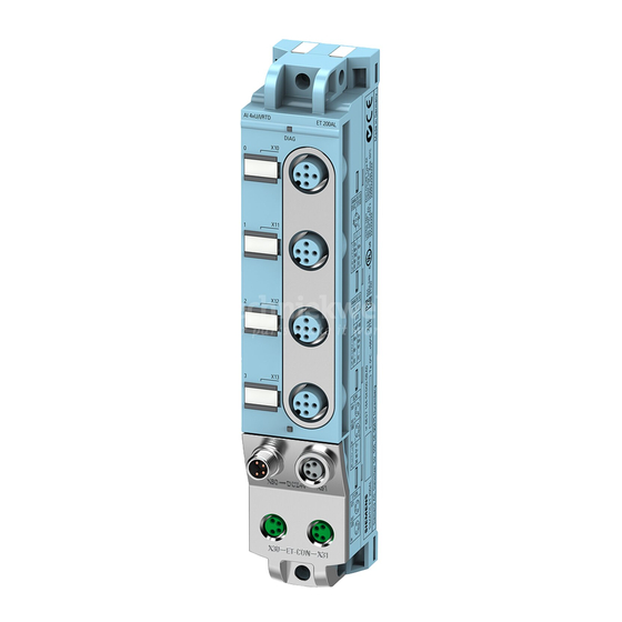
Product overview Properties Article number 6ES7142-5AF00-0BL0 View of the module Figure 2-1 View of the DQ 8x24VDC/2A 8xM12 IO-Link digital output module IO-Link digital output module DQ 8x24VDC/2A 8xM12 (6ES7142-5AF00-0BL0) Equipment Manual, 08/2021, A5E47926730-AB... - Page 11 • M12 sealing cap See also You can find more information on accessories in the Accessories/spare parts section of the ET 200AL distributed I/O system (https://support.automation.siemens.com/WW/view/en/109773203) IO-Link I/O modules system manual. IO-Link digital output module DQ 8x24VDC/2A 8xM12 (6ES7142-5AF00-0BL0) Equipment Manual, 08/2021, A5E47926730-AB...
-
Page 12: Operator Controls And Display Elements
Product overview 2.2 Operator controls and display elements Operator controls and display elements The figure below shows the operator controls and display elements of the IO-Link DQ 8x24VDC/2A 8xM12 digital output module. ① DIAG: LED display for the diagnostic status ②... -
Page 13: Wiring
Wiring Terminal and block diagram The example in the figure below shows the pin assignment of signal outputs. ① Output to 2L+ Supply voltage 1L+ (non-switched) ② DQ circuit Ground 1M (non-switched) ③ Microcontroller Load voltage 2L+ (switched) ④ Monitoring Ground 2M (switched) ⑤... -
Page 14: Pin Assignment
Wiring 3.2 Pin assignment Pin assignment Pin assignment of the sockets for digital outputs The table below shows the pin assignment of the 8 sockets for the connection of the digital outputs. Table 3- 1 Pin assignment for digital outputs Assignment Front view of the sockets X10 to X17 sockets for digital outputs... - Page 15 Wiring 3.2 Pin assignment Pin assignment of the connector for IO-Link The following table shows the pin assignment of the connector for IO-Link. The IO-Link interface corresponds to the specification according to port Class A. Table 3- 3 Pin assignment of the IO-Link interface Assignment Front view of the connector (Port Class Unassigned...
-
Page 16: Parameters/Address Space
Parameters/address space Parameters The following table shows the parameters for the DQ 8x24VDC/2A 8xM12 IO-Link digital output module. Table 4- 1 Parameters Parameters Value range Default Scope ISDU ISDU index subindex Value (decimal) (decimal) Diagnostics: Missing load volt- Disable Disable Module age 2L+ Enable... -
Page 17: Address Space
The structure of the IODD is identical for all devices from all manufacturers. The structure of the IODD is always represented in the same manner by the IO-Link Configuration Tool of the master manufacturer (for Siemens, S7-PCT). This ensures that the handling is the same for all IO-Link devices regardless of the manufacturer. -
Page 18: Interrupts/Diagnostic Alarms
Interrupts/diagnostic alarms Status and error displays LED displays The figure below shows the LED displays (status and error displays) of the DQ 8x24VDC/2A 8xM12 IO-Link digital output module. ① Diagnostic status (DIAG) (red/green) ② Channel status (0 to 7) (green) ③... - Page 19 Interrupts/diagnostic alarms 5.1 Status and error displays Meaning of the LEDs The following tables set out the meaning of the status and error displays. Remedial measures for diagnostic alarms can be found in the section Diagnostics alarms (Page 19). DIAG LED Table 5- 1 Error display of the DIAG LED DIAG LED...
-
Page 20: Interrupts
Interrupts/diagnostic alarms 5.2 Interrupts Interrupts The DQ 8x24VDC/2A 8xM12 IO-Link digital output module supports diagnostic interrupts. Diagnostic interrupt The digital output module generates a diagnostic interrupt at the following events: • Short-circuit of outputs to ground • Load voltage 2L+ missing or too low Diagnostics alarms For each diagnostic event, a diagnostics alarm is issued and the LED DIAG flashes red on the digital output module. -
Page 21: Technical Specifications
Technical specifications of the DQ 8x24VDC/2A 8xM12 IO-Link digital output module The following table shows the technical specifications as of the issue date. You can find a data sheet including daily updated technical specifications on the Internet (https://support.industry.siemens.com/cs/de/en/pv/6ES7142-5AF00-0BL0/td?dl=en). Article number 6ES7142-5AF00-0BL0... - Page 22 Technical specifications Article number 6ES7142-5AF00-0BL0 Load resistance range 12 Ω • lower limit 4 kΩ • upper limit Output voltage L+ (-0.8 V) • for signal "1", min. Output current 2 A (45 °C); 1 A (55 °C) • for signal "1" rated value 2 A;...
- Page 23 Technical specifications Article number 6ES7142-5AF00-0BL0 Potential separation between the load voltages Potential separation channels • between the channels • between the channels and the power supply of the electronics Isolation Isolation tested with 707 V DC (type test) Standards, approvals, certificates Suitable for safety-related tripping of standard Yes;...
- Page 24 Technical specifications Derating curve The following figure show the load current derating with mounting clearance observed, depending on the ambient temperature. Figure 6-1 Derating curve IO-Link digital output module DQ 8x24VDC/2A 8xM12 IO-Link digital output module DQ 8x24VDC/2A 8xM12 (6ES7142-5AF00-0BL0) Equipment Manual, 08/2021, A5E47926730-AB...
-
Page 25: Dimension Drawing
Dimension drawing The figure below shows the dimension drawing of the DQ 8x24VDC/2A 8xM12 IO-Link digital output module in front and side views. Figure A-1 Dimension drawing IO-Link digital output module DQ 8x24VDC/2A 8xM12 (6ES7142-5AF00-0BL0) Equipment Manual, 08/2021, A5E47926730-AB...