
Related Manuals for Bosch rexroth Sytronix SvP 7030 IMC


Summary of Contents for Bosch rexroth Sytronix SvP 7030 IMC
- Page 1 Operating Manual Sytronix SvP 7030 IMC Variable-speed pump drive RE 62312-B, 03.2022...
- Page 2 Schutzvermerk © Bosch Rexroth AG ©2022 Alle Rechte vorbehalten, auch bezüglich jeder Verfügung, Verwertung, Reproduktion, Bearbeitung, Weitergabe sowie für den Fall von Schutzrechtsanmeldungen. Verbindlichkeit Die angegebenen Daten dienen allein der Produktbeschreibung und sind nicht als zugesicherte Eigenschaften im Rechtssinne zu verstehen. Änderungen im Inhalt der Dokumentation und Liefermöglichkeiten der Produkte sind vorbehalten.
-
Page 3: Table Of Contents
Unpacking........... . . RE 62312-B, 03.2022 Bosch Rexroth AG... - Page 4 On-board connection points....... . 116 7.5.24 Connection points of the components......119 Bosch Rexroth AG RE 62312-B, 03.2022...
- Page 5 14.4 Fault table........... . . 173 15 Service and support 16 Index RE 62312-B, 03.2022 Bosch Rexroth AG...
- Page 6 Sytronix SvP 7030 IMC 6 / 186 Bosch Rexroth AG RE 62312-B, 03.2022...
-
Page 7: About This Documentation
Operating instructions Axial piston units for variable-speed drives A10FZO, RE 91485 Data sheet A10VZO, A10FZG and A10VZG Axial piston units for variable-speed drives A10FZO, RE 91485-01-B Operating A10VZO, A10FZG and A10VZG series 10 instructions RE 62312-B, 03.2022 Bosch Rexroth AG... -
Page 8: Representation Of Information
If this information is disregarded, the product cannot be used or operated in an optimum manner. ● Individual, independent action Numbered instruction: The numbers indicate that the actions must be carried out one after the other. Bosch Rexroth AG RE 62312-B, 03.2022... -
Page 9: Designations
Firmware for drive controllers A10FZO Axial piston pump, fixed displacement HM20 Pressure transducer IndraWorks Ds Bosch Rexroth software tool for drive commissioning MPA02 Motor-pump unit consisting of internal gear pump and MS2N motor MS2N Servo motor PGH/PGM... - Page 10 Sytronix SvP 7030 IMC 10 / 186 Representation of information Bosch Rexroth AG RE 62312-B, 03.2022...
-
Page 11: Safety Instructions
For example, in explo- sion-protection areas or in safety-related parts of a control (functional safety). Bosch Rexroth AG does not assume any liability for damage caused by improper use. The user assumes all risks involved with improper use. Improper use of the product includes: RE 62312-B, 03.2022... -
Page 12: Qualification Of Personnel
● Basic knowledge of open and closed-loop control technology and the ability to parameterize application software Bosch Rexroth offers training courses that support your qualification in spe- cific fields. You can find an overview of training contents on the Internet at: ⮫... -
Page 13: Product And Technology-Related Safety Instructions
Observe the notes in the project planning manual and in the data sheet with regard to protection and appli- cation. − If an accumulator is provided, install a check valve and an accumulator safety block. RE 62312-B, 03.2022 Bosch Rexroth AG... - Page 14 Mount the Sytronix system at places that are suitable to bear the weight of the system. − Observe the specified mounting and installation notes and observe the given tightening torques and bolt strengths. − Check fixing devices regularly during operation. Bosch Rexroth AG RE 62312-B, 03.2022...
- Page 15 In conjunction with heat sources, leaking hydraulic fluid can result in fire or explosion. − Inspect the Sytronix assemblies for leakage. − Keep sources of heat and fire away from hydraulic oil and ensure sufficient ventilation. RE 62312-B, 03.2022 Bosch Rexroth AG...
- Page 16 − If nevertheless hydraulic fluid comes into contact with the eyes or penetrates the skin, consult a doctor immediately. − When handling hydraulic fluids, strictly observe the safety notes of the hydraulic fluid manufacturer. Bosch Rexroth AG RE 62312-B, 03.2022...
- Page 17 − Wear hearing protection during operation. − An excessive sound pressure level may indicate mal- function. RE 62312-B, 03.2022 Bosch Rexroth AG...
-
Page 18: Personal Protective Equipment
The operation of installations, systems and machines basically requires the implementation of a holistic IT security concept which is state-of-the-art in terms of technology. Accordingly, Bosch Rexroth products and their properties must be considered as components of installations, systems and machines for their holistic IT security concept. -
Page 19: General Notes On Damage To Property And Damage To The Product
Insufficient pressure! NOTICE If the pressure falls below the specified value, damage can occur or the product be destroyed. − Make sure that the pressure cannot fall under the prescribed minimum value. RE 62312-B, 03.2022 Bosch Rexroth AG... - Page 20 − So take suitable corrosion protection measures, e.g. by means of an anti-corrosion coating. Bosch Rexroth AG RE 62312-B, 03.2022...
-
Page 21: Scope Of Delivery
● ctrlX DRIVE controller with integrated Sytronix firmware (with brake chopper) ● Accessories for drive controller such as braking resistor, choke, mains filter and shielding plate ● Pressure transducer HM20 ● Power cable for MS2N motor ● Encoder cable RE 62312-B, 03.2022 Bosch Rexroth AG... - Page 22 Sytronix SvP 7030 IMC 22 / 186 Bosch Rexroth AG RE 62312-B, 03.2022...
-
Page 23: Product Description
Features of the product: ● Closed-loop pressure/flow control – Simple command value provision (internal command values) – Command value provision analogously or via bus communication – Digital filtering for rising and falling pressure command value RE 62312-B, 03.2022 Bosch Rexroth AG... -
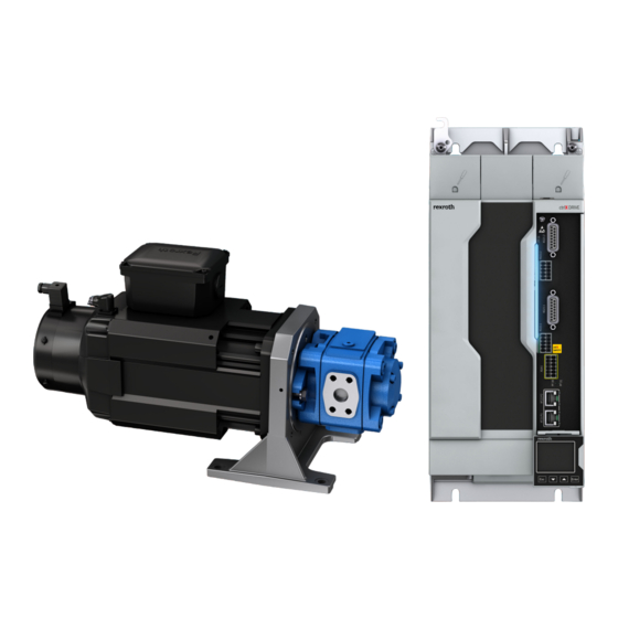
Page 24: Overview Of Components
RE 20135) or axial piston pump type A10FZO (see data sheet RE 91485) 2 Synchronous servo motor (M2SN with self-cooling, external venting or water cooling) see Project Planning Manual R911347583) 3 Drive controller ctrlX DRIVE (see R911386579 Project Planning Manual) Bosch Rexroth AG RE 62312-B, 03.2022... -
Page 25: Single-Axis Converter Xcs
R = Integrated braking transistor/braking resistor (XCS ≤ W0070) ⑥ Connector set: N = Without motor connector set ⑦ Control section: 01 = ctrlX DRIVE 02 = ctrlX DRIVE plus ⑧ Panel: N = Without panel A = With panel RE 62312-B, 03.2022 Bosch Rexroth AG... - Page 26 S = DRIVE Runtime System Extension (required for SvP) ⑳ Scope of functions, SafeMotion: 0 = Hardware option 1 ≠ SafeMotion 3 = SafeMotion Speed 5 = SafeMotion Position Other design: NN = None Bosch Rexroth AG RE 62312-B, 03.2022...
-
Page 27: Panel Xdp1 (Optional)
④ Other designs: NN = None ⑤ Panel firmware version: VS = Current version ⑥ Panel firmware release: RS = Current release ⑦ Export licenses required: NN = no ⑧ Other: NN = None RE 62312-B, 03.2022 Bosch Rexroth AG... - Page 28 (CP-XDP1) ● 32 × 12 mm: Panel ordered as individual component (XDP1-N-128-NN- VRSN-NN; R911403470) Nameplate (32 × 12 mm): 1: QR code 2: Type 3: Material number 4: Hardware index 5: Serial number Bosch Rexroth AG RE 62312-B, 03.2022...
-
Page 29: Motor-Pump Group Mpa02
This results in a particularly compact solution, which also offers advantages in terms of dynamics. Further information on the motor pump group can be found in operating instructions R911387041. RE 62312-B, 03.2022 Bosch Rexroth AG... -
Page 30: Pressure Transducer
4..20 mA. If you wish to use a pressure transducer for 4..20 mA, you require a DA extension. Identification of the product 5.4.1 Plates on the drive controller Positions of the plates Table 8: Positions of the plates Warning labels Type plate Additional plate Bosch Rexroth AG RE 62312-B, 03.2022... - Page 31 17 Supply input data 18 Rated voltage Input voltage 19 Rated current Input current Additional plate Table 10: Additional plate 1 QR code 2 Type designation 3 Material number 4 Hardware index 5 Serial number RE 62312-B, 03.2022 Bosch Rexroth AG...
-
Page 32: Nameplate Of The Motor Pump Group Mpa02
Table 11: C-UL listing ● UL standard: 61800-5-1 ● CSA standard: Canadian Standard CSA C22.2 No. 274-17 Company Name BOSCH REXROTH AG ⮫ https://productiq.ulprospector.com/en/profile/ 3453329/nmms7.e134201?term=NMMS7&page=12 Category Name: ● Power Conversion Equipment ● Transformers, General Purpose - Component File numbers Components ctrlX DRIVE: ●... -
Page 33: Customer Testing
Before subjecting a system or machine, in which these components are used, to a voltage test or a test of insu- lation resistance: Disconnect all connections of the Rexroth components or unplug plug-in connections to protect electronic ele- ments. RE 62312-B, 03.2022 Bosch Rexroth AG... - Page 34 Sytronix SvP 7030 IMC 34 / 186 Customer testing Bosch Rexroth AG RE 62312-B, 03.2022...
-
Page 35: Transport And Storage
Please observe the following classification limitations: ● Transport temperature range -20 ... +80 °C ● Relative humidity of air max. 75 % (at +30 °C) ● No occurrence of salt mist ● Observe the transport instructions on the packaging. RE 62312-B, 03.2022 Bosch Rexroth AG... -
Page 36: Handling The Motor-Pump Unit With Cranes Or Similar Lifting Gear
● Always fasten the lifting means at 2 lifting points at the motor-pump unit. Never lift the motor-pump unit at one lifting point only. ● Slowly and carefully lift and lower the motor-pump unit. Fig. 6: Handling MPA02 Bosch Rexroth AG RE 62312-B, 03.2022... -
Page 37: Weight Of Motor-Pump Units
Table 19: Ambient and operating conditions - transport Designation Symbol Unit Value Temperature range °C -25 … +70 a_tran Relative humidity 5 … 95 Absolute humidity 1 … 60 Climatic category (IEC721) Moisture condensation Not permitted Icing Not permitted RE 62312-B, 03.2022 Bosch Rexroth AG... -
Page 38: Storing Sytronix Systems
Additional measures must be taken on commissioning to preserve proper func- tioning – irrespective of the storage time which may be longer than the war- ranty period of our products. However, this does not involve any additional warranty claims. Bosch Rexroth AG RE 62312-B, 03.2022... - Page 39 Replace the shaft seal if a storage period of 24 months is exceeded. As a precaution, we recommend that you have the pump checked and the seals replaced by a Rexroth service after the maximum storage period has expired! RE 62312-B, 03.2022 Bosch Rexroth AG...
-
Page 40: Installation
(e.g. tank) using elastic elements. ● Make certain that the suction line, case drain line, and return line flow into the tank below the minimum fluid level in all operational states. Bosch Rexroth AG RE 62312-B, 03.2022... -
Page 41: Compatibility With Foreign Substances
Cleaning agents must not penetrate the hydraulic system. 7.3.2 Compatibility with foreign substances All drives and controls from Bosch Rexroth are developed and manufactured according to the state of the art. However, since it is impossible to pursue the continuing further development of all substances with which the drives and controls may get into contact (e.g. -
Page 42: Connecting Svp 7030 Hydraulically
The ports and mounting threads are rated for the operating pressures specified in the data sheet. The machine or system manufacturer must ensure that the connecting elements and lines comply with the specified operating conditions (pressure, flow, hydraulic fluid, temperature) with the necessary safety factors. Bosch Rexroth AG RE 62312-B, 03.2022... - Page 43 Fig. 8: Improperly installed suction line Fig. 9: Improperly laid suction and return line To minimize risk due to air pockets you should do without long, horizontally installed suction lines. RE 62312-B, 03.2022 Bosch Rexroth AG...
- Page 44 Mechanical installation of the motor-pump unit Fig. 10: Risk due to air pockets Moreover, improperly installed suction lines can be a cause of noise generation. Fig. 11: Noise sources A further important point is the proper connection. Bosch Rexroth AG RE 62312-B, 03.2022...
- Page 45 Sytronix SvP 7030 IMC 45 / 186 Mechanical installation of the motor-pump unit Fig. 12: Connection Missing O-rings can lead to air ingress. Fig. 13: Assembly without O-rings RE 62312-B, 03.2022 Bosch Rexroth AG...
- Page 46 Keep the following distance for mounting the suction line in the tank. Fig. 14: Suction line in the tank The following figure shows an optimum connection in detail: Fig. 15: Optimized design The following figure illustrates the perfect condition for the laminar flow Bosch Rexroth AG RE 62312-B, 03.2022...
- Page 47 Sytronix SvP 7030 IMC 47 / 186 Mechanical installation of the motor-pump unit Piping Fig. 16: Laminar flow Fig. 17: Piping notes RE 62312-B, 03.2022 Bosch Rexroth AG...
- Page 48 48 / 186 Mechanical installation of the motor-pump unit Noise reduction Flexible mounting reduces vibration and noise. Fig. 18: Damping rail Fig. 19: Damping rail in the mounted condition Fig. 20: Elastic pipe fittings Bosch Rexroth AG RE 62312-B, 03.2022...
- Page 49 ● pipes and flexible hoses and every combination of connecting pieces, couplings or connecting points with flexible hoses or pipes have been inspected by a technically qualified person for their safe working condi- tion. RE 62312-B, 03.2022 Bosch Rexroth AG...
-
Page 50: Mounting The Machine Control Cabinet Components
● Maintain the filters regularly in accordance with the dust load in the sur- roundings. ● Change the filters only while the fan is switched off, since otherwise the dissolving dirt is aspired by the fan and gets inside the control cabinet. Bosch Rexroth AG RE 62312-B, 03.2022... - Page 51 NOTICE Risk of damage to the components! Only operate the components in their allowed installa- tion orientation. Allowed mounting orientation of the components Only the mounting orientation G1 is allowed for ctrlX DRIVE components. RE 62312-B, 03.2022 Bosch Rexroth AG...
- Page 52 This avoids the generation of pockets of heat in the component. 180° to normal mounting orientation 90° to normal mounting orientation Bottom mounting; mounting surface on bottom of control cabinet Top mounting; mounting surface at top of control cabinet Bosch Rexroth AG RE 62312-B, 03.2022...
-
Page 53: Single-Axis Converter Xcs*-W0023
Reduction of P DC_cont at T < T < T out_cont a_work a_work_red Allowed mounting orientation Cooling type Forced ventilation Volumetric capacity of forced cooling Allowed switching frequencies 4 … 16 RE 62312-B, 03.2022 Bosch Rexroth AG... - Page 54 (0 mm) between the touch guard plates, and below the touch guard plates there is a distance of 3 mm (2 × 1.5 mm) Distance top Distance bottom Distance horizontal Bosch Rexroth AG RE 62312-B, 03.2022...
-
Page 55: Single-Axis Converter Xcs*-W0054
Symbol Unit XCS*-W0054 Weight Device height Device depth 196.5 Device width Insulation resistance at 500 V DC MOhm Capacitance against housing 2 × 100 1) 2) 3) Housing dimension; see also related dimensional drawing RE 62312-B, 03.2022 Bosch Rexroth AG... - Page 56 (0 mm) between the touch guard plates, and below the touch guard plates there is a distance of 3 mm (2 × 1.5 mm) Distance top Distance bottom Distance horizontal Bosch Rexroth AG RE 62312-B, 03.2022...
-
Page 57: Single-Axis Converter Xcs*-W0070
Symbol Unit XCS*-W0070 Weight Device height Device depth 196.5 Device width Insulation resistance at 500 V DC MOhm Capacitance against housing 2 × 100 1) 2) 3) Housing dimension; see also related dimensional drawing RE 62312-B, 03.2022 Bosch Rexroth AG... - Page 58 (0 mm) between the touch guard plates, and below the touch guard plates there is a distance of 3 mm (2 × 1.5 mm) Distance top Distance bottom Distance horizontal Bosch Rexroth AG RE 62312-B, 03.2022...
-
Page 59: Single-Axis Converter Xcs*-W0100
Unit XCS*-W0100 Weight 10.3 Device height Device depth 196.5 Device width Insulation resistance at 500 V DC MOhm Capacitance against housing 2 × 100 1) 2) 3) Housing dimension; see also related dimensional drawing RE 62312-B, 03.2022 Bosch Rexroth AG... - Page 60 (0 mm) between the touch guard plates, and below the touch guard plates there is a distance of 3 mm (2 × 1.5 mm) Distance top Distance bottom Distance horizontal Bosch Rexroth AG RE 62312-B, 03.2022...
-
Page 61: Single-Axis Converter Xcs*-W0120
Unit XCS*-W0120 Weight 10.3 Device height Device depth 196.5 Device width Insulation resistance at 500 V DC MOhm Capacitance against housing 2 × 100 1) 2) 3) Housing dimension; see also related dimensional drawing RE 62312-B, 03.2022 Bosch Rexroth AG... - Page 62 (0 mm) between the touch guard plates, and below the touch guard plates there is a distance of 3 mm (2 × 1.5 mm) Distance top Distance bottom Distance horizontal Bosch Rexroth AG RE 62312-B, 03.2022...
-
Page 63: Single-Axis Converter Xcs*-W0150
Symbol Unit XCS*-W0150 Weight Device height Device depth 196.5 Device width Insulation resistance at 500 V DC MOhm Capacitance against housing 2 × 100 1) 2) 3) Housing dimension; see also related dimensional drawing RE 62312-B, 03.2022 Bosch Rexroth AG... - Page 64 (0 mm) between the touch guard plates, and below the touch guard plates there is a distance of 3 mm (2 × 1.5 mm) × Distance top Distance bottom Distance horizontal Bosch Rexroth AG RE 62312-B, 03.2022...
-
Page 65: Single-Axis Converter Xcs*-W0180
Symbol Unit XCS*-W0180 Weight Device height Device depth 196.5 Device width Insulation resistance at 500 V DC MOhm Capacitance against housing 2 × 100 1) 2) 3) Housing dimension; see also related dimensional drawing RE 62312-B, 03.2022 Bosch Rexroth AG... - Page 66 (0 mm) between the touch guard plates, and below the touch guard plates there is a distance of 3 mm (2 × 1.5 mm) Distance top Distance bottom Distance horizontal Bosch Rexroth AG RE 62312-B, 03.2022...
-
Page 67: Single-Axis Converter Xcs*-W0210
Unit XCS*-W0210 Weight Device height 340.5 Device depth 196.5 Device width Insulation resistance at 500 V DC MOhm Capacitance against housing 2 × 100 1) 2) 3) Housing dimension; see also related dimensional drawing RE 62312-B, 03.2022 Bosch Rexroth AG... - Page 68 (0 mm) between the touch guard plates, and below the touch guard plates there is a distance of 3 mm (2 × 1.5 mm) Distance top Distance bottom Distance horizontal Bosch Rexroth AG RE 62312-B, 03.2022...
-
Page 69: Single-Axis Converter Xcs*-W0250
Unit XCS*-W0250 Weight Device height 340.5 Device depth 196.5 Device width Insulation resistance at 500 V DC MOhm Capacitance against housing 2 × 100 1) 2) 3) Housing dimension; see also related dimensional drawing RE 62312-B, 03.2022 Bosch Rexroth AG... - Page 70 (0 mm) between the touch guard plates, and below the touch guard plates there is a distance of 3 mm (2 × 1.5 mm) Distance top Distance bottom Distance horizontal Bosch Rexroth AG RE 62312-B, 03.2022...
-
Page 71: Single-Axis Converter Xcs*-W0280
Unit XCS*-W0280 Weight Device height 340.5 Device depth 196.5 Device width Insulation resistance at 500 V DC MOhm Capacitance against housing 2 × 100 1) 2) 3) Housing dimension; see also related dimensional drawing RE 62312-B, 03.2022 Bosch Rexroth AG... - Page 72 (0 mm) between the touch guard plates, and below the touch guard plates there is a distance of 3 mm (2 × 1.5 mm) Distance top Distance bottom Distance horizontal Bosch Rexroth AG RE 62312-B, 03.2022...
-
Page 73: Braking Resistor Hlr01
Information on mains filters XNF and mains chokes XNL can be found in Project Planning Manual R911386579. In some cases, mains filters HNF01.x and mains chokes HNL01.x are used. Information on mains filters XNF and mains chokes XNL can be found in Project Planning Manual R911342564. RE 62312-B, 03.2022 Bosch Rexroth AG... -
Page 74: Connecting The Sytronix System Svp 7030 Electrically
SafeMotion. For these components please observe the mounting instructions in Project Planning Manual R911386579. Here you can also find notes on accessories such as connector sets, shield connections, DC bus adapters, touch guards and DC bus chokes. Bosch Rexroth AG RE 62312-B, 03.2022... -
Page 75: Input And Output Assignment At Drive Controller Ctrlx Drive
Input for selection of channel 2 xxx = measuring range in [bar] STO_CH2 -QA01 Mains contactor (optional) -RA01 Mains choke -RA02 External braking resistor -RF01 Mains filter (optional) Fig. 34: Overview of ctrlX DRIVE topology RE 62312-B, 03.2022 Bosch Rexroth AG... -
Page 76: Mains Connection
● The residual-current-operated circuit breaker is of type B (IEC 60755) ● Trip limit of the residual-current-operated circuit breaker is ≥ 300 mA ● Supplying TN-S mains ● Maximum length of motor cable 20 m, shielded ● An XNF mains filter is used Bosch Rexroth AG RE 62312-B, 03.2022... - Page 77 Connecting the Sytronix system SvP 7030 electrically ● Each residual-current-operated circuit breaker only supplies one drive con- troller ● Only Bosch Rexroth components and accessories including cables and filters are used Motor cable lengths Keep motor cables as short as possible. Only short motor cables make low leakage currents possible and thereby enable residual-current-operated circuit breakers to work.
- Page 78 Control circuit for the mains connection Fig. 36: Control circuit for the mains connection Optional Bb relay contact CNC Lag error message of control unit Fuse of power supply Fuse of 24 V power supply unit Bosch Rexroth AG RE 62312-B, 03.2022...
-
Page 79: Control Voltage
The tables below contain the individual power values required by the drive con- troller. The power requirement of the supplying 24V power supply unit results from the sum of these individual power values. RE 62312-B, 03.2022 Bosch Rexroth AG... - Page 80 The power consumption is specified as the maximum value of the respective component and can occur at individual components . In drive packages with several components, the occurring power consumption under statistical assumptions will be lower than the calculated one. Bosch Rexroth AG RE 62312-B, 03.2022...
- Page 81 ● For looping through the control voltage, observe the maximum current car- rying capacity of the connection points. The maximum current carrying capacity limits the number of devices to which the control voltage can be looped through. RE 62312-B, 03.2022 Bosch Rexroth AG...
- Page 82 You are only allowed to loop through the control voltage between the compo- nents, if the sum of current consumptions ΣI of the individual components is smaller than the current carrying capacity of the connection point. Bosch Rexroth AG RE 62312-B, 03.2022...
-
Page 83: Specification Of The Digital/Analog Inputs/Outputs
100 + position controller clock cycle Digital inputs (safety technology Safe Torque Off) The digital inputs comply with IEC 61131-2. Table 48: Digital inputs (safety technology) Datum Unit Min. Max. Allowed input voltage High Current consumption RE 62312-B, 03.2022 Bosch Rexroth AG... - Page 84 < 25 V. 3) The maximum energy content depends on the switching frequency f of out- puts Digital outputs (safety technology Safe Torque Off) The digital outputs are compatible with digital inputs IEC 61131-2. Bosch Rexroth AG RE 62312-B, 03.2022...
- Page 85 : Number of digital inputs that are used for a digital output Table 52: Time behavior Designation Unit Typ. Test pulse width (t μs Cycle duration (T Phase shift between two test ° pulses on both channels (φ) RE 62312-B, 03.2022 Bosch Rexroth AG...
- Page 86 Input resistance R kΩ Input bandwidth (-3 dB): Common-mode range Common-mode rejection Relative measuring error at 90 % in_work Resolution Cable In case of cable lengths > 30 m use shielded cables only. Bosch Rexroth AG RE 62312-B, 03.2022...
-
Page 87: Overall Connection Diagram Xcs*-W0023
XG21 Multi-encoder (optional) XD04 Internal/external braking resistor XG31 Digital inputs/outputs; analog input XD10 Control voltage XG4x Safety technology XF21, XF22 Communication XZ03 Motor, motor temperature moni- XG02 Ready-for-operation relay contact toring, motor holding brake RE 62312-B, 03.2022 Bosch Rexroth AG... -
Page 88: Overall Connection Diagram Xcs*-W0054/W0070
DC bus motor holding brake XD03 Motor XG20 Digital encoder XD04 External braking resistor XG21 Multi-encoder (optional) XD10 Control voltage XG31 Digital inputs/outputs; analog input XF21, XF22 Communication XG4x Safety technology XG02 Ready-for-operation relay contact Bosch Rexroth AG RE 62312-B, 03.2022... -
Page 89: Overall Connection Diagram Xcs*-W01Xx
DC bus motor holding brake XD03 Motor XG20 Digital encoder XD04 External braking resistor XG21 Multi-encoder (optional) XD10 Control voltage XG31 Digital inputs/outputs; analog input XF21, XF22 Communication XG4x Safety technology XG02 Ready-for-operation relay contact RE 62312-B, 03.2022 Bosch Rexroth AG... -
Page 90: Overall Connection Diagram Xcs*-W02Xx
DC bus motor holding brake XD03 Motor XG20 Digital encoder XD04 External braking resistor XG21 Multi-encoder (optional) XD10 Control voltage XG31 Digital inputs/outputs; analog input XF21, XF22 Communication XG4x Safety technology XG02 Ready-for-operation relay contact Bosch Rexroth AG RE 62312-B, 03.2022... -
Page 91: Electrical Data Of Single-Axis Converter Xcs*-W0023
Delta mains Tolerance U +10 / -15 Minimum inductance of mains supply (mains µH phase inductance) Inrush current L_trans_max_on Maximum allowed ON-OFF cycles per minute Mains input continuous current at U LN_nom (three-phase) DC_cont RE 62312-B, 03.2022 Bosch Rexroth AG... - Page 92 External braking resistor/integrated braking transistor Table 57: Minimum requirement on external braking resistor/integrated braking transistor Designation Symbol Unit XCS*-W0023 Minimum resistance 43.7 DC_Bleeder_min Maximum resistance DC_Bleeder_max Braking transistor continuous power Absorbable regenerative power of braking tran- R_max sistor Bosch Rexroth AG RE 62312-B, 03.2022...
-
Page 93: Electrical Data Of Single-Axis Converter Xcs*-W0054
Mains voltage, three-phase at Corner-grounded- Not permitted Delta mains Tolerance U +10 / -15 Minimum inductance of mains supply (mains µH phase inductance) Assigned mains choke type XNL1-1E-0362-N0080-B-500- NNNN-NN Inrush current L_trans_max_on Maximum allowed ON-OFF cycles per minute RE 62312-B, 03.2022 Bosch Rexroth AG... - Page 94 External braking resistor/integrated braking transistor Table 61: Minimum requirement on external braking resistor/integrated braking transistor Designation Symbol Unit XCS*-W0054 Minimum resistance DC_Bleeder_min Maximum resistance DC_Bleeder_max Braking transistor continuous power Absorbable regenerative power of braking tran- 2000 R_max sistor Bosch Rexroth AG RE 62312-B, 03.2022...
-
Page 95: Electrical Data Of Single-Axis Converter Xcs*-W0070
Mains voltage, three-phase at Corner-grounded- Not permitted Delta mains Tolerance U +10 / -15 Minimum inductance of mains supply (mains µH phase inductance) Assigned mains choke type XNL1-1E-0362-N0080-B-500- NNNN-NN Inrush current L_trans_max_on Maximum allowed ON-OFF cycles per minute RE 62312-B, 03.2022 Bosch Rexroth AG... - Page 96 Table 65: Minimum requirement on external braking resistor/integrated braking transistor Designation Symbol Unit XCS*-W0070 Minimum resistance DC_Bleeder_min Maximum resistance DC_Bleeder_max Braking transistor continuous power 10.3 Absorbable regenerative power of braking tran- 2000 R_max sistor Bosch Rexroth AG RE 62312-B, 03.2022...
-
Page 97: Electrical Data Of Single-Axis Converter Xcs*-W0100
Mains voltage, three-phase at Corner-grounded- Not permitted Delta mains Tolerance U +10 / -15 Minimum inductance of mains supply (mains µH phase inductance) Assigned mains choke type XNL1-1E-0362-N0080-B-500- NNNN-NN Inrush current L_trans_max_on Maximum allowed ON-OFF cycles per minute RE 62312-B, 03.2022 Bosch Rexroth AG... - Page 98 External braking resistor/integrated braking transistor Table 68: Minimum requirement on external braking resistor/integrated braking transistor Designation Symbol Unit XCS*-W0100 Minimum resistance DC_Bleeder_min Maximum resistance DC_Bleeder_max Braking transistor continuous power Absorbable regenerative power of braking tran- 2000 R_max sistor Bosch Rexroth AG RE 62312-B, 03.2022...
-
Page 99: Electrical Data Of Single-Axis Converter Xcs*-W0120
Mains voltage, three-phase at Corner-grounded- Not permitted Delta mains Tolerance U +10 / -15 Minimum inductance of mains supply (mains µH phase inductance) XNL1-1E-0362-N0080-B-500- Assigned mains choke type NNNN-NN Inrush current L_trans_max_on Maximum allowed ON-OFF cycles per minute RE 62312-B, 03.2022 Bosch Rexroth AG... - Page 100 External braking resistor/integrated braking transistor Table 71: Minimum requirement on external braking resistor/integrated braking transistor Designation Symbol Unit XCS*-W0120 Minimum resistance DC_Bleeder_min Maximum resistance DC_Bleeder_max Braking transistor continuous power Absorbable regenerative power of braking tran- 2000 R_max sistor Bosch Rexroth AG RE 62312-B, 03.2022...
-
Page 101: Electrical Data Of Single-Axis Converter Xcs*-W0150
Mains voltage, three-phase at Corner-grounded- Not permitted Delta mains Tolerance U +10 / -15 Minimum inductance of mains supply (mains µH phase inductance) XNL1-1E-0170-N0146-B-500- Assigned mains choke type NNNN-NN Inrush current L_trans_max_on Maximum allowed ON-OFF cycles per minute RE 62312-B, 03.2022 Bosch Rexroth AG... - Page 102 Table 74: Minimum requirement on external braking resistor/integrated braking transistor Designation Symbol Unit XCS*-W0150 Minimum resistance DC_Bleeder_min Maximum resistance DC_Bleeder_max Braking transistor continuous power 29.45 Absorbable regenerative power of braking tran- 2000 R_max sistor Bosch Rexroth AG RE 62312-B, 03.2022...
-
Page 103: Electrical Data Of Single-Axis Converter Xcs*-W0180
Mains voltage, three-phase at Corner-grounded- Not permitted Delta mains Tolerance U +10 / -15 Minimum inductance of mains supply (mains µH phase inductance) XNL1-1E-0170-N0146-B-500- Assigned mains choke type NNNN-NN Inrush current L_trans_max_on Maximum allowed ON-OFF cycles per minute RE 62312-B, 03.2022 Bosch Rexroth AG... - Page 104 Table 77: Minimum requirement on external braking resistor/integrated braking transistor Designation Symbol Unit XCS*-W0180 Minimum resistance DC_Bleeder_min Maximum resistance DC_Bleeder_max Braking transistor continuous power 35.5 Absorbable regenerative power of braking tran- 2000 R_max sistor Bosch Rexroth AG RE 62312-B, 03.2022...
-
Page 105: Electrical Data Of Single-Axis Converter Xcs*-W0210
Mains voltage, three-phase at Corner-grounded- Not permitted Delta mains Tolerance U +10 / -15 Minimum inductance of mains supply (mains µH phase inductance) XNL1-1E-0170-N0146-B-500- Assigned mains choke type NNNN-NN Inrush current L_trans_max_on Maximum allowed ON-OFF cycles per minute RE 62312-B, 03.2022 Bosch Rexroth AG... - Page 106 External braking resistor/integrated braking transistor Table 80: Minimum requirement on external braking resistor/integrated braking transistor Designation Symbol Unit XCS*-W0210 Minimum resistance DC_Bleeder_min Maximum resistance DC_Bleeder_max Braking transistor continuous power Absorbable regenerative power of braking tran- 5000 R_max sistor Bosch Rexroth AG RE 62312-B, 03.2022...
-
Page 107: Electrical Data Of Single-Axis Converter Xcs*-W0250
Mains voltage, three-phase at Corner-grounded- Not permitted Delta mains Tolerance U +10 / -15 Minimum inductance of mains supply (mains µH phase inductance) XNL1-1E-0170-N0146-B-500- Assigned mains choke type NNNN-NN Inrush current L_trans_max_on Maximum allowed ON-OFF cycles per minute RE 62312-B, 03.2022 Bosch Rexroth AG... -
Page 108: Required Electric Strength Of Connected Cables
– Lines run on the left or right side of the device have to be run at a minimum distance of d ≥ 10 mm to the device. If this distance is less than the minimum distance, these lines must have been designed for the mains voltage and DC bus voltage. Bosch Rexroth AG RE 62312-B, 03.2022... -
Page 109: Connection Points Power Section/Control Section
Sytronix SvP 7030 IMC 109 / 186 Connecting the Sytronix system SvP 7030 electrically Fig. 45: d : Lateral distance 7.5.20 Connection points power section/control section Power section (example XCS) Control section (example XCS) RE 62312-B, 03.2022 Bosch Rexroth AG... -
Page 110: Xcs, Connection Points
Bottom XD02: DC bus XD10: Control voltage XD01: Mains connection XG02: Ready-for-operation relay XD04: External braking resistor contact XG20: Digital encoder connec- tion XZ03: Motor connection + motor temperature monitoring and motor holding brake Bosch Rexroth AG RE 62312-B, 03.2022... - Page 111 XD02: DC bus XD10: Control voltage XD01: Mains connection XG02: Ready-for-operation relay XD03: Motor connection contact XD04: External braking resistor XG03: Motor temperature moni- toring and motor holding brake XG20: Digital encoder connec- tion RE 62312-B, 03.2022 Bosch Rexroth AG...
- Page 112 XD02: DC bus XD10: Control voltage XD01: Mains connection XG02: Ready-for-operation relay XD03: Motor connection contact XD04: External braking resistor XG03: Motor temperature moni- toring and motor holding brake XG20: Digital encoder connec- tion Bosch Rexroth AG RE 62312-B, 03.2022...
-
Page 113: Connection Points Of Control Section
T0 = Safe Torque Off (STO) M5 = SafeMotion (M5) ⑪ Option 2: EC = Multi-encoder interface NN = Not equipped ⑫ Option 3: ET = Multi-Ethernet DA = Digital/analog I/O extension NN = Not equipped RE 62312-B, 03.2022 Bosch Rexroth AG... - Page 114 ✓ ✓ NN = Not equipped Option 3 ET = Multi-Ethernet ✓ DA = Digital/analog I/O extension ✓ ✓ NN = Not equipped ✓ ✓ Option Com. ET = Multi-Ethernet X3 = ctrlX CORE Bosch Rexroth AG RE 62312-B, 03.2022...
- Page 115 XF21, XF22: Communication ctrlX DRIVEplus single-axis Table 91: Connection points XG21: Multi-encoder; optional XG31: Digital inputs/outputs, analog inputs XG41: Safety technology (Safe Torque Off); optional XG42, XG43, XG44: Safety technology (SafeMotion M5); optional XF21, XF22: Communication RE 62312-B, 03.2022 Bosch Rexroth AG...
-
Page 116: On-Board Connection Points
Additionally, mount the housing on a bare metal mounting plate. Connect the mounting plate also to the equipment grounding system in the control cabinet using at least the same cross-section. Bosch Rexroth AG RE 62312-B, 03.2022... - Page 117 2) Connection of equipment grounding conductor XCS*-W0100/120 Connect ring cable lugs M5 of equipment grounding conductors to the device housing ( symbol). Tightening torque: 4.5 Nm Fig. 47: Connection points of grounding conductor 1 Mains 2 Motor RE 62312-B, 03.2022 Bosch Rexroth AG...
- Page 118 Tightening torque: 8 Nm Fig. 48: Connection point of equipment grounding conductor (XCS*-W02xx) XCS*-W0150/180 Connect ring cable lugs M6 of equipment grounding conductors to the device housing ( symbol). Tightening torque: 4 … 5 Nm Bosch Rexroth AG RE 62312-B, 03.2022...
-
Page 119: Connection Points Of The Components
The connector is included in the scope of delivery Overview There are different types of connections: ● Screw connection at device ( ● Screw connection at connector ( ● Spring terminal at connector ( RE 62312-B, 03.2022 Bosch Rexroth AG... - Page 120 Connection to power grid (L1) Connection to power grid (L2) Connection to power grid (L3) Connection of equipment grounding conductor Screw connection at connector Unit min. max. Connection cable 16.0 stranded wire Stripped length Tightening torque Bosch Rexroth AG RE 62312-B, 03.2022...
- Page 121 Identifi- Function cation Connection to power grid (L1) Connection to power grid (L2) Connection to power grid (L3) Terminal block Unit min. max. Screw thread Tightening torque Connection cable 1×50 stranded wire 2×25 1×1/0 RE 62312-B, 03.2022 Bosch Rexroth AG...
- Page 122 XD02, L+ L -, DC bus connection Function, pinout The DC bus connection connects ● multiple drive controllers to one another ● one drive controller to a DC bus capacitor unit (to backup the DC bus voltage) Bosch Rexroth AG RE 62312-B, 03.2022...
- Page 123 Fig. 50: Swivel hooks for DC bus connection Tightening torque 2.8 Nm Short-circuit protection By fusing elements in the incoming cir- cuit of the mains connection Overload protection Current carrying capacity ≤ W0120: 120 A ≥ W0150: 300 A RE 62312-B, 03.2022 Bosch Rexroth AG...
- Page 124 The touch guard plate may only be removed to connect the DC buses of neigh- boring devices. Dismounting the touch guard Unlock and open the touch guard flap. Move the touch guard plate vertically upwards and remove it. Bosch Rexroth AG RE 62312-B, 03.2022...
- Page 125 See chapter “DC bus coupling” in document R911386579. XD03: Motor connection Installation instructions The specified connection cross sections are the cross sections that can be connected. Size the required cross-section of the connection lines according to the occurring current load. RE 62312-B, 03.2022 Bosch Rexroth AG...
- Page 126 For power connection V1 at motor For power connection W1 at motor For equipment grounding connection at motor Screw connection at connector Unit min. max. Connection cable 0.75 10.0 stranded wire Stripped length Tightening torque Bosch Rexroth AG RE 62312-B, 03.2022...
- Page 127 Table 100: Function, pin assignment, properties View Labeling Function for power connection U1 at motor for power connection V1 at motor for power connection W1 at motor Connection block Unit min. max. Connection cables RE 62312-B, 03.2022 Bosch Rexroth AG...
- Page 128 1.5 … 4 mm² 6 … 10 mm² 16 mm² with twin wire end fer- AWG16 … 12 AWG10 … 8 AWG6 rule 2 × 1.5 … 6 mm² without wire end ferrule AWG16 … 10 Bosch Rexroth AG RE 62312-B, 03.2022...
- Page 129 (dismounting: see below). essary part of the cable feed- ● Remove unnecessary part of through (e.g., using diagonal the cable feedthrough (e.g., cutters). using diagonal cutters). ● Mount cable feedthrough with ∅15,5 opening width. RE 62312-B, 03.2022 Bosch Rexroth AG...
- Page 130 For power connection U1 at motor For power connection V1 at motor For power connection W1 at motor Terminal block Unit min. max. Connection cable 1×50 stranded wire with ring cable lug 2×25 Bosch Rexroth AG RE 62312-B, 03.2022...
- Page 131 Accessories, shield connection: ● XCS*-W0210/250/280 – XAS2-004-001-NN – XAS2-004-002-N Typical motor cable cross section: ● 1 × 50 mm: ● Double wiring with 2 × 25 mm is possible using twin wire end ferrule. RE 62312-B, 03.2022 Bosch Rexroth AG...
- Page 132 ● Screw connection at device ( ● Screw connection at connector ( ● Spring terminal at connector ( XD04 XD04 XD04 Component W02xx: 35 mm W0100, W0120: 16 mm W0023, W0054, W0070: 10 mm W0150, W0180: 16 mm Bosch Rexroth AG RE 62312-B, 03.2022...
- Page 133 Connection cable 0.75 stranded wire Stripped length Tightening torque XD04 (35 mm Table 105: Function, pinout, properties View Marking Function Equipment grounding conductor Braking resistor Braking resistor Terminal block Unit min. max. Connection cable RE 62312-B, 03.2022 Bosch Rexroth AG...
- Page 134 Installation instructions Requirements for the connection to 24 V supply: ● Minimum cross-section: 1 mm ● Maximum allowed inductance: 100 µH (2 twisted single strands, 75 m long) ● Parallel line routing where possible Bosch Rexroth AG RE 62312-B, 03.2022...
- Page 135 The connection point complies with IEEE 802.3 standard. P1, P2 P1 means port 1 and P2 means port 2 etc.. Thus, the error counter of the firmware can be directly assigned to a port. RE 62312-B, 03.2022 Bosch Rexroth AG...
- Page 136 0.19 m; 0.25 m; 0.35 m; 0.55 m; 1 m; 1.25 m; 2 m; 3 m; 5 m; 7 Order code for a cable with a length of 0.55 m: RKB0013/00,55 Minimum bending radius: 30.75 mm Bosch Rexroth AG RE 62312-B, 03.2022...
- Page 137 Excess voltage at the input (e.g., by the motor winding voltage flashing over) can get to the housing. Make sure that the temperature sensor of the connected motor is double-insulated from the motor winding. RE 62312-B, 03.2022 Bosch Rexroth AG...
- Page 138 XZ03 (1.5 mm Component 0100…W0280 0054…0090 0023 1) Hybrid connection (motor, motor temperature monitoring and motor holding brake) 2) Connectors included in the scope of delivery 3) Connectors not in the scope of delivery. Bosch Rexroth AG RE 62312-B, 03.2022...
- Page 139 Make sure to comply with the required minimum current consumption of 100 mA when using an external contact element. Otherwise, the brake current monitoring function will signal an error. RE 62312-B, 03.2022 Bosch Rexroth AG...
- Page 140 XG03 Time constant of load Number of switching actions at Wear-free electronic contact maximum time constant of load Switching frequency Short-circuit protection XG03.7 against XG03.8 (output for controlling the motor holding brake) Overload protection Bosch Rexroth AG RE 62312-B, 03.2022...
- Page 141 Only the allowed control voltage for the device is allowed at the motor temperature evaluation input. Excess voltage at the input may damage the device. Connectors not included in scope of delivery. RE 62312-B, 03.2022 Bosch Rexroth AG...
- Page 142 Push the connector in the plug-in direction. Unplug the connector. Encoder connection with hybrid cables Hybrid cables (e.g., RHB2-021DDB) connect the drive controller to the motor (XZ03) and encoder (XG20). Bosch Rexroth AG RE 62312-B, 03.2022...
- Page 143 Table 113: Function, properties View Identi- Function fica- tion XG21 Motor encoder connection D-Sub, 15-pin, female Unit min. max. Connection cable 0.25 stranded wire Type of encoder evaluation Connectors/cables not included in scope of delivery. RE 62312-B, 03.2022 Bosch Rexroth AG...
- Page 144 The type code of the motor shows whether or not the encoder system supports the single-turn (xS) or multi-turn (xM) functionality. Example: The MS2N04- D0BHN-CSDH0-NNNN-NN motor is equipped with an ACURO®link single-turn encoder system. Bosch Rexroth AG RE 62312-B, 03.2022...
- Page 145 Cable length The maximum allowed cable length depends on multiple factors and is described in chapter “Encoder cable length" in document R911386579. HIPERFACE® (12 V supply voltage) Fig. 56: HIPERFACE® encoder system connection diagram RE 62312-B, 03.2022 Bosch Rexroth AG...
- Page 146 Table 115: 12 V voltage supply Datum Unit min. typ. max. Voltage for encoder supply 10.7 12.3 Output current 1) The sum of the power consumptions of all connected encoder systems should not exceed 12 W. Bosch Rexroth AG RE 62312-B, 03.2022...
- Page 147 Fig. 58: Maximum allowed encoder cable lengths for 12 V encoder systems depending on the line cross-section at 10 V supply voltage I [mA] Encoder current consumption l [m] Cable length 0.5 mm ; 1.0 mm Line cross sections RE 62312-B, 03.2022 Bosch Rexroth AG...
- Page 148 The cross section of lines for the supply voltage has to be 0.5 mm at minimum. Allowed encoder cable length for resolver encoder systems Maximum 75 m (The cross-section of lines for the supply voltage has to be 0.5 mm at min- imum.) Bosch Rexroth AG RE 62312-B, 03.2022...
- Page 149 Analog input of drive controller. Only connect the inner shield of the con- nection cable to the drive controller if GND has not been connected to ground in the external device. External device Inner shield of the connection cable OS Overall shield of the connection cable RE 62312-B, 03.2022 Bosch Rexroth AG...
- Page 150 1) IO: Input/output; I: Input; O: Output The technical data can be found in document R911386579. Table 120: Properties Spring terminal (connector) Unit min. max. Connection cable stranded wire Stripped length Connectors included in scope of delivery. Bosch Rexroth AG RE 62312-B, 03.2022...
- Page 151 Analog input of drive controller. Only connect the inner shield of the con- nection cable to the drive controller if GND has not been connected to ground in the external device. External device Inner shield of the connection cable OS Overall shield of the connection cable RE 62312-B, 03.2022 Bosch Rexroth AG...
- Page 152 External device. Only connect the inner shield of the connection cable to the external device if GND has not been connected to ground in the external device. Inner shield of the connection cable OS Overall shield of the connection cable Bosch Rexroth AG RE 62312-B, 03.2022...
- Page 153 Spring terminal (con- Unit min. max. nector) Connection cable stranded wire Stripped length Connectors included in scope of delivery. Fig. 63: Example of dual-channel wiring Further wiring examples can be found in Application Manual R911383774. RE 62312-B, 03.2022 Bosch Rexroth AG...
- Page 154 Sytronix SvP 7030 IMC 154 / 186 Connecting the Sytronix system SvP 7030 electrically Bosch Rexroth AG RE 62312-B, 03.2022...
-
Page 155: Commissioning
Initial commissioning When carrying out any work in conjunction with commissioning of the Sytronix system, observe the general safety instructions and intended use in chapter 2 “Safety instructions“. RE 62312-B, 03.2022 Bosch Rexroth AG... -
Page 156: Filling The Sytronix System
If the shaft cannot be seen, operate the pump in the jog mode to see, whether pressure builds up (display in Indra- Works) ● If pressure builds up, check the direct functions/movements on the basis of a hydraulic circuit diagram. Bosch Rexroth AG RE 62312-B, 03.2022... -
Page 157: Commissioning Of The Drive Controller
● Air in the hydraulic system ● Water in the hydraulic system ● Aged hydraulic fluid ● Other contamination For recommissioning proceed as described in "Initial commissioning" above. RE 62312-B, 03.2022 Bosch Rexroth AG... - Page 158 Sytronix SvP 7030 IMC 158 / 186 Recommissioning after standstill Bosch Rexroth AG RE 62312-B, 03.2022...
-
Page 159: Operation
If an error or a warning occurs, eliminate the cause of error. Then you can acknowledge the error message as follows: ● Press the [ESC] key ● Set digital input 5 at XG31.7 to high level LED PF01 (device state) PF01 LED RE 62312-B, 03.2022 Bosch Rexroth AG... - Page 160 Descriptions of colors and flashing patterns: See documentation for firmware ctrlX DRIVE, Diagnostic Messages of Runtime AXS, Reference Book (R911383776) or Diagnostic Messages of the Runtime AXS-V-03VRS (R911409808). Bosch Rexroth AG RE 62312-B, 03.2022...
-
Page 161: Sercos/Ethercat
Connection to network available with telegram exchange (EtherCAT bus active) Flashing green Sercos Table 126: Port LED LED: Color / flashing Meaning pattern No connection No data transmission Data transmission running Permanently lit yellow Connection to network available Permanently lit green RE 62312-B, 03.2022 Bosch Rexroth AG... -
Page 162: Diagnostic Led
CP1 (communication phase 1 active) flashing orange/green CP2 (communication phase 2 active) flashing orange/green CP3 (communication phase 3 active) flashing orange/green CP4 (communication phase 4 active) Permanently lit green HP0 (hot-plug phase 0 active) flashing orange/green Bosch Rexroth AG RE 62312-B, 03.2022... - Page 163 RD = LED permanently lit red, -- = LED is off 2) Display priority (1 = highest priority); the state of the highest priority is displayed 3) NRT = None Real Time 4) MST = Master synchronization telegram RE 62312-B, 03.2022 Bosch Rexroth AG...
- Page 164 Sytronix SvP 7030 IMC 164 / 186 Sercos/EtherCAT Bosch Rexroth AG RE 62312-B, 03.2022...
-
Page 165: Maintenance And Repair
The electrical components are maintenance-free. 10.4 Repair Rexroth offers a comprehensive range of services for repairing Rexroth Sytronix systems. Repairs of the Sytronix system may only be performed by authorized, skilled and instructed staff. RE 62312-B, 03.2022 Bosch Rexroth AG... -
Page 166: Spare Parts
On some components, the material number is shown on a name- plate or a label. Please address all questions regarding spare parts to your responsible Rexroth Service partner. Bosch Rexroth AG Service Industriehydraulik Bürgermeister-Dr.-Nebel-Straße 8 97816 Lohr am Main Germany Telephone +49 (0) 9352/40 50 60 E-mailservice@boschrexroth.de... -
Page 167: Decommissioning
The Sytronix system is a component that does not require decommissioning. For this reason, this chapter of the present instructions does not contain any information. How to demount and replace your Sytronix system is described in the chapter “Demounting and replacement“ below. RE 62312-B, 03.2022 Bosch Rexroth AG... - Page 168 Sytronix SvP 7030 IMC 168 / 186 Bosch Rexroth AG RE 62312-B, 03.2022...
-
Page 169: Demounting And Replacement
Demount the Sytronix system. Use suitable lifting gear for this. Drain the Sytronix system completely. Plug all openings. 12.4 Preparing the components for storage or further use Proceed as described in ⮫ Chapter 6 “Transport and storage” on page 35. RE 62312-B, 03.2022 Bosch Rexroth AG... - Page 170 Sytronix SvP 7030 IMC 170 / 186 Preparing the components for storage or further use Bosch Rexroth AG RE 62312-B, 03.2022...
-
Page 171: Environmental Protection And Disposal
However, this requires that the products be free of oil, grease or other dirt. Furthermore, the products returned for disposal may not contain any undue foreign material or foreign components. Send the components free domicile to the following address: Bosch Rexroth AG Service Industriehydraulik Bürgermeister-Dr.-Nebel-Straße 8 D-97816 Lohr am Main Packaging Packaging materials consist of cardboard, plastics, wood or polystyrene. - Page 172 Plastic parts of the products may contain flame retardants. These plastic parts are labeled according to EN ISO 1043. They have to be recycled separately or disposed of according to the applicable legal provisions. Bosch Rexroth AG RE 62312-B, 03.2022...
-
Page 173: Troubleshooting
Unfavorable place of installa- Change place of installation (e.g. tion/mounting technique for the suspended mounting, no minimess pressure transducer line, no throttling point between pump and pressure transducer) RE 62312-B, 03.2022 Bosch Rexroth AG... - Page 174 Replace Sytronix system, contact pump) Rexroth Service Pressure too low Actual pressure value acquisition Check actual pressure value in incorrectly configured IndraWorks and, if required, cor- rect configuration of actual pres- sure value acquisition Replace pressure transducer Bosch Rexroth AG RE 62312-B, 03.2022...
- Page 175 Inlet temperature at Sytronix Inspect system, e.g. for malfunction ture too high system too high of the cooler, insufficient hydraulic fluid in the tank Wear of Sytronix system Replace control system, contact Rexroth Service RE 62312-B, 03.2022 Bosch Rexroth AG...
- Page 176 Sytronix SvP 7030 IMC 176 / 186 Fault table Bosch Rexroth AG RE 62312-B, 03.2022...
-
Page 177: Service And Support
● Details on the nameplate of the affected products, especially type code and serial number ● Your contact details (phone and fax number, e-mail address) Headquarters Bosch Rexroth AG Zum Eisengießer 1 97816 Lohr am Main Telephone: +49 (0) 9352/18-0 E-Mail: my.support@boschrexroth.com... - Page 178 Sytronix SvP 7030 IMC 178 / 186 Bosch Rexroth AG RE 62312-B, 03.2022...
-
Page 179: Index
......50 Single-axis converter XCS*-W0180..103 Control circuit for the mains connection..78 RE 62312-B, 03.2022 Bosch Rexroth AG... - Page 180 Single-axis converter XCS*-W0180..104 Mains filter XNF......73 Bosch Rexroth AG RE 62312-B, 03.2022...
- Page 181 ......104 Mains voltage..... . 103 RE 62312-B, 03.2022 Bosch Rexroth AG...
- Page 182 Weight of motor-pump units....37 Digital inputs, digital outputs..150 XG38 analog inputs, analog outputs..151 Bosch Rexroth AG RE 62312-B, 03.2022...
- Page 183 Sytronix SvP 7030 IMC 183 / 186 XG41 Safe Torque Off..... 153 RE 62312-B, 03.2022 Bosch Rexroth AG...
- Page 184 Sytronix SvP 7030 IMC 184 / 186 Bosch Rexroth AG RE 62312-B, 03.2022...
- Page 185 Sytronix SvP 7030 IMC 185 / 186 RE 62312-B, 03.2022 Bosch Rexroth AG...
- Page 186 Bosch Rexroth AG Zum Eisengießer 1 97816 Lohr a.Main Germany Tel. +49 9352 18-0 www.boschrexroth.com RE 62312-B RE 62312-B...