ABB FENA-01 User Manual
Ethernet adapter module
Hide thumbs
Also See for FENA-01:
- User manual (388 pages) ,
- Protocol manual (52 pages) ,
- Hardware manual (24 pages)

Related Manuals for ABB FENA-01


Summary of Contents for ABB FENA-01
- Page 1 — OPTIONS FOR ABB DRIVES, CONVERTERS AND INVERTERS FENA-01/-11/-21 Ethernet adapter module User’s manual...
- Page 2 Internet. See section Document library on the Internet on the inside of the back cover. For manuals not available in the Document library, contact your local ABB representative. The code below opens an online listing of the manuals applicable to the...
- Page 3 User’s manual FENA-01/-11/-21 Ethernet adapter module Table of contents 1. Safety instructions 4. Mechanical installation 5. Electrical installation Modbus/TCP protocol EtherNet/IP protocol PROFINET IO protocol NONE protocol selection 3AUA0000093568 Rev E 2018 ABB Oy All Rights Reserved. EFFECTIVE: 2018-03-14...
-
Page 5: Table Of Contents
Example topology of the Ethernet link ....38 FENA-01/-11/-21 Ethernet adapter module ....40... - Page 6 Parameter setting examples – ACS355 ....68 Speed and torque control using the ABB Drives – Enhanced communication profile ....68 Starting up fieldbus communication for ACSM1 drives .
- Page 7 Communication profiles ....... 89 ABB Drives communication profile ..... . . 91 Control word and Status word .
- Page 8 Communication profiles ......102 ABB Drives profile - Classic ......103 ABB Drives profile - Enhanced .
- Page 9 Table of contents Speed control using the ODVA AC/DC drive profile, Extended speed control assembly ....143 Starting up fieldbus communication for ACS480, ACS580 and ACS880 drives .
- Page 10 Torque Actual (AC/DC drive object) ....183 ABB Drives communication profile ..... . 184 Control word and Status word .
- Page 11 ......209 ABB Drives profile with set speed and set torque assembly ....... . 211 ABB Drives profile with set speed and set torque plus drive parameters assembly .
- Page 12 PROFINET IO connection configuration ....264 FENA-01/-11/-21 configuration parameters – group A (group 1) ........265 FENA-01/-11/-21 configuration parameters –...
- Page 13 Downloading the GSD file ......304 Configuring an ABB AC500 PLC ....304 Configuring a Siemens SIMATIC S7 PLC .
- Page 14 Actual values in positioning mode (ACSM1 only)..352 ABB Drives communication profile ..... . 353 Control word and Status word ..... . 353 Control word contents.
- Page 15 Table of contents PROFINET network settings ......363 PROFINET IO in FENA ......364 Cyclic message types .
- Page 16 Contents of this chapter ......415 FENA-01/-11/-21 ........415 Ethernet link .
- Page 17 Table of contents 22. Appendix B – ABB IP configuration tool for FENA Contents of this chapter ......431 Installation .
- Page 18 18 Table of contents...
-
Page 19: Safety Instructions
Safety instructions Safety instructions Contents of this chapter The chapter contains the warning symbols used in this manual and the safety instructions which you must obey when you install or connect an optional module to a drive, converter or inverter. If you ignore the safety instructions, injury, death or damage can occur. -
Page 20: Use Of Warnings
20 Safety instructions Use of warnings Warnings tell you about conditions which can cause injury or death, or damage to the equipment. They also tell you how to prevent the danger. The manual uses these warning symbols: Electricity warning tells you about hazards from electricity which can cause injury or death, or damage to the equipment. -
Page 21: Safety In Installation
Safety instructions Safety in installation These instructions are for all who install or connect an optional module to a drive, converter or inverter and need to open its front cover or door to do the work. WARNING! Obey these instructions. If you ignore them, injury or death, or damage to the equipment can occur. - Page 22 22 Safety instructions...
-
Page 23: Introduction To The Manual
Purpose of the manual The manual provides information on installing, commissioning and using the FENA-01/-11/-21 Ethernet adapter module. Applicability This manual applies to the FENA-01/-11/-21 Ethernet adapter module, software version 3.20 and later. Compatibility The FENA-01/-11/-21 Ethernet adapter module is compatible with different ABB drives and solar inverters. -
Page 24: Drives
24 Introduction to the manual Drives The table below shows the compatibility of FENA adapter module with different ABB drives. Drives FENA-01 FENA-11 FENA-21 ACS355 ACS380 ACSM1 ACS480 ACH580 ACQ580 ACS530* ACS560* ACS580 ACS850 ACS860* ACQ810 ACS880 ACS880-M04 check the compatibility in drive’s release note ... -
Page 25: Tools
Introduction to the manual In addition to Modbus/TCP, FENA-01/-11/-21 supports Modbus over UDP. In addition to these protocol, it is possible to have the no communication protocol running on FENA adapter module. This configuration is called NONE protocol. In this setup, FENA adapter module is used only for running Ethernet services which can be enabled/disabled via Web pages. -
Page 26: Target Audience
26 Introduction to the manual 50.21 FBA A timelevel sel and 50.51 FBA B timelevel sel is Slow or Monitoring. For more information on the Ethernet tool network, see: • Ethernet tool network for ACS880 drives application guide (3AUA0000125635) [English]) •... -
Page 27: Related Manuals
9AKK106930A3466 ACS880-17 (160 to 3200 kW) 9AKK106354A1499 ACS880-11 manuals ACS880-31 manuals ACS880-37 (132 to 355 kW) 9AKK106930A3467 ACS880-37 (160 to 3200 kW) 9AKK106354A1500 ACS880-M04 manuals 9AKK106930A7550 ACQ810 manuals 00598718 Option manuals and guides FENA-01/-11/-21 Ethernet adapter module user’s 3AUA0000093568 manual... -
Page 28: Contents
Safety instructions gives the safety instructions which you must obey when you install a fieldbus adapter module. • Overview of the Ethernet network and the FENA-01/-11/-21 module contains a short description of the Ethernet network and the adapter module. •... - Page 29 Introduction to the manual Modbus/TCP protocol • Modbus/TCP – Start-up presents the steps to take during the start-up of the drive with the adapter module and gives information on configuring the Modbus/TCP client. • Modbus/TCP – Communication profiles describes the communication profiles used in the communication between the client, the adapter module and the drive.
-
Page 30: Cybersecurity Disclaimer
ABB and its affiliates are not liable for damages and/or losses related to such security breaches, any unauthorized access, interference, intrusion, leakage and/or theft of data or information. -
Page 31: Terms And Abbreviations
This manual uses the term drive to refer converters and inverter as well. FENA-01/-11/-21 One of the optional fieldbus adapter modules Ethernet adapter available for ABB drives. FENA-01/-11/-21 is a device module through which an ABB drive is connected to an Ethernet network. Fieldbus adapter... -
Page 32: Abbreviations
32 Introduction to the manual Abbreviations Abbreviation Explanation DHCP Dynamic Host Control Protocol. A protocol for automating the configuration of IP devices. DHCP can be used to automatically assign IP addresses and related network information. Electromagnetic compatibility Fieldbus adapter Least significant bit Most significant bit Programmable logic controller... -
Page 33: Ethernet/Ip Terms And Abbreviations
ODVA™ ODVA stands for Open DeviceNet Vendor Association. ODVA is an independent organization that promotes interoperability between different manufacturers’ EtherNet/IP products. ABB is an Associate Member at ODVA. Output In the ODVA EtherNet/IP specification the word ‘output’ is used to describe data flow from the network into a... -
Page 34: Profinet Io Terms And Abbreviations
34 Introduction to the manual PROFINET IO terms and abbreviations Term Explanation Acyclic Communication in which messages are sent only communication once on request Array Parameter consisting of data fields of equal data type Cyclic Communication in which parameter/process data communication objects are sent cyclically at pre-defined intervals Discovery Control Protocol. - Page 35 Introduction to the manual Term Explanation Slave Passive bus participant. In PROFINET IO terminology, slave stations (or slaves) are also called passive stations. Also referred to as node. Warning Signal caused by an existing alarm which does not lead to tripping of the device The text in italics is the original German term.
- Page 36 36 Introduction to the manual Abbreviation Explanation Parameter number Parameternummer Parameter/Process data object Parameter-/Prozessdaten-Objekt Parameter value Parameter-Wert See PD. PZDO Process data object Prozessdatenobjekt Service access point Reference Sollwert Control word Steuerwort Status word Zustandswort...
-
Page 37: Overview Of The Ethernet Network And The Fena-01/-11/-21 Module
Overview of the Ethernet network and the FENA-01/-11/-21 module Overview of the Ethernet network and the FENA-01/-11/- 21 module Contents of this chapter This chapter contains a short description of the Ethernet network and the FENA adapter module. Ethernet network Ethernet standards support a variety of physical media (coaxial cable, twisted pair, fiber optics) and topologies (bus and star). -
Page 38: Example Topology Of The Ethernet Link
38 Overview of the Ethernet network and the FENA-01/-11/-21 module Example topology of the Ethernet link This figure shows an example of an allowable topology for an Ethernet network with FENA-01/-11/-21. Description Other slave device ABB drive Other slave device... - Page 39 Overview of the Ethernet network and the FENA-01/-11/-21 module This figure shows an example of an allowable topology for an Ethernet network with FENA-21. Description 1...3 ABB drive Other slave device Network master device...
-
Page 40: Fena-01/-11/-21 Ethernet Adapter Module
40 Overview of the Ethernet network and the FENA-01/-11/-21 module FENA-01/-11/-21 Ethernet adapter module The FENA-01/-11/-21 Ethernet adapter module is an optional device for ABB drives which enables the connection of the drive to an Ethernet network. Through the adapter module you can: •... -
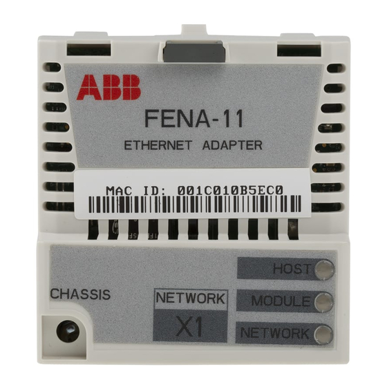
Page 41: Layout Of The Adapter Module
Overview of the Ethernet network and the FENA-01/-11/-21 module Layout of the adapter module This figure shows the layout of FENA-01/-11. Description See chapter Lock Mechanical installation Mounting and grounding Mechanical installation screw Connector X1 to Ethernet Electrical installation Diagnostic LEDs Modbus/TCP –... - Page 42 42 Overview of the Ethernet network and the FENA-01/-11/-21 module This figure shows the layout of FENA-21. Description See chapter Lock Mechanical installation Mounting screw Mechanical installation RJ-45 connector [X1] to Electrical installation Ethernet RJ-45 connector [X2] for Electrical installation...
-
Page 43: Mechanical Installation
See also, the applicable drive hardware manual. Unpacking and examining the delivery 1. Open the option package. 2. Make sure that the package contains: • Ethernet adapter module, type FENA-01/-11/-21 • this manual. 3. Make sure that there are no signs of damage. -
Page 44: Installing The Adapter Module
44 Mechanical installation Installing the adapter module WARNING! Obey the safety instructions. See chapter Safety instructions on page 19. If you ignore the safety instructions, injury or death can occur. The adapter module has a specific position in the drive. Plastic pins, a lock and one screw to hold the adapter module in place. - Page 45 Mechanical installation 2. Put the adapter module carefully into its position on the drive. 3. Push in the lock. 4. Tighten the screw to torque 0.8 N·m using a Torx TX10 screwdriver. WARNING! Do not use excessive force, or leave the screw too loose.
- Page 46 46 Mechanical installation...
-
Page 47: Electrical Installation
Electrical installation Electrical installation Contents of this chapter This chapter contains: • general cabling instructions • instructions on connecting the adapter module to the Ethernet network. Warnings WARNING! Obey the safety instructions. See chapter Safety instructions on page 19. If you ignore the safety instructions, injury or death can occur. -
Page 48: General Cabling Instructions
STP. When CAT5 FTP or STP is used, the cable shield is connected to the drive frame through an RC network. In FENA-01, it is possible to change this connection by using jumper J1 located next to the X1 connector. -
Page 49: Connection Procedure
Electrical installation Connection procedure 1. Connect the network cable to the RJ-45 connector (X1) on the adapter module. 2. If you want to create a daisy chain with FENA-21 adapter modules, connect the X2 connector of the first adapter module to X1 on the next adapter module, and so on. - Page 50 50 Electrical installation...
-
Page 51: Modbus/Tcp Protocol
Modbus/TCP protocol Modbus/TCP – Start-up ....... Modbus/TCP – Communication profiles . -
Page 53: Modbus/Tcp - Start-Up
Modbus/TCP – Start-up Modbus/TCP – Start-up Contents of this chapter This chapter contains: • information on configuring the drive for operation with the adapter module • drive-specific instructions on starting up the drive with the adapter module • information on configuring the client for communication with the adapter module. -
Page 54: Drive Configuration
54 Modbus/TCP – Start-up Drive configuration The information in this section applies to all drive types compatible with the adapter module, unless otherwise stated. Modbus/TCP connection configuration After the adapter module has been mechanically and electrically installed according to the instructions in chapters Mechanical installation Electrical... -
Page 55: Fena-01/-11-/21 Configuration Parameters - Group A
2 = MB/TCP T16 Modbus/TCP: Transparent 16-bit profile 3 = MB/TCP T32 Modbus/TCP: Transparent 32-bit profile 4 = MB/UDP ABB C Modbus over UDP: ABB Drives profile - Classic 5 = MB/UDP ABB E Modbus over UDP: ABB Drives profile - Enhanced... - Page 56 56 Modbus/TCP – Start-up Name/Value Description Default IP configuration Sets the method for configuring the IP address, 1 = Dyn subnet mask and gateway address for the IP DHCP module. 0 = Static IP Configuration will be obtained from parameters 05…13.
- Page 57 Modbus/TCP – Start-up Name/Value Description Default Subnet CIDR Subnet masks are used for splitting networks into smaller networks called subnets. A subnet mask is a 32-bit binary number that splits the IP address into a network address and host address. Subnet masks are typically represented in either dotted decimal notation or the more compact CIDR notation, as shown in the table...
- Page 58 58 Modbus/TCP – Start-up Name/Value Description Default Commrate port 2 Sets the bit rate for the Ethernet port 2. 0 = Auto This parameter is used only with FENA-21. 0 = Auto Auto-negotiate 1 = 100 Mbps FD 100 Mbps, full duplex 2 = 100 Mbps HD 100 Mbps, half duplex 3 = 10 Mbps FD...
- Page 59 Modbus/TCP – Start-up Name/Value Description Default Timeout time Defines the Modbus/TCP timeout value. The Modbus protocol does not specify a timeout mechanism for the application layer. A timeout mechanism may be desired when controlling a drive, so the adapter module provides a method for this purpose.
- Page 60 60 Modbus/TCP – Start-up Name/Value Description Default 1 = HiLo The first register contains the high order word and the second register contains the low order word. Address mode Defines the mapping between parameters and holding registers in the 0...65535 Modbus Mode 0 register range.
- Page 61 Modbus/TCP – Start-up Name/Value Description Default Reserved for web These parameters are not used by the adapter … page functionality. module when the module is configured for For more Modbus/TCP. information, see Appendix C – FENA configuration pages. FBA A/B par Validates any changed adapter module 0 = Done refresh...
- Page 62 62 Modbus/TCP – Start-up Name/Value Description Default D2FBA A/B comm Read-only. Displays the status of the fieldbus 0 = Idle status adapter module communication. Note: The value names may vary by drive. 4 = Off- line 2 = Time 0 = Idle Adapter is not configured.
- Page 63 Modbus/TCP – Start-up Name/Value Description Default FBA A/B appl SW Read-only. Displays firmware version of the adapter module in xxyy format, where: xx = major revision number yy = minor revision number Example: 310 = 3.10 Version number is the form: <major>.<minor>.<patch>.<build>...
-
Page 64: Fena-01/-11/-21 Configuration Parameters - Group B
64 Modbus/TCP – Start-up FENA-01/-11/-21 configuration parameters – group B (group 2) Note: The actual parameter group number depends on the drive type. Group B (group 2) corresponds to: • parameter group 55 in ACS355 • parameter group 53 in ACSM1, ACS380, ACS480, ACS580, ACS850 and ACQ810. -
Page 65: Fena-01/-11/-21 Configuration Parameters - Group C
Modbus/TCP – Start-up FENA-01/-11/-21 configuration parameters – group C (group 3) Note: The actual parameter group number depends on the drive type. Group C (group 3) corresponds to: • parameter group 54 in ACS355 • parameter group 52 in ACSM1, ACS480, ACS580, ACS850 and ACQ810 •... -
Page 66: Control Locations
ABB drives can receive control information from multiple sources including digital inputs, analog inputs, the drive control panel and a fieldbus adapter module. ABB drives allow the user to separately determine the source for each type of control information (Start, Stop, Direction, Reference, Fault reset, etc.). -
Page 67: Starting Up Fieldbus Communication For Acs355 Drives
1…2 and actual values 1…2 automatically to Modbus registers. Process data groups are not available for the ABB Drives - Classic communication profile. 7. Validate the settings made in parameter groups 51, 54 and 55 with parameter 5127 FBA PAR REFRESH. -
Page 68: Parameter Setting Examples - Acs355
Speed and torque control using the ABB Drives – Enhanced communication profile This example shows how to configure a speed and torque control application that uses the ABB Drives - Enhanced profile. In addition, some application-specific data is added to the communication. - Page 69 Setting for ACS355 Description drives 5102 FB PAR 2 1 (= MB/TCP ABB E) Selects the Modbus/TCP (PROTOCOL/PROFILE) protocol and the ABB Drives - Enhanced profile. 5103 FB PAR 3 0 (= Auto) Ethernet communication rate is (COMMRATE) negotiated automatically by the device.
- Page 70 70 Modbus/TCP – Start-up Drive parameter Setting for ACS355 Description drives 9904 MOTOR CTRL 2 = VECTOR: TORQ Selects the vector control mode MODE as the motor control mode. 1001 EXT1 COMMANDS 10 = COMM Selects the fieldbus interface as the source of the start and stop commands for external control location 1.
-
Page 71: Starting Up Fieldbus Communication For Acsm1 Drives
Modbus/TCP – Start-up Starting up fieldbus communication for ACSM1 drives 1. Power up the drive. 2. Enable the communication between the adapter module and the drive with parameter 50.01 FBA ENABLE. 3. With parameter 50.02 COMM LOSS FUNC, select how the drive reacts to a fieldbus communication break. -
Page 72: Parameter Setting Examples - Acsm1
Speed and torque control using the ABB Drives – Enhanced communication profile This example shows how to configure a speed and torque control application that uses the ABB Drives - Enhanced profile. In addition, some application-specific data is added to the communication. -
Page 73: Drives
Displays the type of the fieldbus adapter module. 51.02 FBA PAR2 1 (= MB/TCP ABB E) Selects the Modbus/TCP (PROTOCOL/PROFILE) protocol and the ABB Drives - Enhanced profile. 51.03 FBA PAR3 0 (= Auto) Ethernet communication rate is (COMMRATE) negotiated automatically by the device. - Page 74 74 Modbus/TCP – Start-up Drive parameter Setting for ACSM1 Description drives 51.05 FBA PAR5 First part of the IP address (IP ADDRESS 1) 51.06 FBA PAR6 Second part of the IP address (IP ADDRESS 2) 51.07 FBA PAR7 Third part of the IP address (IP ADDRESS 3) 51.08 FBA PAR8 Last part of the IP address...
- Page 75 Modbus/TCP – Start-up Drive parameter Setting for ACSM1 Description drives 32.02 TORQ REF ADD FBA REF2 Selects the fieldbus reference 2 as the source for torque reference 1. 34.01 EXT1/EXT2 SEL P.FBA MAIN CW.15 Enables external control location 1/2 selection through the fieldbus only (bit 15 in the fieldbus Control word).
- Page 76 76 Modbus/TCP – Start-up Starting up fieldbus communication for ACS850 and ACQ810 drives 1. Power up the drive. 2. Enable the communication between the adapter module and the drive with parameter 50.01 FBA enable. 3. With parameter 50.02 Comm loss func, select how the drive reacts to a fieldbus communication break.
-
Page 77: Parameter Setting Examples - Acs850 And Acq810
This example shows how to configure a speed control application that uses the ABB Drives - Enhanced profile. In addition, some application-specific data is added to the communication. The start/stop commands and reference are according to the ABB Drives profile. - Page 78 Displays the type of the fieldbus adapter module. 51.02 FBA par2 1 (= MB/TCP ABB E) Selects the Modbus/TCP protocol (PROTOCOL/ and the ABB Drives - Enhanced PROFILE) profile. 51.03 FBA par3 0 (= Auto) Ethernet communication rate is (COMMRATE) negotiated automatically by the device.
- Page 79 Modbus/TCP – Start-up Drive parameter Setting for Description ACS850/ACQ810 drives 51.05 FBA par5 First part of the IP address (IP ADDRESS 1) 51.06 FBA par6 Second part of the IP address (IP ADDRESS 2) 51.07 FBA par7 Third part of the IP address (IP ADDRESS 3) 51.08 FBA par8 Last part of the IP address...
-
Page 80: Starting Up Fieldbus Communication For Acs480, Acs580 And Acs880 Drives
80 Modbus/TCP – Start-up The start sequence for the parameter example above is given below. Control word: • Reset the fieldbus communication fault (if active). • Enter 47Eh (1150 decimal) → READY TO SWITCH ON. • Enter 47Fh (1151 decimal) → OPERATING (Speed mode). Starting up fieldbus communication for ACS480, ACS580 and ACS880 drives 1. - Page 81 1…2 and actual values 1…2 automatically to Modbus registers. Process data groups are not available in the ABB Drives - Classic communication profile. 8. Save the valid parameter values to permanent memory with parameter 96.07 Parameter save manually.
-
Page 82: Parameter Setting Examples - Acs480 And Acs580 Drives
Frequency control using the ABB Drives – Enhanced communication profile This example shows how to configure a frequency control application that uses the ABB Drives - Enhanced profile. In addition, some application-specific data is added to the communication. The start/stop commands and reference are according to the ABB Drives profile. - Page 83 Displays the type of the fieldbus adapter module. 51.02 Protocol/Profile 1 = MB/TCP ABB E Selects the Modbus/TCP protocol and the ABB Drives - Enhanced profile. 51.03 Commrate 0 = Auto Ethernet communication rate is negotiated automatically by the device.
- Page 84 84 Modbus/TCP – Start-up Drive parameter Setting for ACS480 Description and ACS580 drives 22.11 Speed ref1 4 = FB A ref1 Selects the fieldbus A reference 1 as source the source for speed reference 1. 31.11 Fault reset 06.1.7 Selects the fieldbus interface as selection the source for the fault reset signal.
-
Page 85: Parameter Setting Examples - Acs880
This example shows how to configure a speed control application that uses the ABB Drives - Enhanced profile. In addition, some application-specific data is added to the communication. The start/stop commands and reference are according to the ABB Drives profile. - Page 86 128 = ETHERNET Displays the type of the fieldbus adapter module. 51.02 Protocol/Profile 1 = MB/TCP ABB E Selects the Modbus/TCP protocol and the ABB Drives - Enhanced profile. 51.03 Commrate 0 = Auto Ethernet communication rate is negotiated automatically by the device.
- Page 87 Modbus/TCP – Start-up Drive parameter Setting for ACS880 Description drives 22.11 Speed ref1 source 4 = FB A ref1 Selects the fieldbus A reference 1 as the source for speed reference 31.11 Fault reset 30 = FBA A MCW bit 7 Selects the fieldbus interface as selection the source for the fault reset...
-
Page 88: Client Configuration
88 Modbus/TCP – Start-up Client configuration After the adapter module has been initialized by the drive, you must prepare the client for communication with the module. Due to the large number of different Modbus clients, specific instructions cannot be provided here. Refer to the documentation of your client for more information. -
Page 89: Modbus/Tcp - Communication Profiles
Modbus client and the drive. With the FENA adapter module, the Modbus/TCP network may employ either the ABB Drives profile or one of two Transparent modes for 16-bit and 32-bit words respectively. For the ABB Drives profile, data is converted by the adapter module into the native profile (e.g., DCU or FBA). - Page 90 Can be used if the native profile is supported by the drive. The following sections describe the Control word, the Status word, references and actual values for the ABB Drives communication profile. Refer to the drive manuals for details on the native profiles.
-
Page 91: Abb Drives Communication Profile
The drive states are presented on page 95. Control word contents The table below shows the contents of the Control word for the ABB Drives communication profile. The upper case boldface text refers to the states shown in the state machine on page 95. Name... - Page 92 92 Modbus/TCP – Communication profiles Name Value STATE/Description INHIBIT_ Proceed to OPERATION ENABLED. OPERATION Note: Run enable signal must be active; see drive documentation. If the drive is set to receive the Run enable signal from the fieldbus, this bit activates the signal. Inhibit operation.
-
Page 93: Status Word Contents
(Not supported with ACS355) Status word contents The table below shows the contents of the Status word for the ABB Drives communication profile. The upper case boldface text refers to the states shown in the state machine on page 95. - Page 94 94 Modbus/TCP – Communication profiles Name Value STATE/Description ALARM Warning/Alarm No warning/alarm OPERATION. Actual value equals reference SETPOINT (= is within tolerance limits, i.e., in speed control, speed error is 10% max. of nominal motor speed). Actual value differs from reference (= is outside tolerance limits.) REMOTE Drive control location: REMOTE (EXT1 or...
-
Page 95: State Machine
Modbus/TCP – Communication profiles State machine The state machine for the ABB Drives communication profile is shown below. SWITCH-ON ABB Drives MAINS OFF INHIBITED (SW Bit6=1) communication Power ON (CW Bit0=0) profile NOT READY TO SWITCH ON (SW Bit0=0) = Control word... -
Page 96: References
ABB drives can receive control information from multiple sources including analog and digital inputs, the drive control panel and a fieldbus adapter module (for example, FENA). To have the drive controlled through the fieldbus, you must select the module as the source for control information, for example, reference. -
Page 97: Actual Values
Modbus/TCP – Communication profiles Actual values Actual values are 16-bit words containing information on the operation of the drive. The functions to be monitored are selected with a drive parameter. Scaling Actual values are scaled as shown below. Note: The values of REF1 MAX and REF2 MAX are set with drive parameters. - Page 98 98 Modbus/TCP – Communication profiles...
-
Page 99: Modbus/Tcp - Communication Protocol
Modbus messaging over TCP connection on an IP network. The FENA adapter module acts as a Modbus/TCP server with support for the ABB Drives and Transparent profiles. The adapter module also supports Modbus over UDP. The only difference between Modbus/TCP and Modbus/UDP is that in Modbus/UDP the transport layer protocol is UDP instead of TCP. -
Page 100: Register Addressing
100 Modbus/TCP – Communication protocol Further information on the Modbus/TCP protocol is available at www.modbus.org. Register addressing The address field of Modbus Requests for accessing Holding registers is 16 bits. This allows the Modbus protocol to support addressing of 65536 Holding registers. Historically, Modbus client devices used 5-digit decimal addresses from 40001 to 49999 to represent Holding register addresses.