Table of Contents
Advertisement
Quick Links
EN
Instructions
Rexroth NYS04.2-ST-02-LMSN-NY4073
1
About this Documentation
1.1 Overview – target groups & product phases
The target groups, product phases and activi-
ties that can refer to this document are marked
in rounded boxes in the following figure.
Mounting
Product phases
Selection
(assembly/installation)
Presales Aftersales
Design engineer
Mechanic/
electrician
Programmer
Technologist
Process
specialist
Target groups
To select
To unpack
To prepare
To mount
Activities
To design
To install
To construct
1.2 Intended audience
This document explains technical and service
personnel of the machine builder how to safely
install the system housing mechanically and
electrically. This document is not the usage
manual.
1.3 Availability
These Instructions are part of the
NYS04.2-ST-02-LMSN-NY4073 system hous-
ing product delivery and must always be avail-
able for the user.
If the system housing is handed over to another
person, these Instructions must be handed over
as well.
June 13, 2019
Bosch Rexroth AG
Electric Drives and Controls
Bgm.-Dr.-Nebel-Str. 2
D-97816 Lohr am Main
Telefon +49 (0)9352-18-0
Telefax +49 (0)9352-18-8400
www.boschrexroth.com
Engineering
Operation
De-commissioning
Commissioning
Programmer
Commissioning engineer
Technologist
Process specialist
Machine
operator
Maintenance
technician
Mechanic/
electrician
Service
Disposal company
To parameterize
To optimize
To operate
To dismount
To program
To test
To maintain
To dispose
To remove
To configure
faults
To create
To simulate
the program
1.4 Included parts
Type code
NYS04.2-ST-02-LMSN-NY4073
DOK-NY4000-SYST*4073**-IT07-
EN-P
Headers for the 24V System, SE, DP and M
connectors are also included.
1.5 Variations
These Instructions apply to the NYCe 4000
system housings with the following type code:
• NYS04.2-ST-02-LMSN-NY4073
1.6 Further available documentation
The following documentation contains detailed
information. Use the listed documentation or a
newer version, if available.
Title and type code
Rexroth NYCe 4000
Hardware System Manual
DOK-NY4000-HW***SYSTEM-PRRS-EN-E
Rexroth NYCe 4000
Standard Housings & Accessories Manual
DOK-NY4000-HOUSING*ACC-PRRS-EN-E
1.7 Additional parts
Motion Control Units, host adapter, drive
modules, connection cables, and more are
listed in the project planning manuals or on
www.boschrexroth.com
2
Product Identification and Scope of
Delivery
2.1 Product identification
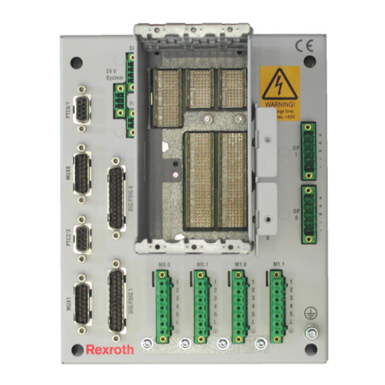
The NYS04.2-ST-02-LMSN-NY4073 has one
slot for the MCU and two slots for drive mod-
ules.
Page 1 of 13
Material
Description
number
R911172908
System housing
R911339004
Instructions
Material number
R911337671
R911337672
R911339004-07_BAL_DOC
Advertisement
Table of Contents

Related Manuals for Bosch Rexroth NYS04.2-ST-02-LMSN-NY4073


Summary of Contents for Bosch Rexroth NYS04.2-ST-02-LMSN-NY4073
- Page 1 1.4 Included parts Bosch Rexroth AG Electric Drives and Controls Type code Material Description Bgm.-Dr.-Nebel-Str. 2 number D-97816 Lohr am Main NYS04.2-ST-02-LMSN-NY4073 R911172908 System housing Telefon +49 (0)9352-18-0 Telefax +49 (0)9352-18-8400 DOK-NY4000-SYST*4073**-IT07- R911339004 Instructions www.boschrexroth.com EN-P Headers for the 24V System, SE, DP and M connectors are also included.
- Page 2 TYP: NYS04.2-ST-02-LMSN-NY4073 MNR: R911172908 POWER INPUT IP20 I-C-B-H-T-V FD: 15W12 View of the NYS04.2-ST-02-LMSN-NY4073 Power Marking label on the right side of the module holder See the following table for an explanation of The discharge warning label the fields indicated by a number. warns the technician to observe a 5 minute discharge time delay Logotype...
-
Page 3: Ambient Conditions
Using the Safety Instructions lowed in explicitly indicated combinations of parts. 3.1 Safety instructions - structure Do not install and use this system housing The safety instructions are structured as shown before you have read all relevant documents. in the following example. You must read the safety instructions and all other directions for use before you start any work or activity with this system housing. -
Page 4: Technical Data
8.2 CE marking through the ventilation holes. In particular, bend cables away from the ventilation holes as Declaration of Conformity near to the connectors as possible. The system housing described in the present instructions, comply with the requirements and Technical Data the target of the following EU directive and Requirements on Mains Circuits. - Page 5 8.3 UL certification Interfaces 9.1 Overview Designation Connection type Connection Connection on base plate (base plate) (cable) 24V System 24V DC system 3-pin male Phoenix Contact power supply MC 1,5/ 3-STF-3,5 Service inputs 4-pin male Phoenix Contact MC 1,5/ 4-STF-3,5 System fan unit 2-pin male The system housing...
- Page 6 9.6 DP – Drive power supply Connector data minimum maximum MC 1,5/ 3-STF-3,5 Drive power supply for drive modules Tightening torque 1,95 lbs*inch (0,22 Nm) 2,21 lbs*inch (0,25 Nm) NYM04.1-2PW-NNNN-NY4120/10. Wire diameter 30 AWG (0,14 mm 14 AWG (1,5 mm __________________________________ Voltage on the pins of this connector can be higher than 60V DC.
- Page 7 9.7 M – Motor connections A fuse must be installed between the pow- er supply output voltage and the drive power ______________________________________ input voltage connection. The rating of the fuse Voltage on the pins of depends on the used cables and application re- this connector can be higher than 60V DC.
-
Page 8: Installation And Removal
9.10 Dig/Fdig – 24V power supply for Digital I/O These measures are also recommended for the and Fast Digital I/O connections other digital I/O. The 24V SELV power supply for the digital I/O and fast digital I/O connections are on the connectors ‘DIG/FDIGx’... - Page 9 ≥ 100 mm (forced cooling) ≥ 200 mm (convection cooling) ≥ 100 mm (forced cooling) ≥ 200 mm (convection cooling) Dimensions (front view) of the NYS04.2-ST-02-LMSN-NY4073 The minimum distance above and below the system housing is required for cooling. Bend all cables connected below the module holder away from the ventilation holes as near to the connectors as possible.
- Page 10 First connect the 24V power supply plug. Then connect the drive power supply plug. 10.3 Protective Earth connection For safety reasons, the protective earth connec- tion via the threaded earth post is mandatory. The protective earth connection must be connected before any other cables are connect- ed to the system housing.
-
Page 11: Maintenance
In all system housings the slot on the left- - Check that cables are not damaged. most side is called ‘MCU’ and is a slot dedi- cated for the installation of the Motion Control Unit (MCU). 12 Description of the System Housing The adjacent slots at the right side of the The system housing has no indicators. - Page 12 Our products can be returned to us free of Our service department at our main facility charge for disposal. It is a precondition, how- Bosch Rexroth AG ever, that the products are free of oil, grease or Bgm.-Dr.-Nebel-Str. 2 other dirt. In addition, when returned the prod-...
- Page 13 Notes R911339004-07_BAL_DOC June 13, 2019 Page 13 of 13...