Table of Contents
Advertisement
Quick Links
Advertisement
Table of Contents

Related Manuals for Bosch rexroth CS610


Summary of Contents for Bosch rexroth CS610
- Page 1 CS610 Anti-Ice Controller User Manual...
-
Page 2: Table Of Contents
LOGGING REPORT ..........................15 Bosch Rexroth Canada Corp. reserves the right to revise this information at any time and for any reason and reserves the right to make changes at any time, without notice or obligation, to any of the information contained in this piece of literature. -
Page 3: Layout
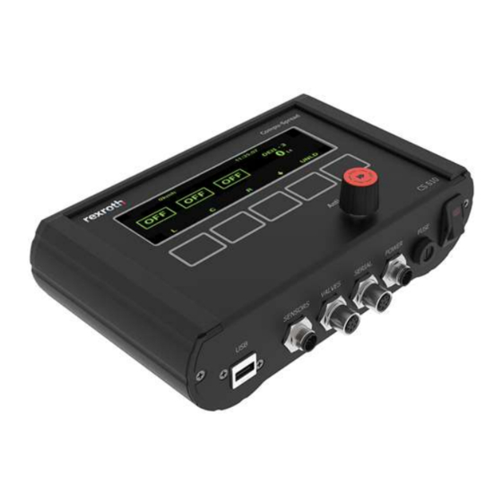
LAYOUT CS 610 is anti-icing programmable controller, which can operate in manual, closed or open loop mode, for the controlled application of liquids used in snow and ice control. Encoder with push button Touch Pads Power Switch Fuse Power Cable Serial Cable USB Port Sensor Cable... -
Page 4: Main Menus
MAIN MENUS When truck is stopped or no ground speed signal comes in, the screen will look like as below if configured for 3 boom mode (standard):... -
Page 5: Authorization Verification
AUTHORIZATION VERIFICATION To set up the CS-610, either a security USB or a password is needed according to the setting of feature LOCK, this is to prevent unauthorized personnel from making adjustments to the system. Once press the ‘SETUP’, it goes to the screen to require a security USB key or the input of the password. If it is password verification, the screen will look like that: Version number Please Enter Code... - Page 6 Press to switch between region and truck name. Press CHG to start to edit region or truck name, Then press FINSH button to quit editing. Setting the UNIT UNIT: To choose the system unit, metric or imperial. Authorization method LOCK: A valid programing key or six characters password can be chosen to verify the access to the setup. Setting the Time TIME: Clock time is formatted as: Hour: Minute: Second Setting the Date...
-
Page 7: Ground Speed Calibration
PAR: reset parameters to factor defaults A text page will come out to confirm the action. GROUND SPEED CALIBRATION There are two ways to do the speed calibration. If the resolution is known, just manually input the pulses per KM or Mile. The other way is to set up the predetermined speed as the speed that truck will run more often. -
Page 8: Hydraulic Valve Configuration
HYDRAULIC VALVE CONFIGURATION The left side of screen is to set up the valves configuration. RECIR: 90% Mode There are eight anti-ice modes. Only closed loop modes can be “Auto nulled”. --- Manual Mode This mode allows the driver to manually control the application rate. Each setting on the Conveyor Dial is a percentage of maximum null setting. - Page 9 This mode utilizes the ground speed sensor only to regulate the amount of material that will be dispensed off the vehicle. There are 9 configurable application rate settings available. The display will show “O” on the screen. This is just for a single output. This mode will allow the operator selection of any combination of three outputs. --- 3 boom closed loop This mode utilizes both the flow meter and ground speed sensors to regulate the amount of material that will be dispensed off the vehicle.
-
Page 10: Material Calibration
Material Name Press ENTER to choose different liquid material. RECIR: 90% FINISH Use up/down arrow to view each material’s settings and press FINSH to select the material. If CHG is pressed, system will start to edit the material name which is consist of 4 characters. After finish editing the material name then press DONE. -
Page 11: Data Saving/Loading/Displaying
RECIR: 90% Turn knob to run ABORT FINISH After press FINSH, it will go to the page to input the material weight to calculate the WT/REV and the result will be displayed on the screen. Measure material Enter Number Vol: 000.0 ABORT FINISH DATA SAVING/LOADING/DISPLAYING... - Page 12 Display the trip and season totals When truck is stopped, Press TOTAL to display trip and season totals. Total distance material actually applied Season totals are reset in Setup menu Total distance travelled Total liquid dispensed Data logging Reset Trip total screen (on next only page)
-
Page 13: Sub Menus
Use up/down arrow to navigate and press SELCT to load the desired parameter file. Load REGION_REX01? Once confirmed all the parameters will be refreshed in the memory. To save the loaded parameters, it needs to enter the setup screen and exit normally. 8.5 Save logging data to USB When truck is stopped, Press TOTAL first, then press DATA, insert log key and follow the hints on screen. -
Page 14: Error Messages
Make sure that the vehicle is stationary (ground speed = 0) Press UP and DOWN buttons to adjust simulated ground speed. Under the simulation mode, the system still counts the spreading information into log, so please clear that by resetting screen totals and retrieving logging data with USB. Material change Press the down arrow, then press once more to enter the sub, sub menu. -
Page 15: Spreading Screen
Turn the dials until the desired speed is achieved. Press QUIT to exit unload mode. Moving the vehicle will suspend the unload process. It will automatically resume when the truck is stopped again. SPREADING SCREEN When truck is moving, system will display spreading screen. 40kmh STAT Press STAT will go to the diagnosis screen which displays the power voltage, actual flow meter frequency and... -
Page 16: Update Firmware
UPDATE FIRMWARE Copy the latest bin file to the root directory of USB Program Key and rename it to Rexroth2.bin, plug it into the USB port and then power on the controller, it will upgrade firmware automatically. Unplug the USB stick once “Verified”... - Page 17 15.2 Select Report All the logging data will be displayed in the data zone. It is also possible to select the logging data involving multiple trucks under a region. When selecting data, if option All Data is selected and no specific truck is selected, then all the trucks in that region will be used.
- Page 18 15.3 View Report The logging reports will be displayed on the sheet called “Report” by clicking on ‘Display Truck’ after choosing the criteria at the above section. For example, here you can select region “Toroto” and truck “TUCK03”. • Click Display Truck will go to Report Sheet...
- Page 19 15.4 Delete Truck Truck data or region can be cleaned by clicking “delete Truck”. Warning message will pop out to confirm the operation.