
Related Manuals for Electrolux Frytop 1200


Summary of Contents for Electrolux Frytop 1200
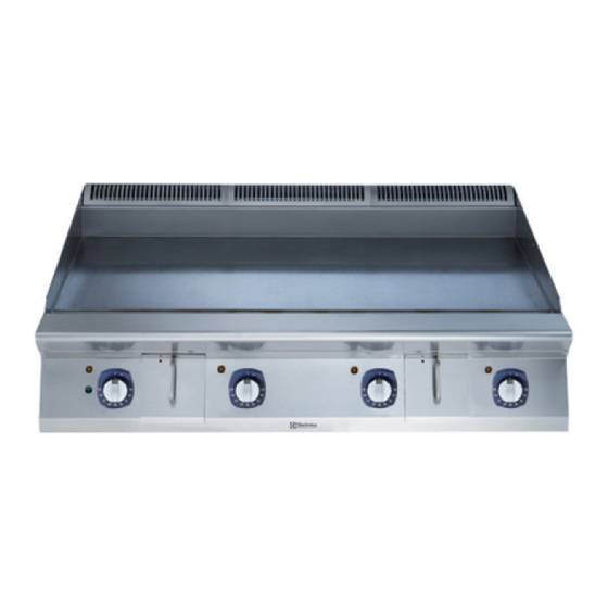
- Page 1 Frytop 1200 EFT93 Installation and operating manual * 59589G900- 2019.07 *Original instructions...
- Page 2 Foreword The installation, use and maintenance manual (hereinafter Manual) provides the user with information necessary for correct and safe use of the machine (or “appliance“). The following must not be considered a long and exacting list of warnings, but rather a set of instructions suitable for improving machine performance in every respect and, above all, preventing injury to persons and animals and damage to property due to im- proper operating procedures.
-
Page 3: Table Of Contents
Contents A SAFETY INFORMATION ......................... 5 General information ........................5 Personal protection equipment ......................5 General safety ..........................6 General safety rules ........................7 Safety signs to be placed near the machine area ................. 8 Transport, handling and storage ...................... 9 Installation and assembly ....................... - Page 4 G MACHINE CLEANING AND MAINTENANCE..................... 20 Ordinary maintenance ......................... 20 G.1.1 informations for maintenance....................20 G.1.2 Cleaning the appliance and accessories ................20 G.1.3 External parts........................20 G.1.4 Other surfaces........................21 G.1.5 Periods of non-use ......................21 Brief Troubleshooting guide (gas models) ..................21 Repair and extraordinary maintenance ....................
-
Page 5: Asafety Information
SAFETY INFORMATION General information To ensure safe use of the machine and a proper understanding of the manual it is necessary to be familiar with the terms and typographical conventions used in the documentation. The following symbols are used in the manual to indicate and identify the various types of hazards: WARNING Danger for the health and safety of operators. -
Page 6: General Safety
Summary table of the Personal Protection Equipment (PPE) to be used during the various stages of the machine's service life. (cont'd.) Stage Protective Safety Gloves Glasses Safety garments footwear helmet — ● ○ — — Unpacking — ● ○ — —... -
Page 7: General Safety Rules
• Do not use products (even if diluted) containing chlorine (sodium hypochlorite, hydrochloric or muriatic acid, etc.) to clean the appliance or the floor under it. • Do not use metal tools to clean steel parts (wire brushes or Scotch Brite type scouring pads). -
Page 8: Safety Signs To Be Placed Near The Machine Area
– clean and dry; – well lit. For the Customer's complete information, the residual risks remaining on the machine are indicated below: such situations are deemed improper and therefore strictly forbidden. Residual risk Description of hazardous situation Slipping or falling The operator can slip due to water or dirt on the floor Burns/abrasions (e.g. -
Page 9: Transport, Handling And Storage
Danger Meaning caution, hot surface danger of electrocution (shown on electrical parts with indication of voltage) End of use • When the appliance is no longer to be used, make it unusable by removing the mains power supply wiring. Transport, handling and storage •... -
Page 10: Machine Space Limits
• Verify that a safety circuit breaker is installed between the power cable of the appliance and the mains electric line. The contact opening max. distance and leakage current must comply with the local safety regulations. • Be sure to power the equipment with systems that are protected against overvoltage; the manufacturer declines all responsibility for effects due to anomalies induced by the electrical supply system. -
Page 11: Machine Cleaning And Maintenance
risks for the safety of operators and damage to the appliance are not allowed. Reasonably foreseeable improper use includes: • lack of machine maintenance, cleaning and periodical checks; • structural changes or modifications to the operating logic; • tampering with the guards or safety devices; •... -
Page 12: Machine Disposal
Repair and extraordinary maintenance • Repair and extraordinary Maintenance have to be carried out by specialised authorised personnel. The manufacturer declines any liability for any failure or damage caused by the intervention of an unauthorised technician by the Manufacturer and the original manufacturer warranty will be invalidated. -
Page 13: Btechnical Data
EN 203–1 EU standard logo IMQ/GS gas category gas pressure Pmbar Electrolux Professional SpA Viale Treviso 15 33170 Porde- manufacturer none Italy Dataplate position IMPORTANT This instruction manual contains information relevant to various appliances. See the dataplate located under the control panel to identify the appliance (see image below). -
Page 14: Gas Appliance
Children shall not play with the appliance. Cleaning and user Manufacturer Electrolux Professional SpA or any other maintenance shall not be made by children without supervision. service centre authorised by Electrolux Professional SpA. -
Page 15: Responsibility
Safety device a device (other than a guard) that elimi- • unauthorized modifications or operations; nates or reduces the risk; it can be used • missing, lack or inadequate maintenance; alone or in combination with a guard. • improper machine use; Customer the person who purchased the machine •... -
Page 16: Joining Appliances
Gas, electricity, water and other Polyethylene connections (if present, depending on the • Outer wrapping appliance and/or model) • Instructions bag • Any installation work or maintenance to the supply system (gas, electricity, water and/or steam, if present) must only Polypropylene be carried out by the utility company or an authorised installation technician. -
Page 17: Gas Pressure Regulator
Countertop models (Only for N9E range) 2. correct adjustment of primary air supply to burner/s 3. pilot nozzle/s replacement 1. See the installation diagram for the position of the gas connection on the bottom of the appliance. 4. minimum flame screw/s replacement 2. -
Page 18: Pilot Burner Nozzle Replacement
2. Unscrew nozzle “C“ (see Frytop burner — Fig. 2) and 8. Prior to operation, test the gas pressure regulator for leaks. replace it with one suitable for the type of gas, according to that given in table “B“ (see Appendix); The nozzle diameter is given in hundredths of mm on the nozzle body. -
Page 19: E.10.3 Power Cable
E.10.3 Power cable The contact opening max. distance and leakage current must comply with the local safety regulations. Unless otherwise specified, our appliances are not equipped with a power cable. E.11 Safety thermostat The installer must use a flexible cable having characteristics Appliances equipped with safety thermostat (overheating not lower than the H07RN-F rubber insulated type. -
Page 20: Switching Off
Electrical models 2. Press down fully and turn it to position A click will indicate sparking. The electric fry top consists of four cooking zones (from left to right) controlled by four thermostats, one for each zone. 3. Keeping knob “A“ pressed, turn it to position. -
Page 21: Other Surfaces
NOTE! G.1.4 Other surfaces Replace the blade of the scraper whenever it is not Chrome plated surfaces (daily) perfectly sharp. 1. Do not use chlorine-based products, as they can damage the hot-plate; Tanks and collection drawers (even several times a day) 2. -
Page 22: Repair And Extraordinary Maintenance
Gas valve 1. Remove the knobs and control panel; 2. Unscrew the pilot and thermocouple pipe; 3. Unscrew the gas inlet and outlet connections; 4. Lift the cooking plate at the front and remove the thermostat bulb; 5. For installation carry out the same procedure in reverse order. Pilot burner, thermocouple, igniter 1. -
Page 23: Maintenance Contacts (Only For Australia)
For service and spare parts, please contact: • Diamond - Semak Food Service Equipment — 18, 87– 91 • Electrolux - Tom Stoddart Pty Ltd — 39 Forest Way, Hallam South Road, Hallam VIC 3803 — call 03-9796-4583 Karawatha QLD 4117 — call 1-300-307-289... - Page 26 Electrolux Professional SPA Viale Treviso 15 33170 Pordenone www.electrolux-professional.com...