Table of Contents
Advertisement
Quick Links
Advertisement
Table of Contents

Related Manuals for Kenwood CO-1506


Summary of Contents for Kenwood CO-1506
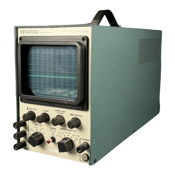
- Page 1 C O - 1 5 0 6 130mm OSCILLOSCOPE MANUAL I N S T R U C T I O N...
-
Page 2: Specifications
F E A T U R E S 20 mV/cm vertical sensitivity and wide frequency • High response M H z . • Considerable reduction of weight and size as compared w i t h conventional 130 m m type allowing perfect portability, oscilloscopes, •... -
Page 3: Circuit Description
F U S E 0 . 3 A 1 5 0 0 V - 15V 4- 1 8 0 V Power fransformer, primary side Fig. 1 B L O C K D I A G R A M O F CO-1506... -
Page 4: Front Panel
PANEL CONTROLS AND T H E I R FUNCTIONS V E R T A T T FRONT PANEL T h i s is the vertical attenuator. It is used to attenuate a signal voltage fed to A C terminal (1) or D C terminal the vertical input terminal coupled to T h i s is V . -
Page 5: Rear Panel
the knob of the switch; the red mark on the shaft REAR PANEL appears. (14) I N T E N S I T Y SWEEP RANGE (Hz) T h i s is the bright line control. It is used to adjust the This is the sweep frequency selector switch and is intensity of light of waveform on C R T . - Page 6 OPERATING INSTRUCTIONS Calculate the voltage according to the equation below. G E N E R A L METHODS OF OPERATION Voltage = Amplitude x sensitivity A waveform to be viewed is fed to V . I N P U T terminals (1) an alternative, the voltage can be obtained by a and G N D (2) or (2) and D C terminal ( 3 ) .
- Page 7 D C voltages are measured as displacements of the bright line through the V . I N P U T DC terminal (13). A DC voltage displayed on the C R T is directly read as its effective value. i : l 2 : l : H) Sensitivity (V/cm) x A cm = Voltage (V)
- Page 8 APPLICATIONS MEASURING AUDIO AMPLIFIER F R E Q U E N C Y RESPONSE Supply a sine wave to the A U X terminal of the audio amplifier from a signal generator and connect the speaker output terminals of the amplifier to V . I N P U T (1) and G N D ( 2 ) .
- Page 9 To the E X T S Y N C / H . I N P U T terminal of CO-1506 generator output level should be set as low as possible. T h e cable from the sweep generator and other leads from Fig.
-
Page 10: Modulation Measurement
Fig. 12 How to measure modulation degree Tuning circuit Volume control variable resistor in the detector circuit T o CO-1506 E X T S Y N C / H . I N P U T Fig. 11 Adjusting AM receiver MODULATION MEASUREMENT Common... -
Page 11: Maintenance And Adjustment
CAUTIONS ON HANDLING T H E SET MAINTENANCE AND ADJUSTMENT 1. Select a place not exposed to direct sunbeam for 3. Aligning the C R T bright line: (a) Loosen the three screws (16) clamping the C R T . T h e installation of this oscilloscope. - Page 12 (b) Place the oscilloscope in the normal operating posi- Other adjustment tion with respect to the poles of the earth. When a 100kHz square wave is applied to the A C terminal (1) and G N D ( 2 ) , the overshoot is corrected by (c) T u r n the C R T by the cover until the bright line is adjusting T C 3 .
-
Page 13: Parts List
PARTS LIST PARTS LIST OF X65-1080-00, 21 D e s c r i p t i o n Part N o . p e l . N o . Part N o . C a s e D e s c r i p t i o n A Q 1 - 0 2 5 8 0 2 R e f . - Page 14 PARTS LIST OF X68-1130-00 Part N o . D e s c r i p t i o n R e f . N o , R N 1 4 A B 3 D 4 7 3 J Metal f i l m 4 7 k £ l ±...
- Page 15 P C BOARD X68-1130-00 X65-1080-00,21...
- Page 16 KENWOOD CORPORATION © 9 6 0 0 6 PRINTED IN JAPAN B50-1289-10(N)