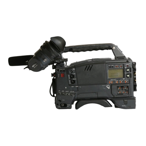
Panasonic AJ-HDC27V Operating Instructions Manual
Vtr
Hide thumbs
Also See for AJ-HDC27V:
- Operating instructions manual (116 pages) ,
- Operating instructions manual (118 pages)
Table of Contents
Advertisement
Quick Links
Advertisement
Table of Contents

Related Manuals for Panasonic AJ-HDC27V


Summary of Contents for Panasonic AJ-HDC27V
- Page 1 Camera/VTR Operating Instructions...
- Page 2 FCC Note: CAUTION This device complies with Part 15 of the FCC Rules. RISK OF ELECTRIC SHOCK To assure continued compliance follow the attached DO NOT OPEN installation instructions and do not make any unauthorized modifications. CAUTION: TO REDUCE THE RISK OF ELECTRIC SHOCK, DO NOT REMOVE COVER (OR BACK).
-
Page 3: Table Of Contents
........53 Using the Panasonic AU-BP402 battery pack . . .22 Setting the synchro scan mode . -
Page 4: Cam Main Menu
Contents Setting menu screens ..... .79 <VTR MENUS> VTR MAIN MENU screen ....96 <CAM MENUS>... -
Page 5: Introduction
Introduction The AJ-HDC27V integrates two units: 1) a high- Furthermore, it is compact and lightweight, has low definition (HD) color video camera featuring an IT- power consumption, and excels in achieving a high CCD equipped with a 1 million pixel on-chip lens that level of picture quality, sensitivity, and mobility, and is supports the full spectrum of HD TV (720P/59.94 Hz),... - Page 6 Features Features of the camera unit Wide-ranging video gain selection 4-piece filter disc sets available as standard A value ranging from –6 dB to +30 dB can be selected accessories for the gain using the setting menu and GAIN switch. The filter best suited to the subject’s brightness and Even when the gain is increased for shooting in dark color temperature can be selected.
-
Page 7: Features Of The Vtr Unit
Features Features of the VTR unit Digital system Built-in DOLBY NR system The pictures are compressed by a component digital The cue audio recording circuitry contains a Dolby B recording system that uses the latest compression noise reduction circuit. technology while non-compression PCM recording Audio functions featuring excellent signal-to-noise ratio, frequency O A phantom power supply type of microphone... -
Page 8: System Configuration
System Configuration Wireless Microphone kit microphone AJ-MC700P receiver WX-RJ700 2˝ viewfinder AJ-HVF27P Microphone holder AJ-MH700P Battery Panasonic Battery Battery case charger AU-BP402 Lens AU-M402H AG-B425 AJ-BP490 (Bayonet type) AJ-B450 FUJINON/CANON Anton/Bauer Battery Battery Sony Battery case/Battery BP-90 holder BP-L60/L90 NP-1... -
Page 9: Parts And Their Functions
Parts and their functions Power supply section Accessory mounting section 1 Hooks for attaching shoulder strap 1 Battery mount Attach the ends of the accessory shoulder strap to these hooks. This is for attaching the Anton/Bauer battery pack. 2 Light shoe 2 DC IN (external power input) socket (XLR, 4P) Use this to attach the video light, etc. -
Page 10: Audio Function Section
Parts and their functions Audio function section (1) 1 MIC IN (microphone input) jack (XLR, 3-pin) 5 AUDIO IN CH1/CH2 (audio input channel 1 & 2) Connect the microphone (optional accessory) here. connectors (XLR, 3-pin) The power for the microphone is supplied from this An audio component or microphones are connected jack. - Page 11 Parts and their functions Audio function section (2) < Speaker = > The EE sound during recording or the playback sound during playback can be monitored through this speaker. The warning alarms are output in synchronization with the flashing or lighting of the warning lamps <...
-
Page 12: Viewfinder Section
Parts and their functions Viewfinder section > < 3 TALLY switch This is used to control the front tally lamp 7. HIGH : The brightness of the front tally lamp is increased. OFF : The front tally lamp is turned off. LOW : The brightness of the front tally lamp is reduced. -
Page 13: Shooting (Recording)/Playback Function Section
Parts and their functions $ Examples of filter selection Shooting (recording)/playback function section (1) Shooting conditions CC filter ND filter Sunrise, sunset, inside a studio B (3200 K) 1 (CLEAR) Outdoors under a clear sky C (4300 K) or 2 (1/4 ND) or D (6300 K) 3 (1/16 ND) Outdoors under cloudy or rainy... - Page 14 Parts and their functions Shooting (recording)/playback function section (2) 5 GAIN (gain selector) switch This is used to select the gain of the video amplifier in accordance with the lighting status during shooting. The gain values corresponding to the L, M and H settings are specified by the setting menu ahead of time.
- Page 15 Parts and their functions Shooting (recording)/playback function section (3) 7 SHUTTER switch 9 HD SDI OUT connector (BNC) This is set to ON when the electronic shutter is to The HD SDI signals (video and audio) for the be used. When the SEL side is pressed, the monitor in accord with the position of the MONITOR OUT SDI switch : are output from here.
- Page 16 Parts and their functions Shooting (recording)/playback function section (4) < : SDI switch < VTR START button This is used to select the video and audio signals When this is pressed, recording starts; when it is which are to be output from the HD SDI OUT pressed again, recording stops.
- Page 17 Parts and their functions Shooting (recording)/playback function section (5) > > MODE CHECK button C PLAY/PAUSE button While this button is held down, the camera’s setting This is pressed to view the playback picture on the mode is shown in the viewfinder. viewfinder screen or using a color video monitor.
-
Page 18: Warning/Status Display Section
Parts and their functions Warning/status display section 1 Back tally lamp (unit) When the back tally switch 2 is set to ON, this lamp serves the same function as the front tally lamp in the viewfinder. 2 Back tally switch This is used to control the unit’s back tally lamp 1. -
Page 19: Menu Operation Section
Parts and their functions Menu operation section 3 JOG dial button When this dial button is turned while the menu screen is displayed, the cursor is moved to each of the setting items. The menu items are set by operating this dial button. - Page 20 Parts and their functions Time code related section (2) 4 HOLD button 7 “+” button, “–” button The time data display of the counter display section These are used to increment or decrement by 1 the which was on the screen at the moment when this figure in the digit which was made to flash by the SHIFT button 8 when the time code or user’s bit is button is pressed is held.
-
Page 21: Power Supply
Attach the battery pack. To use the battery pack, there is a choice of three Insert the pack in the direction shown by the makes of batteries, namely: O Panasonic arrows, and then slide it into position. O Anton/Bauer O Sony Power output socket for lighting <Note>... -
Page 22: Using The Panasonic Au-Bp402 Battery Pack
Power supply Using the Panasonic AU-BP402 battery pack Detach the battery mount. Attach the AU-M402H battery case. Open the battery case cover, and raise it above the rubber cap: screw holes will now be visible. Tighten the screws using a screwdriver, then attach the case to the unit and tighten the screws fully. -
Page 23: Using The Sony Np-1 Battery Pack
Power supply Using the Sony NP-1 battery pack Using the Sony BP-90 battery pack Detach the battery mount. Attach the accessory battery mounting connector. See page 22. Attach the battery case for the BP-90. Attach the accessory battery mounting connector. 1. -
Page 24: Using The Sony Bp-L60/L90 Lithium-Ion Battery
Power supply Using the Sony BP-L60/L90 lithium- Using an AC power supply When the AJ-B75 AC adapter is used ion battery Connect the DC OUT connector on the AJ-B75 AC Attach the accessory battery mounting connector. adapter to the EXT DC IN socket on the unit. (Refer to the previous page.) Attach the battery holder for the lithium-ion battery. -
Page 25: Attaching The Lens
Attaching the lens Raise the lever for securing the lens, and detach Push the cable into the cable clamp, and connect it the mount cap. to the LENS socket. Lever for securing the lens Mount cap LENS socket <Notes> Align the center mark of the lens with the groove in O For details on handling the lens, refer to the the top center of the lens mount, and attach the operating instructions which accompany the lens. -
Page 26: Adjusting The Lens Flange
Adjusting the lens flange If the subject is not focused properly in the telephoto and wide-angle modes during zoom operations, adjust the flange back (distance from the lens mounting surface to the image-forming surface). Once this adjustment is done, it need not be redone unless the lens is replaced. -
Page 27: Adjusting The White Shading
Adjusting the white shading Follow the procedure outlined below when the white 1 Perform the menu operations (pages 72 to 74), shading needs to be re-adjusted. and display the “VF DISPLAY” screen of CAM MAIN MENU 2. Adjustment method 2 Set ZEBRA1 DETECT to 70%, ZEBRA2 DETECT to 85% and ZEBRA2 to STOP. - Page 28 Adjusting the white shading 1 Set the WHITE BAL selector switch to “A” or “B,” If the lens is provided with an extender, engage the extender function, and repeat steps and initiate the automatic white balance (AWB) adjustment using the AUTO W/B BAL switch. 2 Initiate the automatic black balance (ABB) The white shading adjustment is now complete.
-
Page 29: Adjusting The Viewfinder
Adjusting the viewfinder (The viewfinder is an optional accessory.) Attaching the viewfinder Detaching the viewfinder Check that the camera’s POWER switch is at OFF. Check that the camera’s POWER switch is at OFF. Connect the plug to the viewfinder connecting Loosen the stopper screw, pull the viewfinder terminal. -
Page 30: Adjusting The Viewfinder Position
Adjusting the viewfinder (The viewfinder is an optional accessory.) Adjusting the viewfinder position Pull up the lever for securing the viewfinder in the back/front and sideways directions to disengage the lock. Lever Viewfinder Loosen the lever for securing the viewfinder in the back/front and sideways directions. -
Page 31: Audio Input Preparation
Audio input preparation When attaching a microphone to the viewfinder (optional accessory) for use The microphone of the AJ-MC700P mic kit (optional accessory) can be attached to the viewfinder. Open the mic holder. Set the AUDIO IN switch or switches to “FRONT” in accordance with the audio channel or channels AJ-HVF27P whose sound is to be recorded. -
Page 32: When Attaching A Microphone To The Main Unit For Use
Audio input preparation When attaching a microphone to the main unit for use Attaching the AJ-MH700P mic holder (optional accessory) Remove the screws used to attach the mic holder. Connect the microphone’s connecting cable to the MIC IN jack on the camera. MIC IN jack Set the AUDIO IN switch or switches to “FRONT”... -
Page 33: Mic In Jack
Audio input preparation When connecting a microphone to When connecting a microphone to the MIC IN jack the AUDIO IN connector Connect the microphone’s connecting cable to the Connect the microphone’s connecting cable to the MIC IN jack on the camera. AUDIO IN connector on the camera. -
Page 34: When Using A Wireless Microphone
When connecting audio components Attach the WX-RJ700 wireless receiver when Connect the AUDIO IN connectors on the camera Panasonic’s wireless system is to be used. with the audio component using the XLR cable. Attach the WX-RJ700 wireless receiver to the WX- ZJ770 camera attachment. -
Page 35: Mounting The Unit On A Tripod
Mounting the unit on a tripod Use the tripod attachment available as an optional Detaching the unit from the tripod attachment accessory for mounting the unit onto a tripod. While pressing the red lever, move the black lever in the direction of the arrow, slide the unit toward the rear, and detach it. -
Page 36: Attaching The Shoulder Strap
Attaching the shoulder strap Attach the shoulder strap to the shoulder strap To detach the shoulder strap, open the clips on the mounting hooks, and adjust the length of the strap. mounting parts and detach. <Note> Check that the shoulder strap is securely fastened. The clip opens when it Shoulder strap is pressed here. -
Page 37: Attaching The Rain Cover
Attaching the rain cover Example showing use of the SHAN- RC700 rain cover Tighten the cord. Close using the fastener. Close using the fastener. Connecting the extension control unit By connecting the AJ-EC3 extension control unit <Notes> O Before connecting or disconnecting the dedicated (optional accessory), some of the functions can be operated by remote control. -
Page 38: Viewfinder Lamp Displays
Viewfinder lamp displays TALLY / REC BATT Viewfinder pictured here is the AJ-HVF27P SAVE (For details concerning the viewfinder, refer to the operating intructions of the viewfinder.) 1 TALLY/REC (recording) lamp 4 VTR SAVE (VTR power-saving) lamp This lights up (red) during recording. It flashes This lights when the VTR SAVE/STBY switch is set when a problem has occurred. -
Page 39: Setting The Lamp Displays
Viewfinder lamp displays Setting the lamp displays Select the items targeted for the lamp display on Setting item Description of setting the “!LED” screen of the CAM MAIN MENU 2 screen. GAIN (0 dB) Lamp display appears when the gain is (Under the factory settings, the “!LED”... -
Page 40: Viewfinder Screen Status Displays
Viewfinder screen status displays $ Display items and where they are displayed In addition to the pictures shot, the unit’s settings and messages indicating its operating statuses are 1 Extender display displayed on the viewfinder screen. The center 2 Shutter speed/mode display marker and safety zone markers also appear. - Page 41 Viewfinder screen status displays 1 Extender display ; Safety zone markers This appears when the lens extender is being used. These indicate the 80% or 90% (factory setting) range of the surface area of the viewfinder screen. 2 Shutter speed/mode display The display range proportion is set on the VF This indicates the shutter speed or shutter mode DISPLAY screen of the setting menu.
-
Page 42: Selecting The Display Items
Viewfinder screen status displays Selecting the display items The items to be displayed on the viewfinder screen Selecting the display items can each be set to ON or OFF on the “VF INDICATOR” screen of the CAM MENU or on the Perform the menu operations (pages 72 to 74) to “VTR VF INDICATOR”... -
Page 43: Display Modes And Setting Change Messages
Viewfinder screen status displays Display modes and setting change messages The display of messages advising the user of what changes have been made to the settings and what the adjustment results are can be turned off for some or all of the items displayed. Setting change/adjustment result messages and display modes Display mode setting... -
Page 44: Switching The Display Mode
Viewfinder screen status displays Switching the display mode Setting the camera ID The display mode settings are switched on the VF The camera ID is set on the CAMERA ID screen. DISPLAY screen. Up to ten alphanumerics, symbols and spaces can be used. -
Page 45: Screen Displays
Screen displays Remaining battery charge and Displays relating to time codes audio channel level and These displays light for the time code, CTL and actual remaining tape displays time : Drop frame mode SLAVE : External locking of the time code Remaining tape display HOLD : Time code generator in the hold mode (when the The remaining tape time is displayed using 7 segments. -
Page 46: Adjusting The Date And Time
Adjusting the date and time Adjustments and setup using the setting menus Perform the menu operations (pages 72 to 74), Press the MENU button to exit the menu and display the “TIME/DATE” screen. operations. The setting menu is cleared, and the display n <... -
Page 47: Adjusting The White Balance And Black Balance
Adjusting the white balance and black balance Adjusting the white balance A better picture can be achieved by adjusting the Set the switches as shown in the figure. white balance and black balance in the following sequence: AWB (white balance adjustment) 5 ABB (black balance adjustment) 5 AWB. - Page 48 Adjusting the white balance and black balance Adjusting the white balance Erect a white pattern at a place with the same While the adjustment is in progress, the following conditions as the source of light illuminating the message appears on the viewfinder screen (but subject, zoom in, and shoot the white of the pattern only when “2”...
- Page 49 Adjusting the white balance and black balance Adjusting the white balance When the white balance cannot When there is no time to adjust the white automatically be adjusted balance An error message appears on the viewfinder screen Set the WHITE BAL switch to PRST. The white (when “2”...
- Page 50 Adjusting the white balance and black balance Adjusting the white balance When FILTER INH is set to ON When AWB is adjusted, the color temperature and filter number applying at the time are displayed. If the filter is then turned, the color temperature and filter number are displayed.
-
Page 51: Adjusting The Black Balance
Adjusting the white balance and black balance Adjusting the black balance The black balance needs to be adjusted in the While the adjustment is in progress, the following following cases: message appears on the viewfinder screen (but O When the unit is used for the first time only when “2”... -
Page 52: Setting The Electronic Shutter
Setting the electronic shutter Shutter modes Setting the shutter mode and speed Available shutter modes and shutter speeds O The SHUTTER switch is used to set the shutter speed and the shutter speed in the standard mode. Mode Shutter speed Application O The shutter speed in the SYNCHRO SCAN mode can easily be changed using the SYNCHRO (“+”... -
Page 53: Changing The Shutter Speed And Mode Selection Range
Setting the electronic shutter Changing the shutter speed Setting the synchro scan mode and mode selection range Press the SHUTTER switch from ON to SEL and On the SHUTTER SPEED screen of CAM MENU, the set to SYNCHRO SCAN. setting range of the shutter speed can be restricted to the required range and whether or not to use the special operation mode (SYNCHRO SCAN) can be selected. -
Page 54: Variable Frame Rate
Variable frame rate This camera/VTR enables the frame rate (shooting <Notes> speed) to be set from 4 frames/sec. (3.99 Hz) to 60 In this unit, the frame rate is set by changing the frames/sec. (59.94 Hz). storage time of the optical signals sensed by the CCD. Since the 720P/59.94 Hz format is used for recording Depending on the frame rate setting, the following onto the tape or outputting to the HD SDI OUT... -
Page 55: Scan Reverse
Scan reverse The unit makes it possible to correct the images (by reversing their top and bottom and their left and right) when the prime lens is used for shooting. Setting the scan reverse Perform the menu operations (pages 72 to 74), and display the “FRAME MODE”... -
Page 56: Adjusting The Audio Level
Adjusting the audio level When the AUTO SELECT CH1 and CH2 selector switches are set to AUTO, the audio CH1 and CH2 input levels are adjusted automatically. Proceed as follows to adjust the audio channel 1 and 2 levels manually. Manual audio level adjustments Set the AUTO SELECT CH1 and CH2 selector switches to MAN. -
Page 57: Setting The Time Data
Setting the time data When the user’s bit and time code are both to be used, the user’s bit is set first. If the time code is set first, the time code generator will stop while the user’s bit is being set so that the time code setting will be off. -
Page 58: Setting The Time Code
Setting the time data Setting the time code Set the DISPLAY switch to TC. Set the TCG switch to SET. Switch the TC MODE to DF or NDF on the TC/UB screen of VTR MENU. Select DF to run the time code in the drop frame mode or select NDF to run the time code in the non-drop frame mode. -
Page 59: Externally Locking The Time Code
Setting the time data Externally locking the time code The built-in time code generator is now locked to the reference time code. About 10 seconds after locking, the external lock status will be retained even if the connection of the Set the POWER switch to ON. -
Page 60: How To Use The User Data
How to use the user data The contents of the setting menus can be saved in the Loading the user data user area of the camera’s memory, and they can be loaded from this area. Use of this data speeds up the Perform the menu operations (pages 72 to 74), process of reproducing suitable setup statuses. -
Page 61: Setup Card Operations
Setup card operations Use of the setup memory card (optional accessory) How to eject the setup card enables the setting menu contents to be saved. Use Open the cover by raising its bottom edge, and eject of this data speeds up the process of reproducing the setup card. -
Page 62: Formatting The Setup Card
Setup card operations The operations for saving setting data on the setup To proceed with the formatting of the setup card, card and loading the saved data from the card are turn the JOG dial button to move the arrow (cursor) performed on the CAM CARD READ/WRITE screen to YES, and press the JOG dial button. -
Page 63: Saving The Data Settings On The Card
Setup card operations Saving the data settings on the card Perform the menu operations (pages 72 to 74), Give a title to the selected file. and display the “CAM CARD READ/WRITE” screen. Turn the JOG dial button to move the arrow n <... - Page 64 Setup card operations Give a title to the selected file. If one of the following messages appears when the JOG dial Turn the JOG dial button to move the arrow button is pressed, the data cannot be saved. (cursor) to the WRITE item. Error message Remedial action <...
-
Page 65: Loading The Data Saved On The Card
Setup card operations Loading the data saved on the When the JOG dial button is pressed, the following card message appears. < C A M C A R D R E A D / W R I T E > Perform the menu operations (pages 72 to 74), R E A D S E L E C T... -
Page 66: Cassette Tapes
Cassette tapes Loading a cassette tape Checking for tape slack Check that there are no cables around the cassette Gently push in the reel using your finger and turn the holder or top panel, and set the POWER switch to reel in the direction of the arrow. -
Page 67: Recording
Recording This section describes the basic steps for shooting From adjusting the white balance and and recording. black balance to stopping the recording Before actually departing to shoot scenes, carry out inspections to ensure that the system is functioning Turn on the power, and after inserting the cassette, properly. -
Page 68: Shooting
Recording Shooting Tape function buttons Select the filter to match the lighting conditions, During recording, the tape function buttons (EJECT, and set the WHITE BAL switch to “A” or “B” if REW, FF, PLAY/PAUSE and STOP) will not work. the white balance has been stored in the memory ahead of time. -
Page 69: Scene-To-Scene Continuity
Recording Scene-to-scene continuity If the unit is in the rec-pause mode, it is possible to Ensuring scene-to-scene continuity at ensure scene-to-scene continuity with an accuracy of other times 0 up to 1 frame just by pressing the VTR START Proceed as follows either after the tape has been button or lens VTR button. -
Page 70: Playback
Playback (checking what has been recorded) When the PLAY/PAUSE button is pressed, the playback pictures can be monitored in black and white on the viewfinder screen. These playback pictures can be monitored in two other ways. Rec review Color playback When recording is temporarily stopped and the lens When an HD color monitor is connected to the unit’s RET button is pressed, the last two seconds of the... -
Page 71: Other Vtr Functions
Other VTR functions NEWS REC function INTERVAL REC (intermittent recording) function The NEWS REC function is set using NEWS REC MODE on the VTR MENU “FUNCTION” screen. This function makes simple interval shooting controlling START button (intermittent recording) possible. It proves to be acknowledgment time during recording (by up to 2 particularly effective when shooting programs with a seconds), the time taken for the unit to transfer from... -
Page 72: Menu Operations
Menu operations The setting menu operations are performed using the MENU button and JOG dial button. The menu configuration is divided into the camera unit’s setting menus and VTR unit’s setting menus. It is possible to select the engineer menu which enables all the setting menu items to be set or, alternatively, the user menu which consists of individually tailored menus so that only those menus... -
Page 73: Basic Setting Menu Operations
Menu operations Basic setting menu operations Displaying menus User menu: Engineer menu Press the MENU button. Hold down the MENU button for at least 3 The camera unit’s USER menu screen is seconds. displayed. When the JOG dial button is pressed, the next When the MENU button is pressed again, the VTR MAIN menu screen (of the camera unit) is unit’s USER menu screen is displayed. -
Page 74: Displaying Sub-Menus And Deciding On Settings
Menu operations Displaying sub-menus and deciding Turn the JOG dial button to move the cursor to the on settings desired item to be set, and press the JOG dial button. The digit whose value is to be set now flashes. Operations common to the user menu and engineer menu Example:... -
Page 75: Setting Menu Configuration
Setting menu configuration CAM MAIN MENU 1 MASTER PED MASTER DTL } MATRIX TABLE MASTER GAMMA MATRIX MATRIX R-G R GAIN MATRIX R-B G GAIN B GAIN MATRIX G-R R PEDESTAL MATRIX G-B MATRIX B-R G PEDESTAL MATRIX B-G B PEDESTAL COLOR CORRECTION 1 (SAT)/(PHASE) Mg (SAT)/(PHASE) - Page 76 Setting menu configuration CAM MAIN MENU 2 CAM MAIN MENU 3 VF DIAPLSY DISP CONDITION CAM CARD READ/WRITE SELECT DISP MODE READ VF OUT SELECT VF DTL WRITE ZEBRA1 DETECT CARD CONFIG ZEBRA2 DETECT READ USER DATA ZEBRA2 TITLE LOW LIGHT LVL CAM CARD R/W SELECT ID READ/WRITE VF MARKER...
- Page 77 Setting menu configuration CAM MAIN MENU 4 CAM USER MENU SELECT1 LOW SETTING CAM USER MENU SELECT2 VF DISPLAY MID SETTING VF MARKER HIGH SETTING VF INDICATOR ADDITIONAL DTL1 !LED ADDITIONAL DTL2 CAMERA SW MODE SKIN TONE DTL SUPER GAIN KNEE/LEVEL GAMMA CAMERA SETTING...
- Page 78 Setting menu configuration VTR MAIN MENU FUNCTION NEWS REC MODE HUMID OPE BATTERY/TAPE BATTERY SELECT REC START EXT DC IN SELECT PAUSE TIMER RETAKE MODE BATT NEAR END ALARM HD SDI OUT BATT NEAR END CANCEL BATT END ALARM INTERVAL REC MODE BATT REMAIN FULL INTERVAL REC TIME INTERVAL PAUSE TIME...
-
Page 79: Setting Menu Screens
Setting menu screens (CAM MENU) The main menu consists of CAM MAIN MENU (1 to 4) of the camera and the VTR MAIN MENU of the VTR. These screens are index screens which are used to open the sub-menus. The setting menu is operated with the MENU button and JOG dial button. (Refer to pages 72 to 74 for the menu operations.) CAM MAIN MENU 1 screen CAM MAIN MENU 3 screen... -
Page 80: Cam Main Menu
Setting menu screens (CAM MAIN MENU 1) ROP screen MATRIX screen The ROP (Remote Operation Panel) is set on this The camera matrix is set on this screen. screen. Variable Item Remarks range display Variable Item Remarks range display MATRIX TABLE USER For selecting the color adjustment display. -
Page 81: Color Correction 1 Screen
Setting menu screens (CAM MAIN MENU 1) COLOR CORRECTION 1 screen COLOR CORRECTION 2 screen The camera color saturation adjustments and hue The camera color saturation adjustments and hue adjustments are set on this screen. adjustments are set on this screen. Variable Variable Item... -
Page 82: Low Setting Screen
Setting menu screens (CAM MAIN MENU 1) LOW SETTING screen MID SETTING screen The low level gain is set on this screen. The middle level gain is set on this screen. Variable Variable Item Remarks Item Remarks range display range display MASTER GAIN –6dB... -
Page 83: High Setting Screen
Setting menu screens (CAM MAIN MENU 1) HIGH SETTING screen ADDITIONAL DTL 1 screen The special detail features of the camera are set on The high level gain is set on this screen. this screen. Variable Item Remarks range display Variable Item Remarks... -
Page 84: Skin Tone Dtl Screen
Setting menu screens (CAM MAIN MENU 1) SKIN TONE DTL screen KNEE/LEVEL screen The skin tone detail of the camera is set on this The knee settings of the camera are performed on this screen. screen. Variable Variable Item Remarks Item Remarks range... -
Page 85: Gamma Screen
Setting menu screens (CAM MAIN MENU 1) GAMMA screen The gamma settings of the camera are performed on this screen. Variable Item Remarks range display R GAMMA –15 USER Amount by which the R channel gamma is corrected in respect of the master gamma level. -
Page 86: Vf Display Screen
Setting menu screens (CAM MAIN MENU 2) VF DISPLAY screen The information to be displayed inside the viewfinder is set on this screen. Variable Variable Item Remarks Item Remarks range display range display DISP NORMAL USER NORMAL: LOW LIGHT LVL OFF USER For selecting the light level CONDITION... -
Page 87: Vf Indicator Screen
Setting menu screens (CAM MAIN MENU 2) VF INDICATOR screen CAMERA ID screen The information to be displayed inside the viewfinder The camera ID is set on this screen. is set on this screen. Variable Item Remarks range display Variable Item Remarks range... -
Page 88: Shutter Speed Screen
Setting menu screens (CAM MAIN MENU 2) SHUTTER SPEED screen ! LED screen The shutter speed is set on this screen. The display of the lamp which appears inside the viewfinder is set to ON or OFF on this screen. Variable Item Remarks... -
Page 89: Camera Sw Mode Screen
Setting menu screens (CAM MAIN MENU 2) CAMERA SW MODE screen Variable Item Remarks range display The modes of the camera switches are set on this USER2 SW USER For allocating the screen. S.GAIN functions in USER2 SW. S.IRIS Variable Item Remarks S.BLK... -
Page 90: Cam Main Menu
Setting menu screens (CAM MAIN MENU 3) CAM CARD READ/WRITE screen CAM CARD R/W SELECT screen The settings for saving (writing) the menu data on the Variable Item Remarks setup card, loading (reading) the data from the card, range display and configuring the card are performed on this screen. -
Page 91: Genlock/Iris Screen
Setting menu screens (CAM MAIN MENU 3) GENLOCK/IRIS screen LENS ADJ screen The genlock and iris control settings are performed on The lens adjustments are performed on this screen. this screen. Variable Item Remarks range display Variable Item Remarks range display F2.8 ADJ For outputting the voltage... -
Page 92: Cam User Menu Select 1 Screen
Setting menu screens (CAM MAIN MENU 4) CAM USER MENU SELECT 1, 2 and 3 screens The settings for registering the items (the same as the ones on the CAM MAIN MENU 1, 2 and 3 screens) allocated to the SUB menus to the SUB MENU screen are performed on this screen. Registration ON (¢) or OFF (≥) is set at the head of each item. -
Page 93: Black Shading Screen
Setting menu screens (CAM MAIN MENU 4) BLACK SHADING screen FLARE screen The black shading adjustments are performed on this The camera’s flare settings are performed on this screen. screen. Variable Variable Item Remarks Item Remarks range display range display DETECTION For execution of the digital R FLARE... -
Page 94: Initialize Screen
Setting menu screens (CAM MAIN MENU 4) INITIALIZE screen EVALUATION screen The items which are measured for evaluation The camera menu settings are initialized and scene purposes are set on this screen. files are saved on this screen. (S/N, MODULATION, RESOLUTION, SENSITIVITY) Variable Item Remarks... - Page 95 Setting menu screens (CAM MAIN MENU 4) EVALUATION screen O S/N measurement screen O Resolution measurement screen The resolution measurements are performed on The S/N measurements are performed on this screen. this screen. Variable Item Remarks range display Variable Item Remarks range display...
-
Page 96: Vtr Main Menu Screen
Setting menu screens (VTR MENU) VTR MAIN MENU screen SUB menu Remarks display FUNCTION Index for opening the FUNCTION screen. BATTERY/ Index for opening the BATTERY/TAPE TAPE screen. BATTERY Index for opening the BATTERY SETTING SETTING screen. VTR VF Index for opening the VTR VF INDICATOR INDICATOR screen. -
Page 97: Function Screen
Setting menu screens (VTR MAIN MENU) FUNCTION screen The VTR’s functions are set on this screen. Variable Variable Item Remarks Item Remarks range display range display NEWS REC USER For selecting the VTR HD SDI OUT USER For controlling the output MODE START button SIDE SW... -
Page 98: Battery/Tape Screen
Setting menu screens (VTR MAIN MENU) BATTERY/TAPE screen The warning tone which signals the remaining battery charge and remaining tape and which is heard during shooting can be switched off if they prove to be distracting. Variable Variable Item Remarks Item Remarks range... -
Page 99: Battery Setting Screen
Setting menu screens (VTR MAIN MENU) BATTERY SETTING screen The type of battery to be used is selected and its settings are performed on this screen. Variable Item Remarks range display AJ-BP490 MANUAL For setting the AJ-BP490 AUTO and the PACO HP-90A battery. -
Page 100: Vtr Vf Indicator Screen
Setting menu screens (VTR MAIN MENU) VTR VF INDICATOR screen The information to be displayed in the viewfinder is set on this screen. Variable Variable Item Remarks Item Remarks range display range display TAPE (IND) USER For switching the SAVE LED SAVE&TAPE USER For setting the operation... - Page 101 Setting menu screens (VTR MAIN MENU) MIC/AUDIO screen The MIC/AUDIO settings are performed on this screen. Variable Variable Item Remarks Item Remarks range display range display MIC LOWCUT FRONT USER For setting the high-pass REC CH3/CH4 CH1/2 USER For setting the audio REAR filter for the CH2 mic input.
-
Page 102: Tc/Ub Screen
Setting menu screens (VTR MAIN MENU) TC/UB screen The time code and user’s bit settings are performed on this screen. Variable Variable Item Remarks Item Remarks range display range display TC MODE USER For setting the time code TCG SET HOLD USER For selecting the operation to the DF or NDF mode. - Page 103 Setting menu screens (VTR MAIN MENU) TC/UB screen The time code and user’s bit settings are performed on this screen. Variable Variable Item Remarks Item Remarks range display range display P. OFF LCD USER For setting whether the VITC UB MODE USER USER For setting what is to be...
-
Page 104: Time Date Screen
Setting menu screens (VTR MAIN MENU) TIME DATE screen VTR INITIALIZE screen The time/date settings are performed on this screen. The VTR MENU settings are initialized and the user data is saved on this screen. Variable Item Remarks range display Variable Item Remarks... -
Page 105: Vtr User Menu Select
Setting menu screens (VTR USER MENU SELECT) ON (¢) or OFF (≥) is set on this screen to determine which items are to be registered on the USER MENU screen. The maximum number of VTR unit items which can be registered is 14. FUNCTION screen BATTERY/TAPE screen Variable... -
Page 106: Vtr Vf Indicator Screen
Setting menu screens (VTR USER MENU SELECT) ON (¢) or OFF (≥) is set on this screen to determine which items are to be registered on the USER MENU screen. The maximum number of VTR unit items which can be registered is 14. VTR VF INDICATOR screen MIC/AUDIO screen Variable... -
Page 107: Warning System
Warning system When a problem is detected immediately after the power is turned on or during operation, the user is alerted to the trouble by the display window (LCD), WARNING lamp and the lamps inside the viewfinder and also by warning tones heard from the speaker or earphone. - Page 108 Warning system $ HUMID $ TAPE END LCD display The HUMID display lights. LCD display All the segments flash. The display will flash for 80 minutes after TAPE the condensation detection is released. O The lamp lights when condensation has WARNING lamp WARNING lamp The lamp lights (during stop and in the...
-
Page 109: Emergency Eject
Emergency eject If the cassette cannot be ejected by pressing the While pushing in with the screwdriver, turn the EJECT button, use a screwdriver or similar tool to EMERGENCY screw counterclockwise until the press and turn the EMERGENCY screw. This tape is ejected. -
Page 110: Maintenance
Maintenance Condensation Head cleaning The water vapor in the air may form as tiny droplets Use the AJ-CL12LP cleaning cassette if the heads on the head drum when the unit is moved from a cold need to be cleaned. Take care to read the location to a warm location or used in a very humid instructions accompanying the cleaning tape since the place. -
Page 111: Inspections Prior To Shooting
Inspections prior to shooting Preparation for inspection Inspecting the camera unit Perform the following inspections prior to shooting to Set the camera unit’s switches as shown in the figure check that the systems are operating properly. below. It is recommended that the images be checked using VTR SAVE/STBY: STBY a color monitor. -
Page 112: Inspecting The Viewfinder
Inspections prior to shooting Inspecting the viewfinder Adjust the position of the viewfinder. Set both the AUDIO IN CH1 and CH2 switches to FRONT, and set LEVEL METER on the VTR VF INDICATOR screen of VTR MENU to CH1. Check that the color bar signals are displayed on Check when sound is input from the microphone the viewfinder screen, and adjust the BRIGHT, connected to the MIC IN jack on the lens that the... -
Page 113: Inspecting The Aperture And Zoom Functions
Inspections prior to shooting Inspecting the aperture and Inspecting the VTR unit zoom functions Perform all the steps outlined in section “1. Tape travel inspection” through section “4. Earphone and Set the zoom to the motorized zoom mode, and speaker inspection” one after the other. check its operations in this mode. - Page 114 Inspections prior to shooting Inspecting the VTR unit 5. Inspection using external microphones 2. Automatic audio level adjustment Connect external microphones to the AUDIO IN CH1 and CH2 jacks. function inspection Set the AUDIO IN CH1 and CH2 switches to Set the AUDIO SELECT CH1 and CH2 switch to REAR.
-
Page 115: Specifications
Specifications [GENERAL] [CAMERA UNIT] Pickup device: Supply voltage: 2/3˝ on-chip IT-type CCD (1 million pixels) DC 12 V (DC 11 V—DC 17 V) System: Power consumption: RGB 3-CCD system 39 W (maximum) Total number of pixels: 33 W (during SAVE REC mode) 1370 (H) a 744 (V) Number of effective pixels: Ambient operating temperature:... - Page 116 Specifications [VTR UNIT] [Connector Section] VTR Video System Input AUDIO IN CH1/CH2 (XLRa2, 3-pin female) Sampling frequency: LINE/MIC/MIC+48V switching type : 74 MHz LINE : +4 dBu : 37 MHz : –60 dBu Quantizing: MIC+48V: Phantom +48V, –60 dBu 8 bits MIC IN (XLR, 3-pin female) Video compression system: –40 dBu (switchable to –50 dBu using internal switch)
- Page 117 Specifications [VIEWFINDER] [RELATED COMPONENTS & PARTS] (Optional accessory: AJ-HVF27P) Relating to power supply CRT: Battery pack: 2˝ high-resolution monochrome tube AU-BP402, AJ-BP490 Video system: Battery charger: 720P/59.94 Hz AG-B425 (for charging AU-BP402 battery pack) External adjustment controls: AJ-B450 (for charging AJ-BP490 battery pack) Controls: Battery case: BRIGHT, CONTRAST, PEAKING...
- Page 118 DIVISION OF MATSUSHITA ELECTRIC CORPORATION OF AMERICA Executive Office: 3330 Cahuenga Blvd W., Los Angeles, CA 90068 (323) 436-3500 EASTERN ZONE: One Panasonic Way 4E-7, Secaucus, NJ 07094 (201) 348-7621 Southeast Region: 1225 Northbrook Parkway, Ste 1-160, Suwanee, GA 30024 (770) 338-6835 Central Region:...
- Page 119 This file has been downloaded from: www.UsersManualGuide.com User Manual and User Guide for many equipments like mobile phones, photo cameras, monther board, monitors, software, tv, dvd, and othes.. Manual users, user manuals, user guide manual, owners manual, instruction manual, manual owner, manual owner's, manual guide, manual operation, operating manual, user's manual, operating instructions, manual operators, manual operator, manual product, documentation manual, user maintenance, brochure, user reference, pdf manual...