Table of Contents
Advertisement
Quick Links
4-Burner Griddle Grill
Product no. 399-5937-4 (GR2298905-CU-00)
ASSEMBLY & OPERATING INSTRUCTIONS
⚫
This instruction manual contains important information necessary for the
proper assembly and safe use of the appliance.
⚫
Read and follow all warnings and instructions before assembling/using the
appliance.
⚫
Follow all warnings and instructions when using the appliance.
⚫
Failure to follow these instructions and warnings could result in damage to the
product or injury to the user.
⚫
Keep this manual for further reference.
⚫
Patent Pending.
For Outdoor Use Only
Should you encounter any problems,
CALL US FIRST.
Do not return product to the store.
WE CAN HELP.
For assistance, contact customer service on
Mon to Fri, 8:00am – 5:00pm Pacific Standard time
1 of 31
1-855-803-9312
,
20190710-Ver.1.2
Advertisement
Table of Contents

Related Manuals for Cuisinart GR2298905-CU-00


Summary of Contents for Cuisinart GR2298905-CU-00
- Page 1 4-Burner Griddle Grill Product no. 399-5937-4 (GR2298905-CU-00) ASSEMBLY & OPERATING INSTRUCTIONS For Outdoor Use Only ⚫ This instruction manual contains important information necessary for the proper assembly and safe use of the appliance. ⚫ Read and follow all warnings and instructions before assembling/using the appliance.
-
Page 2: Safety Labels
WARNINGS SAFETY LABELS DANGER: Indicates an imminent hazardous situation which, if not avoided, will result in death or serious injury. WARNING: Indicates a potentially hazardous situation which, if not avoided, could result in death or serious injury. CAUTION: Indicates a potentially hazardous situation which, if not avoided, may result in minor or moderate injury. - Page 3 WARNING ⚫ This outdoor cooking gas appliance must be used only outdoors and must not be used in a building, garage or any other enclosed area. ⚫ This outdoor cooking gas appliance is not intended to be installed in or on boats. This appliance is not intended to be installed in or on recreational vehicles.
- Page 4 USE AND INSTALLATION OF LP GAS CYLINDER (PROPANE TANK) BEFORE INSTALLING: The installation must conform with local codes or, in the absence of local codes, with either the National Fuel Gas Code, ANSI Z223.1/NFPA 54, Natural Gas and Propane Installation Code, CSA B149.1, or Propane Storage and Handling Code, B149.2, or the Standard for Recreational Vehicles, ANSI A 119.2/NFPA 1192, and CSA Z240 RV Series, Recreational Vehicle Code, as applicable.
- Page 5 DANGER ⚫ DO NOT connect this grill to an existing #510 POL cylinder valve with left hand threads. The Type 1 valve can be identified with the large external threads on the valve outlet. ⚫ DO NOT connect to a propane cylinder exceeding its capacity. ⚫...
-
Page 6: Installing Gas Cylinder
INSTALLING GAS CYLINDER 1. Check that the cylinder valve is closed by turning the knob clockwise. 2. Place cylinder into tank holder in bottom cabinet. 3. Place cylinder such that the valve opening faces the table on the right side in such a way that the hose is not kinked/damaged. -
Page 7: Connection Procedures
CONNECTION PROCEDURES Make sure the tank valve is closed (turn valve clockwise until tight). Check the tank valve to ensure it has the proper external male threads. Make sure all burner valves are turned OFF. Inspect valve connections, port, and regulator assembly. -
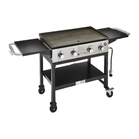
Page 8: Product Diagram
PRODUCT DIAGRAM 8 of 31 20190710-Ver.1.2... -
Page 9: Component List
COMPONENT LIST 1. Hook 2. Side Table Handle 3. Griddle 3pcs 2pcs 4. Side Table 5. Side Table Left Bracket 6. Side Table Right Bracket 2pcs 2pcs 2pcs 7. Griddle Adjustor 8. Grease Drip Tube 9. Left Rear Leg 2pcs 10. - Page 10 13. Right Cart Beam 14. Right Rear Leg 15. Locking Caster 2pcs 16. Tank Holder 17. Tank Hook 18. Right Front Leg 19. Cart Base 20. Front/Rear Cart Beam 21. Tank Holder Supporting Beam 2pcs 10 of 31 20190710-Ver.1.2...
-
Page 11: Hardware List
HARDWARE LIST Item No. Item name Diagram M6x12mm Bolt Symbol: The following symbols will be shown in each procedure to show how the nut and bolt should be tightened. Hand tighten Tighten with tools WARNING ⚫ Please wear gloves while assembling the grill. 11 of 31 20190710-Ver.1.2... - Page 12 Replacement Part List (I) 12 of 31 20190710-Ver.1.2...
- Page 13 Replacement Part List (II) Part Part Name Part Part Name Number Number Hook Side Table Handle Griddle Side Table Side Table Left Bracket Side Table Right Bracket Griddle Adjustor Grease Drip Tube Left Rear Leg Grill Body Assembly Grill Body - Body Grill Body - Carry Over Grill Body - Burner Grill Body - Valve &...
-
Page 14: Assembly Procedures
ASSEMBLY PROCEDURES Step 1 Attach the Right Front & Rear Legs (18 & 14) to the Right Cart Beam (13) and the Tank Holder Supporting Beam (21) using 6 M6x12 Bolts (A). Note: Please note the hole positions on the beams (13 & 21) as shown below. Step 2 Attach the Left Front &... - Page 15 Step 3. Attach the left and right leg assemblies to the Front / Rear Cart Beam (20) using 8 M6x12 Bolts (A). Step 4 Attach the Cart Base (19) to the cart assembly using 12 M6x12 Bolts (A). 15 of 31 20190710-Ver.1.2...
- Page 16 Step 5 Attach the Locking Casters (15) and tighten them to the right legs as shown. Step 6 Fully tighten all the bolts on the cart assembly. 16 of 31 20190710-Ver.1.2...
- Page 17 Step 7 Attach the Tank Holder (16) and the Tank Hook (17) to the cart assembly using 4 M6x12 Bolts (A). Fully tighten the bolts. Step 8 This step needs two people to complete. Attach the Grill Body Assembly (10) to the cart assembly using 4 M6x12 Bolts (A) and fully tighten the bolts. 17 of 31 20190710-Ver.1.2...
- Page 18 Step 9 Attach the Side Table Left & Right Brackets (5 & 6) to the Side Table (4) using 4 M6x12 Bolts (A) as shown below. Attach the Side Table Handle (2) and the Hooks (1) to the Side Table (4) using 2 M6x12 Bolts (A). Tighten all the bolts.
- Page 19 Step 11 Attach the Side Table Left & Right Brackets (5 & 6) and the Side Table Handle (2) to the Side Table (4) using 6 M6x12 Bolts (A). Tighten all the bolts. Step 12 Attach the right side table assembly to the grill body using 4 M6x12 Bolts (A) and tighten all the bolts.
- Page 20 Step 13 Attach the Grease Drip Tube (8) to the grill body using 2 M6x12 Bolts (A) and tighten all the bolts. Step 14 Attach the Griddle Adjustor (7) to the Griddle (3) as shown. Note: Please set up the height of griddle properly before operating the grill. 20 of 31 20190710-Ver.1.2...
- Page 21 Step 15: This step needs two people to complete. Place the griddle on the grill as shown. You can adjust the height of griddle by rotating the griddle adjustor. Warning: Please do not adjust the height of griddle when the grill is hot. Step 16: Your unit is fully assembled! Make sure to read and follow the Instruction Manual before operating this appliance.
-
Page 22: Before Testing
LEAK TEST GENERAL Although all gas connections on the grill are leak tested at the factory prior to shipment, a complete gas tightness check must be performed after assembly to ensure fittings were not damaged after leaving the factory. Periodically check the entire system for leaks following the procedures listed below. -
Page 23: Lighting Instructions
LIGHTING INSTRUCTIONS BEFORE LIGHTING WARNING ⚫ Inspect the gas supply hose prior to turning the gas ON. ⚫ If there is evidence of cuts, wear, or abrasion, the hose must be replaced prior to use. ⚫ Do not use the grill if the odour of gas is present. ⚫... - Page 24 To turn burners off, turn the control knobs clockwise until they lock in the OFF position. USING MATCHES TO LIGHT BURNER Turn OFF all burner valves. Place a long lit match through lighting hole in the left hand side of the grill to approximately 1/2”...
-
Page 25: Flame Characteristics
FLAME CHARACTERISTICS This procedure outlines how to check for proper burner flame characteristics. Burner flames should be blue and stable with little yellow tips, with no excessive noise, or lifting. If the flame is yellow, it indicates insufficient air. If the flame is noisy and tends to lift away from the burner, it indicates too much air. -
Page 26: Burner Cleaning
Spiders and small insects occasionally spin webs or make nests in the grill burner tubes during transit and storage. These webs can lead to gas flow obstruction that could result in a fire in and around burner tubes. This type of fire is known as flashback and can cause serious damage to your grill and create an unsafe operating condition for the user. -
Page 27: Main Burner Replacement
MAIN BURNER REPLACEMENT 1. Remove the griddle. 2. Remove the burner fixing bolt as shown. 3. Remove the carry over. 4. Remove the burner from the grill body. Step 2 Step 4 TO REINSTALL THE MAIN BURNERS: 1. Insert the burner into the burner valve. 2. - Page 28 PROPERLY INSTALL THE BURNER Firmly seat the valve orifice into the burner tube. Make sure the valve orifice is inserted STRAIGHTLY into the burner tube. Burner flames will be yellow, with excessive noise, lifting or flash back if the burner is not installed properly.
-
Page 29: Seasoning The Griddle
SEASONING THE GRIDDLE Seasoning is a process by which oil is baked into metal to create a stick-resistance surface and helps to prevent rusting. It can prolong the life of your griddle. First time use: Wash your griddle with a mild dishwashing detergent to wash off the protective coating applied for shipping. -
Page 30: Troubleshooting
TROUBLESHOOTING Problem: Possible Causes: Corrective Actions: Burner will not 1. LP cylinder fuel is used up. 1. Change a new full LP cylinder. light 2. Electrode tip not in proper 2. Tip of electrode should be pointing position. toward gas port opening on burner. 3. -
Page 31: Limited Warranty
LIMITED WARRANTY The manufacturer warrants this Product to be free from defects in workmanship and materials for a period of one (1) year from the date of purchase, PROVIDED claims are submitted, in writing, with proof of purchase. If any part of this item fails because of a manufacturing defect within the Limited Warranty Period, The manufacturer offers to replace such part(s) provided that such parts have not been improperly repaired, altered, or tampered with or subject to misuse, abuse or exposed to corrosive conditions.