
Related Manuals for GE 6KLP23001X9A1


Summary of Contents for GE 6KLP23001X9A1
- Page 1 GE Consumer & Industrial Electrical Distribution AF-60 LP Micro Drive ™ Installation & Set-up Quick Guide...
- Page 2 Motor overload protection is possible by setting Parameter 1-90 Motor thermal protection to the value Electronic overload trip. For the North American market: Electronic overload functions provide class 20 motor overload protection, in accordance with NEC. Installation in high altitudes: For altitudes above 2 km, please contact GE . DEH-41264A...
-
Page 3: Safety Instructions
Installation on isolated mains source, i.e. IT mains. Max. supply voltage allowed when connected to mains: 440 V. As an option, GE offers line filters for improved harmonics performance. 1.1.6 Avoid unintended Start While the frequency converter is connected to mains, the motor can be started/stopped using digital commands, bus commands, references or via the drive Keypad. -
Page 4: Disposal Instruction
AF-60 LP™ Micro Drive 1.1.7 Disposal Instruction Equipment containing electrical components must not be disposed of together with domestic waste. It must be separately collected with electrical and electronic waste according to local and currently valid legislation. 1.1.8 Before Commencing Repair Work Disconnect AF-60 LP™... -
Page 5: Electrical Installation In General
Non UL compliance: If UL/cUL is not to be complied with, GE recommends using the fuses mentioned in the below table, which will ensure compliance with EN50178/IEC61800-5-1: In case of malfunction, not following the fuse recommendation may result in damage to the frequency converter. - Page 6 AF-60 LP™ Micro Drive Max. fuses UL Ferraz- Ferraz- Max. fuses non UL Bussmann Bussmann Bussmann Littel fuse Shawmut Shawmut 1 X 200-240 V Type RK1 Type J Type T Type RK1 Type CC Type RK1 Type gG 1/4 - 1/2 KTN-R15 JKS-15 JJN-15...
-
Page 7: Connecting To Mains And Motor
AF-60 LP™ Micro Drive 1.1.13 Connecting to Mains and Motor The frequency converter is designed to operate all standard three-phased asynchronous motors. The frequency converter is designed to accept mains/motor cables with a maximum cross-section of 4 mm /10 AWG (M1, M2 and M3) and maximum cross- section 16 mm /6 AWG (M4 and M5). -
Page 8: Control Terminals
AF-60 LP™ Micro Drive 1.1.14 Control Terminals All control cable terminals are located underneath the terminal cover in front of the frequency converter. Remove the terminal cover using a screwdriver. See back of terminal cover for outlines of control terminals and switches. Illustration 1.3: Removing terminal cover. -
Page 9: Power Circuit - Overview
* Brake (BR+ and BR-) are not applicable for Unit Size M1. Brake resistors are available from GE. Improved power factor and EMC performance can be achieved by installing optional GE line filters. GE power filters can also be used for load sharing. -
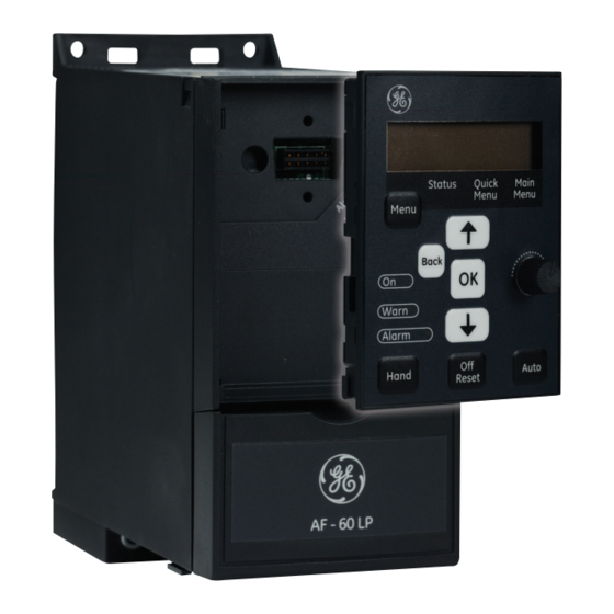
Page 10: Programming With Keypad
The frequency converter can also be programmed from a PC via RS485 com-port by installing the DCT-10 Drive Control Tool. This software can be downloaded from the GE web site: www. geelectrical.com/drives Illustration 1.6: Description of Keypad buttons and display... - Page 11 AF-60 LP™ Micro Drive [Off/Reset]: Stops the motor (off). If in alarm mode the alarm will be reset. [Auto]: The frequency converter is controlled either via control terminals or serial communication. [Potentiometer]: The potentiometer works in two ways depending on the mode in which the frequency converter is running. In Auto Mode the potentiometer acts as an extra programmable analog input.
- Page 12 AF-60 LP™ Micro Drive DEH-41264A...
- Page 13 AF-60 LP™ Micro Drive DEH-41264A...
- Page 14 AF-60 LP™ Micro Drive DEH-41264A...
- Page 15 AF-60 LP™ Micro Drive DEH-41264A...
- Page 16 Err. A wrong password was entered Occurs when using a wrong password for changing a password-pro- tected parameter. These faults may be caused by mains distortions. Installing GE Line Filter may rectify this problem. Table 1.5: Warnings and AlarmsCode list DEH-41264A...
- Page 17 AF-60 LP™ Micro Drive 1.1.18 Mains Supply 1 x 200 - 240 VAC Normal overload 150% for 1 minute Frequency converter Typical Shaft Output [kW] 0.18 0.37 0.75 Typical Shaft Output [HP] 0.25 Unit Size Unit Size M1 Unit Size Unit Size Unit Size IP 20...
- Page 18 AF-60 LP™ Micro Drive 1.1.20 Mains Supply 3 x 380 - 480 VAC Normal overload 150% for 1 minute Frequency converter 0.37 0.75 Typical Shaft Output [kW] Typical Shaft Output [HP] Unit Size Unit Size Unit Size Unit Size Unit Size Unit Size IP 20 Output current...
- Page 19 AF-60 LP™ Micro Drive Protection and Features: • Electronic thermal motor protection against overload. • Temperature monitoring of the heatsink ensures that the frequency converter trips in case of overtemperature • The frequency converter is protected against short-circuits between motor terminals U, V, W. •...
- Page 20 AF-60 LP™ Micro Drive Max. voltage 20 V Current level 0/4 to 20 mA (scaleable) Input resistance, R approx. 200 Ω Max. current 30 mA Analog output: Number of programmable analog outputs Terminal number Current range at analog output 0/4 - 20 mA Max.
- Page 21 AF-60 LP™ Micro Drive Surroundings: Enclosure IP 20 Enclosure kit available IP 21, TYPE 1 Vibration test 1.0 g Max. relative humidity 5% - 95%(IEC 60721-3-3; Class 3K3 (non-condensing) during operation Aggressive environment (IEC 60721-3-3), coated class 3C3 Test method according to IEC 60068-2-43 H2S (10 days) Ambient temperature Max.
-
Page 22: Derating For Ambient Temperature
DIN rail mounting kit for M1 Unit Size NEMA1ACLP4 Type 1 kit for Unit Size M4 NEMA1ACLP5 Type 1 kit for Unit Size M5 DEPLTACLP3 De-coupling plate kit for M4 and M5 frames GE Line Filters and brake resistors are available upon request. DEH-41264A...