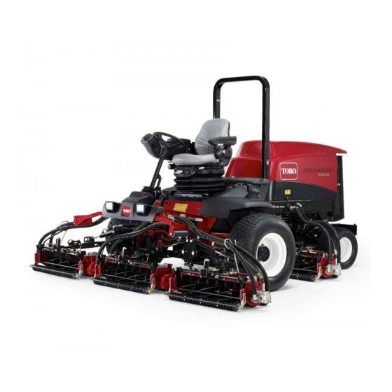
Toro Reelmaster 7000-D Operator's Manual
27 or 32-inch cutting unit traction unit
Hide thumbs
Also See for Reelmaster 7000-D:
- Service manual (468 pages) ,
- Operator's manual (144 pages) ,
- Installation instructions (2 pages)
Table of Contents
Advertisement
Quick Links
Advertisement
Table of Contents

Related Manuals for Toro Reelmaster 7000-D


Summary of Contents for Toro Reelmaster 7000-D
- Page 1 Form No. 3392-124 Rev A 27 or 32-inch Cutting Unit Reelmaster ® 7000-D Traction Unit Model No. 03710—Serial No. 315000001 and Up Model No. 03711—Serial No. 315000001 and Up Model No. 03712—Serial No. 315000001 and Up *3392-124* A Register at www.Toro.com. Original Instructions (EN)
-
Page 2: Table Of Contents
You are responsible for operating the product properly and safely. You may contact Toro directly at www.Toro.com for product Contents safety and operation training materials, accessory information, help finding a dealer, or to register your product. -
Page 3: Safety
Also tighten performance of your Toro equipment, count on Toro any loose nuts, bolts, and screws to ensure cutting unit is genuine parts. When it comes to reliability, Toro delivers in safe operating condition. replacement parts designed to the exact engineering •... -
Page 4: Setup
Setup Loose Parts Use the chart below to verify that all parts have been shipped. Procedure Description Qty. Cutting unit Inspect the cutting unit. Use the kickstand when tipping the – No parts required cutting unit. – No parts required Adjust the rear shield. -
Page 5: Adjusting The Rear Shield
Figure 3 Figure 4 1. Cutting unit kickstand 1. Rear shield 2. Bolt Mounting the Counter Weights Adjusting the Rear Shield No Parts Required No Parts Required Procedure Procedure All cutting units are shipped with the counter weight mounted Under most conditions, the best dispersion is attained when to the left end of the cutting unit. -
Page 6: Adjusting The Cutting Unit Steering
Adjusting the Cutting Unit Steering No Parts Required Increased Steering for the Rear Cutting Units Increase the steering on the rear cutting units by removing the 2 pivot spacers, hex socket screws and flange lock nuts (Figure 8) from the rear (#2 and #3) cutting unit carrier frames (Figure Figure 6... - Page 7 Fixed Steering To lock (fix) the steering on the cutting units, secure the pivot yoke to the carrier frame with the snapper pin (Figure 10). G015977 Figure 10 1. Snapper pin Note: Fixed steering is recommended when cutting side hills.
-
Page 8: Product Overview
Product Overview Specifications Collar Kit (6 per needed per roller): Helps reduce over lap Weight 27 inch, 8 Blade – 77 kg (170 lb) marks for warm season grasses (Bermuda, Zoysia, Paspalum). 27 inch, 11 Blade – 79 kg (175 lb) This kit is installed on the existing Wiehle roller, but is not as aggressive as the Shoulder roller. -
Page 9: Operation
25 mm (1 inch) in from the end of the bedknife on the right hand side of the cutting unit. • Shim 0.0508 mm (0.002 inch)—Toro part number Putting an identifying mark on this blade will make 125-5611 subsequent adjustments easier. Insert the 0.05 mm •... - Page 10 2. Roller bracket 10. Test the cutting performance by inserting a long strip of cutting performance paper (Toro part number 2. Raise rear of cutting unit and place a block under 125-5610) between reel and bedknife, perpendicular bedknife.
-
Page 11: Height-Of-Cut Chart Terms
Height-of-Cut Chart Terms Rear Spacers The number of rear spacers determines the aggressiveness Height of Cut Setting (HOC) of cut for the cutting unit. For a given height of cut, adding spacers, below the side plate mounting flange, increases the The desired Height of Cut aggressiveness of the cutting unit. - Page 12 Chain Links The location at which the lift arm chain is attached determines the rear roller pitch angle (Figure 18). Figure 18 1. Lift chain 3. Bottom hole 2. U Bracket...
-
Page 13: Groomer
Groomer The following chart shows the recommended height of cut settings when a groomer kit is installed on the cutting unit. Height of Cut Chart HOC Setting Aggressiveness of Cut No. of Rear Spacers No. of Chain Links With Groomer kits installed 0.64 cm (0.250 inches) Less... - Page 14 4.13 cm (1.625 inches) * Less Normal More 4.44 cm (1.750 inches) * Less Normal More 4.76 cm (1.875 inches) * Less Normal More 5.08 cm (2.000 inches) * Less Normal More 5.40 cm (2.125 inches) * Less Normal More 5.71 cm (2.250 inches) * Less Normal...
- Page 15 Adjusting the Height of Cut 1. Loosen locknuts securing height-of-cut arms to cutting unit side plates (Figure 19). Figure 21 Figure 19 8-blade cutting unit shown Important: When set properly, the rear and front rollers will contact the gauge bar and the screw 1.
- Page 16 3. If excessive contact/reel drag is evident it will be either necessary to backlap, reface the front of the bedknife, or regrind the cutting unit to achieve the sharp edges needed for precision cutting (Refer to the Toro Manual for Sharpening Reel and Rotary Mowers, Form No. 09168SL).
-
Page 17: Servicing The Bedknife
Servicing The Bedknife The bedknife service limits are listed in the following charts. Important: Operating the cutting unit with the bedknife below the service limit may result in poor after-cut appearance and reduce the structural integrity of the bedknife for impacts. Bedknife Service Limit Chart Bedknife Part No. -
Page 18: Maintenance
Maintenance 2. Using a rag or thickly padded glove, hold on to the reel blade and try to move the reel assembly side to side (Figure 28). Lubrication Each cutting unit has 6 grease fittings (Figure 26) that must be lubricated regularly with No. -
Page 19: Servicing The Bedbar
Servicing the Bedbar Removing the Bedbar 1. Turn bedbar adjuster screws, counterclockwise, to back bedknife away from reel (Figure 30). Figure 32 1. Bedbar bolt 3. Steel washer 2. Nut 4. Nylon washer Assembling the Bedbar 1. Install the bedbar, positioning the mounting ears Figure 30 between the washer and bedbar adjuster. -
Page 20: Servicing The Hd Dual Point Adjusters (Dpa)
Servicing the HD Dual Point 4. Install a wave washer onto the adjuster shaft and slide the adjuster shaft into the flange bushings in the cutting Adjusters (DPA) unit frame (Figure 34). 1. Remove all parts (refer to Installation Instructions for HD 5. -
Page 21: Servicing The Roller
35) are available for the roller rebuild kit. Refer to your parts catalog or contact servicing the roller. The Roller Rebuild Kit includes all the your Authorized Toro Distributor for assistance. Figure 35 1. Rebuild kit (Part No. 114–5430) 6. Bearing nut 2. - Page 22 The method of transmission shall be electronic transmittal. This machinery shall not be put into service until incorporated into approved Toro models as indicated on the associated Declaration of Conformity and in accordance with all instructions, whereby it can be declared in conformity with all relevant Directives.
- Page 23 The Way Toro Uses Information Toro may use your personal information to process warranty claims, to contact you in the event of a product recall and for any other purpose which we tell you about. Toro may share your information with Toro's affiliates, dealers or other business partners in connection with any of these activities. We will not sell your personal information to any other company.
- Page 24 Countries Other than the United States or Canada Customers who have purchased Toro products exported from the United States or Canada should contact their Toro Distributor (Dealer) to obtain guarantee policies for your country, province, or state. If for any reason you are dissatisfied with your Distributor's service or have difficulty obtaining guarantee information, contact the Toro importer.