
Related Manuals for Toro MB TX 2500


Summary of Contents for Toro MB TX 2500
- Page 1 Operator’s Manual MB TX 2500 Tracked Mud Buggy Model—Serial Range 68138—406660000 and Up 68138G—405600000 and Up 68138HD—407100000 and Up *3451-705* A 3451-705A Original Instructions (EN)
-
Page 2: Table Of Contents
Because in some areas there are local, state, or federal regulations requiring that a spark arrester be used on the engine of this machine, a spark arrester is available as an option. If you require a spark arrester, contact your Authorized Service Dealer. Genuine Toro spark arresters are approved by the USDA Forestry Service. -
Page 3: Disclaimers And Regulatory Information
Throttle Control ..........................3–3 Specifications ............................ 3–3 Attachments/Accessories....................... 3–3 Chapter 4: Operation ........................... 4–1 Before Operation ..........................4–1 Before Operation Safety ......................4–1 Fuel ..............................4–2 Performing Daily Maintenance ....................4–3 During Operation ..........................4–3 During Operation Safety ......................4–3 Starting the Engine........................ - Page 4 Hydraulic Lift System......................... 5–26 Checking the Hydraulic Lines ....................5–29 Cleaning............................5–30 Removing Debris ........................5–30 Chapter 6: Storage..........................6–1 Storage Safety ..........................6–1 Preparing the Machine for Storage Over 30 Days..............6–1 Chapter 7: Troubleshooting ....................... 7–1 California Proposition 65 Warning Information Disclaimers and Regulatory Information: Page 4 3451-705A...
-
Page 5: Chapter 1: Introduction
Whenever you need service, genuine Toro parts, or additional information, contact an Authorized Service Dealer or Toro Customer Service and have the model and serial numbers of your product ready. These numbers are located on the serial plate on your product . -
Page 6: Manual Conventions
Manual Conventions This manual identifies potential hazards and has safety messages identified by the safety- alert symbol, which signals a hazard that may cause serious injury or death if you do not follow the recommended precautions. g000502 This manual uses 2 words to highlight information. Important calls attention to special mechanical information and Note emphasizes general information worthy of special attention. -
Page 7: Chapter 2: Safety
Chapter 2 Safety General Safety • Read and understand the contents of this Operator’s Manual before starting the engine. • Do not operate the machine without all guards and other safety protective devices in place and functioning properly on the machine. •... - Page 8 Decal Part: 116-8775 Read the Operator’s Manual. Warning—fill to the bottom of the filler neck; do not overfill the tank. decal116-8775 Decal Part: 125-4967 Lift point decal125-4967 Decal Part: 132-8961 Battery charging condition Hour meter Hopper is raising. Hopper is lowering. Hopper is down.
- Page 9 Decal Part: 132-9051 Tie-down point decal132-9051 Decal Part: 132-9052 Power Auxiliary Logic decal132-9052 Decal Part: 133-8062 decal133-8062 Decal Part: 137-0575 Read the Operator’s Manual. Transmission fluid Cold fill line decal137-0575 3451-705A Page 2–3 Safety: Safety and Instructional Decals...
- Page 10 Decal Part: 137-8899 Read the Operator’s Manual. decal137-8899 Decal Part: 139-7219 decal139-7219 Asphyxiation hazard, poisonous fumes, or toxic Parking brake—disengage gases—do not run the engine in an enclosed Parking brake—engate space. Warning—read the Operator’s Manual; wear Explosion hazard—shut off the engine; do not hearing protection.
- Page 11 Warning—keep bystanders away; look behind and Raise the hopper. down when moving in reverse. Lower the hopper. Warning—engage the parking brake, shut off the Right traction controls engine, and remove the key before leaving the operators position. Engine-speed control Move the handles in to operate. Left traction controls 3451-705A Page 2–5...
-
Page 12: Chapter 3: Product Overview
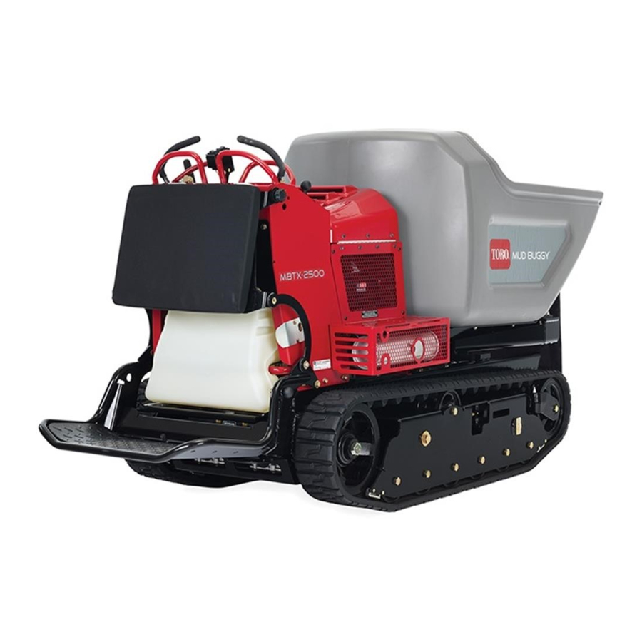
Chapter 3 Product Overview Hopper Hood Control panel Fuel-tank cap Operator platform Tracks g038268 Controls Choke Control the choke before starting a NGAGE cold engine. the choke when the ISENGAGE engine is warm. G376191 Product Overview Page 3–1 3451-705A... -
Page 13: Drive Controls
Drive Controls G375673 Dump Controls Dump hopper Lower hopper G375674 Key Switch Stop engine Run engine Start engine G375755 3451-705A Page 3–2 Product Overview: Controls... -
Page 14: Parking Brake
Discharge height 38.1 cm (15 inches) Attachments/Accessories A selection of Toro approved attachments and accessories is available for use with the machine to enhance and expand its capabilities. Contact your Authorized Service Dealer or authorized Toro distributor or go to www.Toro.com... -
Page 15: Chapter 4: Operation
Chapter 4 Operation Before Operation Before Operation Safety General Safety • Never allow children or untrained people to operate the machine. Local regulations may restrict the age of the operator. The owner is responsible for training all operators and mechanics. •... -
Page 16: Fuel
Before Operation Safety (continued) • If you spill fuel, do not attempt to start the engine; avoid creating any source of ignition until the fuel vapors have dissipated. • Do not fill containers inside a vehicle or on a truck or trailer bed with a plastic liner. Always place containers on the ground, away from your vehicle before filling. -
Page 17: Performing Daily Maintenance
Fuel (continued) Filling the Fuel Tank 1. Clean the area around the fuel-tank cap. 2. Remove the cap. 3. Add fuel until it is at the bottom of the filler neck. Note: Do not fill the fuel tank completely full. The empty space in the tank allows the fuel to expand. - Page 18 During Operation Safety (continued) • Never jerk the controls; use a steady motion. • Use care when approaching blind corners, shrubs, trees, or other objects that may obscure your vision. • Slow down and use caution when making turns and crossing roads and sidewalks with the machine.
-
Page 19: Starting The Engine
During Operation Safety (continued) • Operate up and down slopes with the heavy end of the machine uphill. Weight distribution changes with a full hopper. A full hopper makes the front of the machine the heavy end, so walk behind the machine with the full hopper uphill. •... -
Page 20: Shutting Off The Engine
Starting the Engine (continued) 5. When the engine starts , disengage the choke IMPORTANT Do not engage the starter for more than 5 seconds at a time. If the engine fails to start, allow a 15-second cool-down period between attempts. Failure to follow these instructions can burn out the starter. - Page 21 Operator Platform (continued) • When loading or unloading the machine from a trailer for transport • Driving up slopes Operate the machine with the platform down for the following conditions: • Using the machine in most areas • Driving across slopes •...
-
Page 22: Operating The Hopper
Operator Platform (continued) Raising the Platform 1. Pull out the latch pin and raise the platform. 2. Release the latch pin to lock the platform in place. G384423 Operating the Hopper Hopper capacity: 1134 kg (2,500 lb) Do not exceed the load capacity of the machine. This machine normally operates on uneven, unpaved, bumpy, and/or inclined surfaces—adjust the load accordingly. -
Page 23: Removing Debris From The Machine
After Operation Safety (continued) • Do not touch parts that may be hot from operation. Allow them to cool before attempting to maintain, adjust, or service the machine. • Clean debris from drives, mufflers, and the engine to help prevent fires. Clean up oil or fuel spills. -
Page 24: Raising The Hopper Without Power
Lowering the Hopper without Power (continued) 4. Remove the access panel. G384893 5. Disconnect the hose fittings in the manifold block and allow the fluid to drain into the pan. Note: Dispose of the used fluid at a certified recycling center. 6. -
Page 25: Haul The Machine
Raising the Hopper without Power (continued) 4. Remove the access panel. G384893 5. Disconnect the hose fittings in the manifold block and allow the fluid to drain into the pan. Note: Dispose of the used fluid at a certified recycling center. 6. - Page 26 Haul the Machine (continued) Selecting a Trailer WARNING Loading a machine onto a trailer or truck increases the possibility of tip-over and could cause serious injury or death. • Use only full-width ramps. • Ensure that the length of ramp is at least 4 times as long as the height of the trailer or truck bed to the ground.
- Page 27 Haul the Machine (continued) 3. Lower the ramp(s). 4. Load the machine onto the trailer with the heavy end up the ramp, carrying loads low. • If the machine has a full hopper, drive the machine forward up the ramp •...
-
Page 28: Chapter 5: Maintenance
• Use the cylinder lock to secure the hopper in the raised position. • Never tamper with safety devices. • To ensure safe, optimal performance of the machine, use only genuine Toro replacement parts. Replacement parts made by other manufacturers could be dangerous, and such use could void the product warranty. -
Page 29: Recommended Maintenance Schedule
• Safely relieve all pressure in the hydraulic system before performing any work on the hydraulic system. Recommended Maintenance Schedule Maintenance Qty Description Maintenance Procedure Part No. Service Interval Check the engine oil level., page 5–8 Clean the blower housing., page 5–10 Check the tracks., page 5–16 Check the parking brake... -
Page 30: Pre-Maintenance Procedures
Maintenance Procedure Part No. Service Interval Replace the drive belt., page 5– 139-1295 Belt Change the hydraulic fluid for the Toro premium transmission/ 108-1184 drive system., page 5–25 hydraulic fluid Change the hydraulic fluid for the Toro hypr-oil 500 114-4714 lift system., page 5–28... -
Page 31: Lifting The Machine
Lifting the Machine Ensure that the hopper is empty before lifting the machine. 1. Place the platform in the raised position. 2. Hoist the machine using the 2 lift points under the hopper and the 2 rear tie-down points . Tilt the hopper forward to locate the 2 lift loops and attach a chain or straps at each of the loops. -
Page 32: Using The Cylinder Lock
Using the Cylinder Lock Installing the Cylinder Lock 1. Park the machine on a level surface, move the motion-control levers to the N EUTRAL LOCK position, engage the parking brake, and fully raise the hopper. 2. Remove the 2 cotterless pins securing the cylinder lock to the machine. -
Page 33: Lubrication
Using the Cylinder Lock (continued) 1. Start the machine. 2. Fully raise the hopper. 3. Shut off the engine. 4. Remove the cotterless pins securing the cylinder lock. 5. Place the cylinder lock on the posts inside the machine frame and secure with the cotterless pins. -
Page 34: Engine Maintenance
Engine Maintenance Servicing the Air Cleaner IMPORTANT Do not operate the engine without the air-cleaner element. Operating without an element causes damage to the engine. 1. Rotate the latches outward. 2. Remove the cover to access the air-cleaner elements. 3. Remove the cover to access the air-cleaner elements. -
Page 35: Engine Oil Service
Engine Oil Service Engine Oil Specifications Crankcase capacity: 1.9 L (64 fl oz) Oil type: API classification SJ or later. Oil viscosity: Selected the oil viscosity according to ambient temperature in the table below. g017552 Checking the Engine-Oil Level G376333 1. - Page 36 Engine Oil Service (continued) 3. Open the cowl. 4. Check the engine-oil level. Changing the Engine Oil and Filter 1. Park the machine on a level surface, move the motion-control levers to the N EUTRAL LOCK position, engage the parking brake, raise the hopper, and install the cylinder lock.
-
Page 37: Replacing The Spark Plug
Replacing the Spark Plug 1. Remove the spark-plug wire. 2. Clean around spark plug and remove plug from cylinder head. Note: Replace a cracked, fouled, or dirty spark plug. Do not sand blast, scrape, or clean electrodes because engine damaged could result from grit entering the cylinder. 3. -
Page 38: Fuel System Maintenance
Fuel System Maintenance Replacing the Fuel Filter G376153 1. Park the machine on a level surface, move the motion-control levers to the N EUTRAL LOCK position, engage the parking brake, and lower the hopper. 2. Shut off the engine, and remove the key. Allow the engine to cool. 3. -
Page 39: Removing The Fuel Tank
Removing the Fuel Tank 1. Lower the platform. 2. Release the cushion. 3. Remove the cross bracket 4. Remove the fuel tank and set it on the operator platform. Note: Remove the fuel and vent lines from the top of the tank to move the fuel tank further from the machine. - Page 40 Battery Service (continued) Charging the Battery WARNING Charging the battery produces gasses that can explode. Never smoke near the battery and keep sparks and flames away from battery. IMPORTANT Always keep the battery fully charged (1.265 specific gravity). This is especially important to prevent battery damage when the temperature is below 0°C (32°F).
-
Page 41: Replacing A Fuse
Battery Service (continued) 4. Charge the battery for 1 hour at 25 to 30 A or 6 hours at 4 to 6 A. IMPORTANT Do not overcharge the battery. Positive battery post Negative battery post Red (+) charger lead Black (-) charger lead g003792 5. -
Page 42: Drive System Maintenance
Replacing a Fuse (continued) Main power fuse (15 A) Auxiliary power fuse (15 A) Logic fuse (7.5 A) G376375 1. Release the cushion from the rear of the machine. 2. Pull out the fuse to remove or replace it. 3. Install the cushion to the rear of the machine. Note: Ensure that the correct-size fuse is installed. - Page 43 Track Service (continued) 4. Using a water hose or pressure washer, remove dirt from each track system. IMPORTANT Ensure that you use high-pressure water to wash only the track area. Do not use a high-pressure washer to clean the rest of the machine. Do not use high-pressure water between the drive sprocket and the machine or you may damage the motor seals.
- Page 44 Track Service (continued) 2. Shut off the engine, and remove the key. Allow the engine to cool. 3. Clean the tracks with high-pressure water. IMPORTANT Ensure that you use high-pressure water to wash only the track area. Do not use a high-pressure washer to clean the rest of the machine.
- Page 45 Track Service (continued) 4. Remove the retaining bolt for the tensioning screw. Front wheel Track Tensioning screw and retaining bolt Road wheel Drive sprocket g186008 5. Release the drive tension by turning the tensioning screw clockwise. 6. Remove the track at the top of the front wheel, peeling it off the wheel while rotating the track forward.
-
Page 46: Drive Belt
Drive Belt Inspecting the Drive Belt 1. Park the machine on a level surface, move the motion-control levers to the N EUTRAL LOCK position, engage the parking brake, and lower the hopper. 2. Shut off the engine, and remove the key. Allow the engine to cool. 3. - Page 47 Drive Belt (continued) 7. Remove the 2 bolts and 2 nuts and loosen the 2 set screws on the coupler. Remove the gear pump from the pump mount. Note: You do not need to remove the fittings from the pump. Bolt (2) Pump mount Gear pump...
-
Page 48: Controls Maintenance
Controls Maintenance Adjusting the Motion-Control Levers If the motion-control levers do not align horizontally, adjust the right side motion-control lever. 1. Park the machine on a level surface, lower the hopper, engage the parking brake, shut off the engine, and remove the key. 2. -
Page 49: Brake Maintenance
Brake Maintenance Checking the Parking Brake 1. Park the machine on a level surface, lower the hopper, and engage the parking brake. 2. Start the engine and move the throttle lever to the F position. 3. Move the motion-control levers forward. The machine should not move forward. -
Page 50: Hydraulic System Maintenance
• Toro PX Extended Life Hydraulic Fluid (refer to your Authorized Service Dealer for more information) • If either of the above Toro fluids are not available, you may use another Universal Tractor Hydraulic Fluid (UTHF), but they must be only conventional, petroleum- based products. - Page 51 Hydraulic Drive System (continued) Checking the Hydraulic-Fluid Level for the Drive System 1. Park the machine on a level surface, move the motion-control levers to the N EUTRAL LOCK position, engage the parking brake, and lower the hopper. 2. Shut off the engine, and remove the key. Allow the engine to cool.
- Page 52 Hydraulic Drive System (continued) Changing the Hydraulic Fluid and Filter for the Drive System 1. Park the machine on a level surface, move the motion-control levers to the N EUTRAL LOCK position, engage the parking brake, and lower the hopper. 2.
-
Page 53: Hydraulic Lift System
Mobil® 424 Hydraulic Fluid Hydraulic fluid capacity: 1.4 L (1.5 US gallons) Use only 1 of the following fluids in the hydraulic system: • Toro Premium Transmission/Hydraulic Tractor Fluid (refer to your Authorized Service Dealer for more information) 3451-705A Page 5–26... - Page 54 • Toro PX Extended Life Hydraulic Fluid (refer to your Authorized Service Dealer for more information) • If either of the above Toro fluids are not available, you may use another Universal Tractor Hydraulic Fluid (UTHF), but they must be only conventional, petroleum- based products.
- Page 55 Hydraulic Lift System (continued) 5. Fill the tank with hydraulic fluid only up to the cold level. 6. Install the fill cap. Wipe up any spilled fluid. 7. Remove the cylinder lock and lower the hopper. Changing the Hydraulic Fluid for the Lift System 1.
-
Page 56: Checking The Hydraulic Lines
Hydraulic Lift System (continued) 1. Park the machine on a level surface, move the motion-control levers to the N EUTRAL LOCK position, engage the parking brake, raise the hopper, and install the cylinder lock. 2. Shut off the engine, and remove the key. Allow the engine to cool. -
Page 57: Cleaning
Cleaning Removing Debris IMPORTANT Operating the engine with blocked screens, dirty or plugged cooling fins, and/or cooling shrouds removed, will result in engine damage from overheating. 1. Park the machine on a level surface and shut off the engine. Allow the engine to cool. 2. -
Page 58: Chapter 6: Storage
Chapter 6 Storage Storage Safety • Shut off the engine, remove the key (if applicable), wait for all moving parts to stop, and allow the machine to cool before storing it. • Do not store the machine or fuel near flames. Preparing the Machine for Storage Over 30 Days 1. - Page 59 7. Prepare the fuel system. A. Add a petroleum-based fuel stabilizer/conditioner to the fuel in the tank. Do not use an alcohol-based stabilizer (ethanol or methanol). B. Run the engine to distribute conditioned fuel through the fuel system for 5 minutes. C.
-
Page 60: Chapter 7: Troubleshooting
Chapter 7 Troubleshooting The engine loses power. Possible Cause Corrective Action The engine load is excessive. Reduce the ground speed. The air cleaner is dirty. Service the air-cleaner element. The oil level in the crankcase is low. Add oil to the crankcase. The cooling fins and air passages under the Remove the obstruction from the cooling engine blower housing are plugged. - Page 61 The engine overheats. Possible Cause Corrective Action The engine load is excessive. Reduce the ground speed. The oil level in the crankcase is low. Add oil to the crankcase. The cooling fins and air passages under the Remove the obstruction from the cooling engine blower housing are plugged.
-
Page 62: California Proposition 65 Warning Information
Toro has chosen to provide consumers with as much information as possible so that they can make informed decisions about the products they buy and use. Toro provides warnings in certain cases based on its knowledge of the presence of one or more listed chemicals without evaluating the level of exposure, as not all the listed chemicals provide exposure limit requirements. - Page 63 Notes:...