Advertisement
Quick Links
Safety Control Unit
Thank you very much for purchasing Panasonic products. Read this Instruction Man-
ual carefully and thoroughly for the correct and optimum use of this product. Kindly
keep this manual in a convenient place for quick reference.
● This is an abridged instruction manual simply explains mounting, wiring and etc.
For detailed handling instructions, refer to "SF-C21 Instruction Manual" avail-
able for download at the following.
● Instruction Manuals in the following languages are published on our Web site.
Japanese, English, Chinese, French, Spanish, Italian
• Le manuel d'instructions français est publié sur notre site web.
• El Manual de Instrucciones en español se encuentra publicado en nuestro sitio web.
• Il manuale di istruzioni italiano è pubblicato sul nostro sito web.
1
SAFETY PRECAUTIONS
● Use this device as per its specifications. Do not modify this device since its func-
tions and capabilities may not be maintained and it may malfunction.
● This device has been developed / produced for industrial use only.
● Use of this device under the following conditions or environments is not presup-
posed. Please consult us if there is no other choice but to use this device in such
an environment.
1) Operating this device under conditions or environments not described in this
manual.
2) Using this device in the following fields: nuclear power control, railroad, aircraft,
auto mobiles, combustion facilities, medical systems, aerospace development, etc.
● In case of installing this device to a particular machine, follow the safety regula-
tions in regard to appropriate usage, mounting (installation), operation and main-
tenance. The users including the installation operator are responsible for the intro-
duction of this device.
● Note that this device may be damaged if it is subject to a strong shock (if it is
dropped onto the floor, for example).
● Use this device by installing suitable protection equipment as a countermeasure
for failure, damage, or malfunction of this device.
● Before using this device, check whether the device performs properly with the
functions and capabilities as per the design specifications.
● In case of disposal, dispose this device as an industrial waste.
♦ Machine designer, installer, employer and operator
• The machine designer, installer, employer and operator are solely responsible
to ensure that all applicable legal requirements relating to the installation and
the use in any application are satisfied and all instructions for installation and
maintenance contained in the instruction manual are followed.
• Whether this device functions as intended to and systems including this de-
vice comply with safety regulations depends on the appropriateness of the ap-
plication, installation, maintenance and operation. The machine designer, in-
staller, employer and operator are solely responsible for these items.
♦ Engineer
• The engineer would be a person who is appropriately educated, has wide-
spread knowledge and experience, and can solve various problems which
may arise during work, such as a machine designer, or a person in charge of
installation or operation etc.
♦ Operator
• The operator should read this instruction manual thoroughly, understand its
contents, and perform operations following the procedures described in this
manual for the correct operation of this device.
• In case this device does not perform properly, the operator should report this to
the person in charge and stop the machine operation immediately. The machine
must not be operated until correct performance of this device has been confirmed.
♦ Environment
• Do not use a mobile phone or a radio phone near this device.
• This device starts running approximately 2 seconds after the power is turned
on. Make sure that the control system is operational when the device starts up.
• Do not use the device in places where:
1) The device is exposed to direct sunlight
2) Dew condensation may occur due to sudden changes in temperature
3) The ambient air contains corrosive or flammable gas
4) There is a high level of dust, metallic dust, or salt content
5) The device may be exposed to organic solvents such as benzene, thinner,
or alcohol and/or strong alkaline substances such as ammonia or caustic
soda, or any such substances exist in the ambient air
6) The device may be directly exposed to vibration or impact or to water drops
7) The device may be exposed to interference from nearby high-voltage lines,
high-voltage equipment, power wires, motor equipment, an amateur radio
station or other transmitter, or a device with large switching surges (the de-
vice must be placed at a distance of 100mm or greater from any interfer-
ence sources)
♦ Machine in which this device is installed
• This device starts the performance after 2 seconds from the power ON. Have
the control system started to function with this timing.
♦ Wiring
• Do not work on (connect or remove etc.) the device while the power is ON.
Failure to follow this precaution could result in an electric shock.
• All electrical wiring should conform to the regional electrical regulations and laws.
The wiring should be done by engineer(s) having the special electrical knowledge.
• Do not run the wires together with high-voltage lines or power lines or put
them in the same raceway. This can cause malfunction due to induction.
• Do not control the device only at one control output.
INSTRUCTION MANUAL
SF-C21
ME-SFC21 No.0077-22V
https://panasonic.net/id/pidsx/global
WARNING
♦ Maintenance
• When replacement parts are required, always use only genuine supplied re-
placement parts. Do not use a third-party part because doing so could cause
the device to malfunction, possibly resulting in a death or serious injury.
• The periodical inspection of this device must be performed by an engineer
having the special knowledge.
• After maintenance or adjustment, and before starting operation, test this de-
vice following the procedure specified in "
• Clean this device with a clean cloth. Do not use any volatile chemicals.
♦ Others
• Never modify this device. Failure to follow this precaution may cause the de-
vice to malfunction, possibly resulting in a death or serious injury.
2
CONFIRMATION OF PACKED CONTENTS
□ SF-C21
□ Quick Instruction Manual (Japanese, English, Chinese)
3
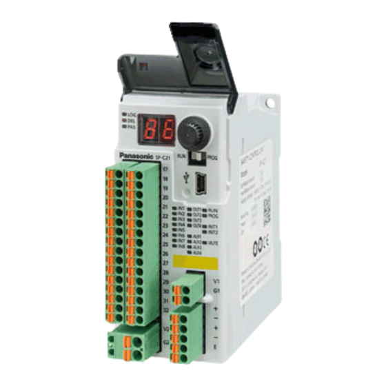
PART NAMES
Logic selection indicator (Orange)
Delay selection indicator (Orange)
Password selection indicator (Orange)
Terminal block for
I/O 2
Terminal block for
I/O 1
Indicator A
Terminal block
for external
power supply
DIN rail stopper
DIP switch for RS-485
4
MOUNTING
● When installing this device, make sure that it is correctly oriented: The device
must be installed vertically with its indicators and terminal blocks facing the opera-
tor side in order to ensure heat dissipation.
Installed in vertically
reversed orientation
● In addition, make sure that the device's upper, low-
er, left, and right surfaces are spaced by a 50mm or
more from surrounding objects such as other devic-
es and wiring ducts.
● Do not install the unit above devices which generate heat such as heaters, trans-
formers or large scale resistors.
● In order to eliminate any effects from noise emission, power wires and electro-
magnetic devices should be kept a 100mm or more away from the surfaces of the
device. When installing the unit behind the doors of the control board, be espe-
cially careful to secure clearances as above.
SF-C21
MAINTENANCE."
9
1 pc. each language
[Indicator A]
Input 1 indicator (Orange)
Input 2 indicator (Orange)
Input 3 indicator (Orange)
7-segment indicator (Red)
Input 4 indicator (Orange)
Rotary switch
Input 5 indicator (Orange)
Input 6 indicator (Orange)
Mode selection switch
Input 7 indicator (Orange)
Input 8 indicator (Orange)
USB connector (miniB)
[Indicator B]
Indicator B
Output 1 indicator (Green)
Output 2 indicator (Green)
Indicator C
Output 3 indicator (Green)
Output 4 indicator (Green)
Auxiliary output 1 indicator (Orange)
Terminal block for
Auxiliary output 2 indicator (Orange)
internal power supply
Auxiliary output 3 indicator (Orange)
Auxiliary output 4 indicator (Orange)
Terminal block for
[Indicator C]
RS-485
Operation indicator (Green)
Setting indicator (Orange)
Interlock 1 indicator (Yellow)
Interlock 2 indicator (Yellow)
Muting indicator (Orange)
Horizontally installed
Sideways installed
50mm
or more
100mm or more
Other
devices
1 pc.
50mm
or more
50mm
or more
50mm
or more
Advertisement

Related Manuals for Panasonic SF-C21


Summary of Contents for Panasonic SF-C21
- Page 1 • Clean this device with a clean cloth. Do not use any volatile chemicals. Thank you very much for purchasing Panasonic products. Read this Instruction Man- ual carefully and thoroughly for the correct and optimum use of this product. Kindly ♦...
- Page 2 ● Installation to and removal from a DIN rail <Reference> Compatible DIN rail models (based on JIS C 2812) The power supply unit must satisfy the conditions given below. - TH35-7.5Al or TH35-7.5Fe 1) Power supply unit authorized in the region where this device is to be used. 2) Power supply unit SELV (safety extra low voltage) / PELV (protected extra low Installing voltage) conforming to EMC Directive and Low-voltage Directive (In case CE...
- Page 3 ● Example: preset logic No.1 manual reset <Reference> ● In the event of a failure or error, refer to “SF-C21 Instruction Manual” and pro- vide the details to an authorized engineer. ● If the problem cannot be resolved internally, contact our office.
- Page 4 AUX2: Negative logic output of OUT3 and/or OUT4 (ON when OUT3 and/or OUT4 are OFF) (Factory defaults) AUX3: Reset trigger output (ON when reset condition is met) Manufacturer’s Name: Panasonic Industrial Devices SUNX Co., Ltd. AUX4: Lockout output (OFF when lockout) Manufacturer’s Address: 2431-1, Ushiyama-cho, Kasugai, Aichi 486-0901, Japan •...