
Related Manuals for Bosch rexroth SB11


Summary of Contents for Bosch rexroth SB11
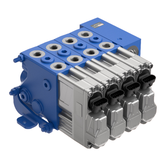
- Page 1 Assembly instructions 10-R Load-sensing control block in sandwich plate design SB11 RE 66177-10-R/2021-11-16, EN...
- Page 2 © Bosch Rexroth AG 2021. All rights reserved, also regarding any disposal, exploitation, reproduction, editing, distribution, as well as in the event of applications for industrial property rights. The data specified within only serves to describe the product. No statements concerning a certain condition or suitability for a certain application can be derived from our information.
-
Page 3: Table Of Contents
............ 13 5.2.3 Disassembly, directional valve section ........14 5.2.4 Disassembly, connecting plate ............... 14 Repairing the flange surface ������������������������������������������������������������������� 15 Sealing elements for control block segments ..........15 Repairing the shuttle valve ................. 16 RE 66177-10-R/2021-11-16, Bosch Rexroth AG... -
Page 4: About This Documentation
Load-sensing control block SB11 | About this documentation 1 About this documentation 1�1 Validity of the documentation This documentation applies to load-sensing control blocks SB11 of Bosch Rexroth including the following control block segments: • Connecting plate, end plate • Control valves SB11-EHS4 •... -
Page 5: Representation Of Information
Table 4: Abbreviations Abbreviation Meaning Connecting plate Electrohydraulic hitch control Electro-hydraulic actuating unit End valve (with LS signaling direction from left to right) End plate Standard valve (with LS signaling direction from left to right) RE 66177-10-R/2021-11-16, Bosch Rexroth AG... -
Page 6: Safety Instructions
• Reworking sealing surfaces is not permissible. Bench vise • Use protective jaws with hard rubber. Sealing and flange surfaces may not be damaged. • Oil-soaked cleaning cloth Required tools • Whetstone • Mechanical tools • Torque wrench Bosch Rexroth AG, RE 66177-10-R/2021-11-16... -
Page 7: About These Products
The appearance of the individual control block segments may vary. 4�1 Overview of control block segments Plates ▲ End plate (EP) ▲ Connecting plate (AP) Directional valves ▲ End valve (EVR) ▲ Standard valve (SVR) ▲ Hitch control valve EHR11-EHS4 RE 66177-10-R/2021-11-16, Bosch Rexroth AG... -
Page 8: Tie Rod Bores And Threads
Thread EP / EVR 4�3 Tie rod and nut Tie rods used by Bosch Rexroth are symmetrical, differentiation of the thread ends is not necessary. ▶ Use tie rods M8 × length, property class 10.9. ▶ The required tie rod length depends on the number and combination of the control block segments. -
Page 9: Configuring The Control Block
In case of horizontal assembly, the height difference of the individual block segments should be compensated with a suitable underlayer from the fifth control block segment in order to ensure safe orientation of the control block segments to each other. ▲ Compensating height differences RE 66177-10-R/2021-11-16, Bosch Rexroth AG... -
Page 10: Assembly Description
Prepare the flange surface O-ring side of the block segments as follows: 1� Block segments with shuttle valve: Assemble the shuttle valve according to chapter 6.2 "Repairing the shuttle valve". 2� Assemble the sealing elements according to chapter 6.1 "Sealing elements for control block segments". Bosch Rexroth AG, RE 66177-10-R/2021-11-16... -
Page 11: Assembly, Connecting Plate
5�1�3 Assembly, directional valve section ▶ Orientate the control block segment with the flange surface of the opposite O-ring side to the connecting plate and slide it via the tie rod screws to the stop at the connecting plate RE 66177-10-R/2021-11-16, Bosch Rexroth AG... -
Page 12: Assembly, Directional Valve Section And
O-ring side to the already mounted control block segment and slide on via the tie rod screws to the stop. 2� Screw the nuts onto the tie rods without using any washers or locking washers. Bosch Rexroth AG, RE 66177-10-R/2021-11-16... -
Page 13: Control Block Disassembly
/ end valve 1� Loosen the nuts by turning them counterclockwise and remove them from the tie rods … . 2� Remove the end plate / end valve via the tie rods … without jamming. RE 66177-10-R/2021-11-16, Bosch Rexroth AG... -
Page 14: Disassembly, Directional Valve Section , And
▶ Remove the control block segments one after another via the tie rods … . 5�2�4 Disassembly, connecting plate ▶ Loosen the three tie rods … by turning them counterclockwise and unscrew them from the connecting plate Bosch Rexroth AG, RE 66177-10-R/2021-11-16... -
Page 15: Repairing The Flange Surface
2� Insert new O-rings into the ports P, R, Y, Rx and X in the flange surface. sealing elements ▲ Flange surface Control block segments with a recess for an O-ring for X (without continuous bore through the valve housing) must also be equipped with O-rings. RE 66177-10-R/2021-11-16, Bosch Rexroth AG... -
Page 16: Repairing The Shuttle Valve
4� Check the distance dimension 0.5 mm from the flange surface of the control block segment to the upper edge of the inserted shuttle valve. 5� Insert a new O-ring into port Y. NOTICE! The shuttle valve must remain freely movable within the O-ring Bosch Rexroth AG, RE 66177-10-R/2021-11-16... - Page 17 | Load-sensing control block SB11 17/18 RE 66177-10-R/2021-11-16, Bosch Rexroth AG...
- Page 18 Bosch Rexroth AG Robert-Bosch-Straße 2 71701 Schwieberdingen Germany Service phone +49 (0) 9352 40 50 60 Aftermarket@boschrexroth.de www.boschrexroth.com/eshop Your local contact person can be found at: https://addresses.boschrexroth.com Subject to change RE 66177-10-R/2021-11-16...